Havener Enterprises EVEN CUT 22DP User manual


2
IMPORTANT MESSAGE
This machine comes with an Owner’s Manual and List. The useful life and good service
you receive from this machine depends to a large extent on how well you read and
understand this manual . Treat your machine properly, lubricate and adjust it as instructed,
and it will give you many years of reliable service.
Your safe use of this product is one of our prime objectives. Many safety features are built
in,but we also rely on your good sense and care to achieve accident-free operation. For
best protection, study the manual thoroughly. Learn the proper operation of all controls.
Observe all safety precautions. Follow all instructions and warnings completely. Do not
remove or defeat any safety features.
See a Havener Enterprises, Inc. dealer for any service or parts needed. Havener
Enterprises, Inc. service ensures that you continue to receive the best results possible
from Havener Enterprises, Inc. products. You can trust Havener Enterprises, Inc.
replacement parts because they are manufactured with the same high precision and
quality as the original parts.
Havener Enterprises, Inc. designs and builds its equipment to serve many years in a safe
and productive manner. For longest life, use this machine only as directed in the manual,
keep it in good repair and follow safety warnings and instructions.

3
IMPORTANT INSTRUCTIONS:
Read the owner’s manual and make it readily available for future reference.
Be familiar with the operation of the mower. Extreme emphasis should be placed on
operator safety and the mower's safety features.
Know the correct mower and engine service and maintenance requirements, and be able
to perform or have performed the service and recommended lubrication as required.
GENERAL
Before servicing, check the mower for such items as belt tension and cutting height
adjustment, to be sure mower functions properly. Check attachment of the rear guard and
inspect to make sure the chute guard is secure.
HANDLEBARS
This mower is shipped with the handlebars detached. Handlebars must be bolted into
position before use. All controls must be properly mounted to the handlebars before
starting.
RAPAIRS OR SERVICE
IMPORTANT: If service or parts are required, be prepared to supply the service person
with the model and serial number of the mower and engine. Include a complete
description of the problem encountered.
TRAINING
Read the operating and service instruction manual carefully and completely. Be familiar
with all safety controls and the proper use of the equipment.
NEVER
let a child operate a power mower.
Keep the area of operation clear of all persons, especially small children and pets.
PREPARATION
1. Never operate your power mower unless ALL GUARDS are securely attached Do not
remove rear guard!
2. Thoroughly inspect area where the mower will be used. Remove all stones, sticks,
bones and other foreign objects.
3. Wear long pants and substantial shoes when operating the mower. Do not operate
mower-wearing sandals, tennis shoes, sneakers, shorts or loose-fitting clothing that
could be caught in moving parts.

4
4. Check gas level before starting engine. Do not fill gas tank indoors, when the engine is
running, or while the engine is still hot, Wipe off any spilled gasoline before starting
engine.
5. Mow only in daylight.
6. Never operate a mower in wet grass. Always be sure of your footing, keep a firm hold
on the handle, and walk.NEVER RUN!
7. NEVER operate a mower without proper eye and hearing protection, i.e.: safety
glasses face shield or goggles.
STARTING & STOPPING
1. Fill the engine crankcase with oil. Refer to the engine instruction manual supplied with
this mower.
2. Fill the gas tank. Refer to engine manual.
3. Set throttle control to proper position to START
4. Hold lever against the handlebar and pull recoil starter cord See figure 3
NOTE: Return cord slowly-DO NOT LET HANDLE SNAP!
REMEMBER:
The lever control must be held against handlebar to operate the mower. See Figure 1
When the lever is release, the engine and blade will stop.
GOING FORWARD:
Slowly press the control lever down and the mower will start to move forward (Note: Only
the 24B6.75SP can do this).
TO STOP
1. Release all lever controls, engine, and blade will stop. See Figure 2
2. IMPORTANT: Release the lever control this will STOP the blade and engine. If this
feature fails to function, DO NOT OPERATE MOWER. Disconnect the spark plug wire
and see your Even Cut dealer.
1 2 3

5
REMEMBER: The safety features on this mower are for your protection. Do not tamper
with or remove these components.
OPERATION
1. Do not change the engine governor setting or over speed the
engine.
2. Do not put hands or feet near or under rotating parts. Stay clear of
discharge area while the engine is running (Figure.5).
3. Stop the mower when crossing gravel drives, walks, roads, or any
other area where thrown objects may be a hazard.
4. After striking a foreign object, or if the mower vibrates abnormally,
stop the engine, disconnect, and secure the spark plug wire,
Inspect the mower for any damage before restarting.
5. Before cleaning, repairing, or inspecting, make certain the blade and all other moving
parts have come to a complete stop. Disconnect the spark plug and secure the wire
away plug to prevent accidental starting.
6. Do not run the engine indoors.
7. Mow across the face of slope, never up and down. Exercise extreme caution when
changing directions on slopes. Do not mow excessively steep slopes.
MAINTENANCE & STORAGE
1. In order for your safety controls to function at the peak of efficiency, they must be
inspected and adjusted regularly. Initial inspection shall take place after the first two (2)
hours. Belt tension is a very critical part of your safety inspection, and should be
checked frequently.
2. Keep all nuts, bolts and screws tight to assure safe mower operation.
3. Never store equipment with gas in the tank or in a building near a spark or flame.
Allow the engine to cool before storing in any enclosure.
4. To reduce fire hazard, keep mower free of grass, leaves or excessive grease.
5. Have your mower service and inspected every year by your authorized Even Cut
dealer, and if you perform repairs yourself, use only Even Cut replacement parts.
IMPORTANT:
If service or parts are required, be prepared to supply the service person with the model
and serial number of the mower and engine Include a complete description of the problem
encountered.
ENGINE GENERAL
Follow the engine manual supplied with this mower for proper engine maintenance and
service. The engine on your Even Cut mower is an item for which the manufacturer
maintains a national service organization. FOR ENGINE PARTS AND REPAIR
INSTRUCTIONS, CONTACT THE ENGINE MANUFACTURER'S DEALER. Your engine is
Figure 5

6
designed for long lasting service when given proper care. For the proper care instructions,
READ YOUR ENGINE MANUAL!
SPECIAL SERVICE INSTRUCTIONS
Check oil level before every mowing.
Change Oil every eight to ten hours of operation. Use high quality SAE 30 oil.
Use unleaded gasoline.
Keep your engine clean. Dirt and grass accumulation can result in serious damage to the
precision parts of your engine.
ENGINE SERVICE
Refer to engine owner's manual.
CAUTION: BE SURE TO HANDLE FUEL OUTDOORS, AWAY FROM SPARK OR
FLAME.
LUBRICATION
To lubricate your Even Cut Mower, apply bearing grease through the fitting on the hub
housing. You may use an air pressure or hand-held grease gun. To lubricate the wheels
on your Even Cut Mower high quality grease may be packed inside the wheel hubs.
CUTTING HEIGHT ADJUSTMENT
Your Even Cut is adjustable to a accommodated your cutting height requirements by lower
and raising the front and rear wheels.
BLADE SHARPENING-CAUTION
CAUTION: WHEN ADJUSTING, REPLACING OR MOVING THE MOWER BLADE, THE
SPARK PLUG WIRE MUST BE DISCONNECTED TO AVOID ACCIDENTAL STARTING.
CLEANING YOUR EVEN CUT MOWER
Clean your Even Cut after each use. Let the engine cool, and then wipe the grass and
debris from mower and engine. Check mower pan for grass and dirt build-up. Disconnect
the spark plug and tip mower on its side (muffler side up) to clean underneath deck.
Check the blade and mounting hardware at frequent intervals for wear and tightness.
Replace worn parts with Even Cut original equipment parts for safety

7
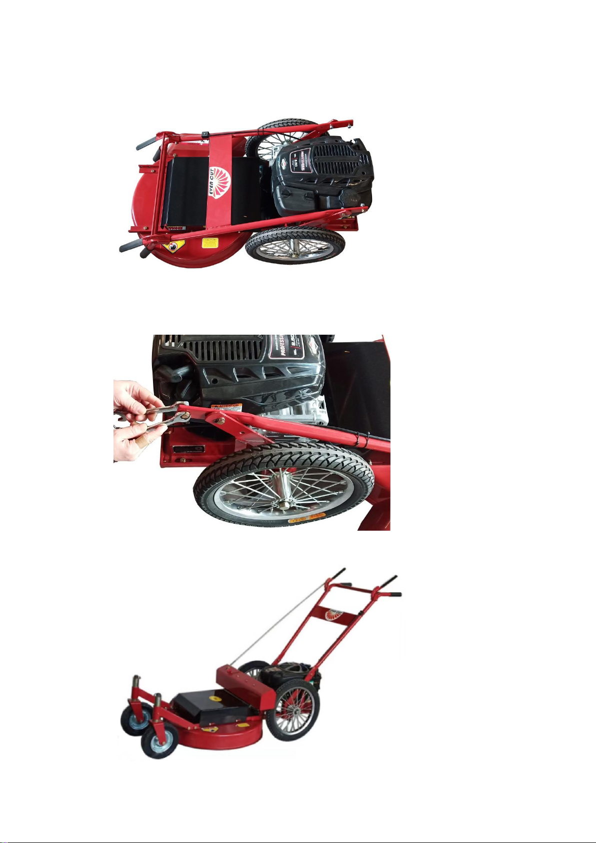
Unpacking
Instructions
8
1.Take out the mower from the carton.
2.Take off the handle bar by using two 13mm wrenches.
3.Assemble the handle bar and tighten the four bolts as shown below:
9
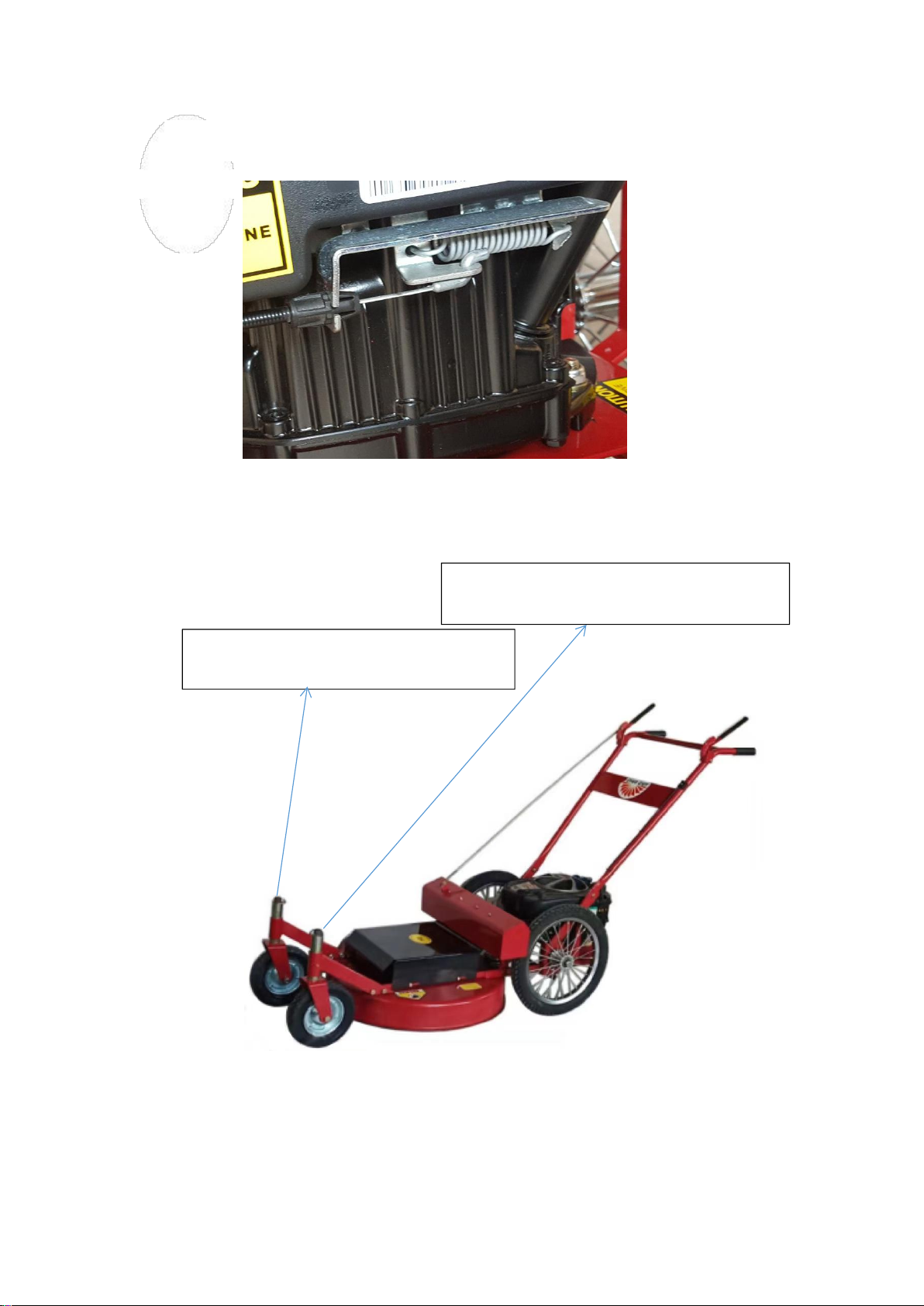
4.Hook up the throttle cable as shown below:
5. Install the swivel front wheel for BP, SP only
Install the front wheel assembly: Take off the nut from the swivel wheel and then install the
front wheel assembly on the deck frame, tighten it with the wrench.
Right front swivel wheel assembly
Left front swivel wheel assembly

10
6.Install the grass chute and tighten the two blots as shown below marked in yellow.
7.Install the walking rod as shown below.
Please note only the 24SP mower has this part.
Handle height
40±1''

11
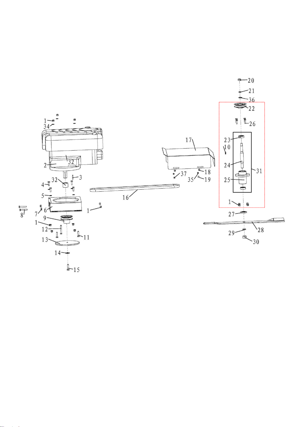
22DP Assembly
43

12
Item No.
Part Number
Description
Qty
1
400-001
Grip
2
2
400-034
Handle Grip
2
3
200-327
Hexagon Bolt M6-1x45 GB5782
2
4
400-003
Bail
1
5
400-035
Plow Handle
1
6
200-021
Plain Washer 8 GB95
8
7
200-009
Nylon Nut M6 GB889
8
8
200-013
Nylon Nut M5 GB889
1
9
200-174
Nut Thin M14 GB6172.1
2
10
400-029
Safety Cable
1
11
200-173
Bolt M5-0.8x40 GB818
1
12
200-119
Hexagon Bolt M8-1.25x25 GB5783
4
13
200-030
Nylon Nut M8 GB889
10
14
400-025A
Back Wheel Axle-Hex Head
2
15
400-026P
Back Wheel-Pneumatic 16x2.125
2
16
200-036
Hexagon Bolt M6-1x20 GB5783
4
17
422A-001
Bracket
1
18
600-205-0014
Nylon Nut M14 DIN985
2
19
424A-039
Spacer for Wheel
2
20
400-008
Front Wheel Axle
2
21
400-009
Front Wheel
2
22
200-318
Bearing 6202-2RS
4
23
600-002-0840
Hexagon Bolt M8-1.25x40 GB5783
2
24
400-014
Engine Bolt
1
25
400-044
Washer
1
26
422A-002
Straight Blade 22"
1
27
422A-003
Blade Saddle 22.2mm
1
422A-003A
Blade Saddle 25mm
1
28
422A-006
Chute
1
29
200-178
Hexagon Bolt M8-1.25x16 GB5783
3
30
200-106
Woodruff key 4x6.5x16 GB1099
1
200-350
Flat key 6.35x6x30 GB1096
1
31
424A-073
Engine Assembly
1
32
400-011
Rear Deflector
1
33
422A-004
Flange Deck
1
34
422A-005
Mover Frame For 22"(A)
1
35
200-177
Hexagon Bolt M6-1x35 GB5783
4
36
200-107
Hexagon Nut M12 GB6170
2
37
200-220
Hexagon Bolt M8-1.25x70 GB5782
1
38
200-007
Nylon Nut M12 GB889
2
22DP Assembly

13
39
400-020a
Spacer, Bearing
4
40
600-604-0010
Lock Washer 3/8
1
41
200-301
Plain Washer 6 GB95
11
42
200-053
Lock washer 6 GB93
3
46
200-120
Hexagon Bolt M6-1x16 GB5783
3
47
200-138
Plain washer 5 GB95
1
48
600-205-0006
Nut M6 DIN985
2
optional
43
400-026
Solid tire assembly
2
44
424A-039A
Spacer for Wheel
2
45
424A-068
Standard 3/4″ball bearing
4
14
22BP Gearing Assembly
33

15
22BP Gearing Assembly
Item No.
Part Number
Description
Qty
1
200-030
Nylon Nut M8 GB889
13
2
424A-073
Engine Assembly
1
3
100-139
Flat key6.35x6x38
1
4
200-119
Hexagon Bolt M8-1.25x25 GB5783
4
5
336-239
Plain Washer 3*8.5 id *20 od
4
6
400-030
Engine Mount (For 2018 or earlier)
1
400-030A
Engine Mount(( For 2021upgrade design)
1
7
600-202-0008
Nut Flange M8 QC864
2
8
200-179
Hexagon Bolt M8-1.25x50 GB5783
2
9
400-060
Engine Pulley 25mm
1
10
200-125
Key 5x6.5x16 GB1099-97
1
11
200-049
Hexagon Bolt M8-1.25x35 GB5783
2
12
200-220
Hexagon Bolt M8-1.25x70 GB5782
1
13
400-021
Fly Wheel
1
14
600-902-0010
Butterfly Washer 10 DIN6796
1
15
400-014
Engine Bolt
1
16
400-033
High wheel deck Belt LA55-AGX
1
17
422B-005
Master Link For 22"(B)
1
18
200-042
Plain Washer 6 GB95
4
19
200-036
Hexagon Bolt M6-1x20 GB5783
2
20
200-124
Hexagon Nut M12x1.5 GB6171
1
21
200-078
Lock Washer 12 GB93
1
22
400-032A
Pulley
1
23
200-110
Bearing 6203-2RS
2
24
422B-002A
Hub Shaft
1
25
400-015a
Bearing Housing
1
26
200-025
Hexagon Bolt M8-1.25x30 GB5783
4
27
400-019
Blade Spacer
1
28
422B-001
Blade 22"
1
29
200-096
Lock Washer 16 GB93
1
30
200-017
Hexagon Nut M16x1.5 GB6171
1
31
422B-007A
Cutter Housing Assembly
1
32
424A-071
Straight Pivot
1
33
400-045
Spindle assembly
1
34
600-301-0008
Plain Washer 8 GB95
3
35
600-305-0006
Lock Washer 6 GB93
4
36
600-301-0012
Plain Washer 12 GB95
1
37
200-313
Hexagon Bolt M6-1x25 GB5783
2

16
22BP Frame Assembly

17
Item No.
Part Number
Description
Qty
1
400-001
Grip
2
2
400-034
Handle Grip
2
3
200-327
Hexagon Bolt M6-1x45 GB5782
2
4
400-003
Bail
1
5
400-035
Plow Handle
1
6
200-021
Plain Washer 8 GB95
8
7
200-009
Nylon Nut M6 GB889
4
8
200-013
Nylon Nut M5 GB889
1
9
600-205-0014
Nylon Nut M14 DIN985
2
10
400-005
Safety Cable
1
11
200-173
Bolt M5-0.8x40 GB818
1
12
200-119
Hexagon Bolt M8-1.25x25 GB5783
8
13
200-030
Nylon Nut M8 GB889
10
14
200-036
Hexagon bolt M6-1x20 GB5783
4
15
422B-006
Rear Deflector
1
16
400-025A
Back Wheel Axle-Hex Head
2
17
200-318
Bearing 6202-2RS
4
18
400-026P
Back Wheel-Pneumatic 16x2.125
2
19
200-174
Nut thin M14 GB6172.1
2
20
422B-003
Mover Frame For 22"(B)
1
21
400-010
Chute Ext
1
22
200-178
Hexagon Bolt M8-1.25x16 GB5783
2
23
200-091
Hexagon Bolt M8-1.25x20 GB5783
4
24
422B-004
Deck Weldment
1
25
200-006
Nylon Nut M10 GB889
1
26
400-020a
Back wheel washer
4
27
424A-039
Spacer for Wheel
2
28
WM2836-052
Idle Pulley
1
29
200-068
Hexagon Bolt M10-1.5x55 GB5782
1
30
200-331
Plain washer 6 GB96
4
31
200-042
Plain Washer 6 GB95
12
32
200-147
Plain Washer 10 GB96
2
33
400-042
Spacer
1
37
200-138
Plain washer 5GB95
1
38
600-205-0006
Nut M6 DIN985
2
optional
34
424A-068
Standard 3/4″ball bearing
4
35
424A-039A
Spacer for Wheel-Pneumatic
2
36
400-026
Solid tire assembly
2
22BP Frame Assembly

18
22BP,24SP Front Wheel Assembly
Front wheel assembly
for 2020 or earlier
discontinued
Front wheel assembly
for 2021 upgrade
design
20
21
Discontinued
See#23
2024
upgrade
design

19
22BP, 24SP Front Wheel Assembly
Item No.
Part Number
Description
Qty
1
400-008
Front wheel axle
2
2
400-009
Front wheel
2
3
200-107
Hexagon Nut M12 GB6170
2
4
600-205-0012
Nylon nut M12 DIN985
2
5
400-018
Front end
1
6
200-109
Pin 10x20 GB882
4
7
200-006
Nylon Nut M10GB889
4
8
400-017
Space
2
9
400-016
Height adjustment
4
10
200-103
Hexagon Bolt M10-1.5x30 GB5783
4
11
200-069
Hair Pin Cotter
2
12
200-071
Plain Washer 12 GB95
4
410-005
Front wheel spacer(for 2022 upgrade design)
4
13
410-003
Castor Yoke
2
14
200-026
Grease Fitting M6 GB1152
2
15
410-001
Spacer Sleeve
2
16
15023
Lynch Pin Tire
2
17
15005
Bronze Pivot Bushing
4
18
410-002-R
Right front yoke weldment
1
410-002-L
Left front yoke weldment
1
19
200-019
Hexagon Bolt M10-1.5x40 GB5782
4
20
410-004
Front Wheel Assembly
1
21
410-000
Swivel Wheel Assembly
2
22
410-006
Adjustable washer
2
23
410-007
Spacer Sleeve I
8

20
24SP Gearing Assembly
Spindle assembly new
design
35
Different parts compared with
the upgrade spindle
41
Upgraded parts
This manual suits for next models
2
Table of contents
Other Havener Enterprises Lawn Mower manuals

Havener Enterprises
Havener Enterprises BRADLEY MOWERS 36 User manual

Havener Enterprises
Havener Enterprises BRADLEY MOWERS 36 User manual

Havener Enterprises
Havener Enterprises BRADLEY MOWERS 48 User manual

Havener Enterprises
Havener Enterprises BRADLEY MOWERS 36 User manual

Havener Enterprises
Havener Enterprises BRADLEY MOWERS 32 User manual

Havener Enterprises
Havener Enterprises BRADLEY MOWERS 61SC User manual


