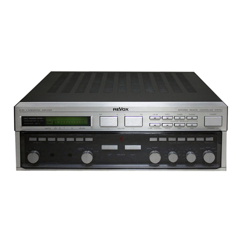
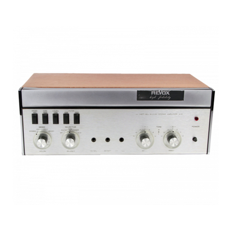
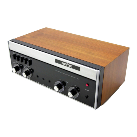
Revox B750 User manual


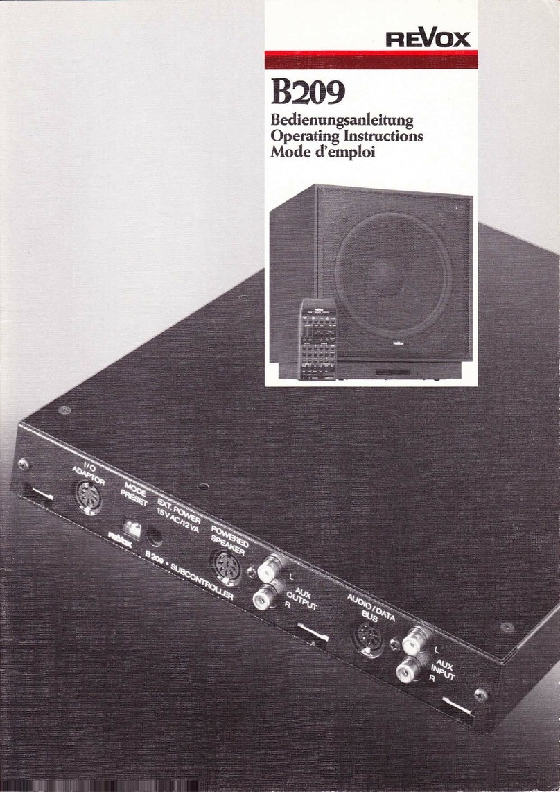
Kompaktverstärker B750
Bedienungsanleitung
Compact amplifier B750
Operating Instructions
Amplificateur compact B750
Mode d'emploi

Wir danken Ihnen für das Vertrauen, das Sie uns
mit der Wahl eines Kompaktverstärkers 13750
entgegengebracht haben.
The confidence that you have shown in REVOX
products by choosing a 13750 Compact Stereo
Amplifier is very much appreciated.
Nous vous remercions de la confiance que vous
nous avez tämoignäe en portant votre choix sur
I
'
amplificateur Compact 13750.
Wichtige Hinweise
Schützen Sie Ihr Gerät vor Hitze und Feuchtig-
keit. Lüftungsschlitze dürfen nicht verdeckt wer-
den; achten Sie auf freie Luftzirkulation.
Vor dem Öffnen des Gerätes ist unbe-
dingt zuerst der Netzstecker zu ziehen.
I
n die-
sem Zusammenhang machen wir Sie auf die
Garantiebestimmungen aufmerksam.
Gerät darf nur an Wechselspan-
werden (50 oder
Das
nungsnetze angeschlossen
60 Hz).
I
mportant notes
Protect your valuable equipment from excessive
heat and humidity. Do not block the free cir-
culation of air. Do not cover any of the air
vents.
Disconnect mains plug before opening
the equipment I
n this connection we draw your
attention to the general conditions of warranty.
Be sure to tonnett the unit to 50 or
60 Hz AC mains supplies only.
Avis importants
Protägez votre appareil de la chaleur et de
I'
humiditä. Les fentes d'aäration ne doivent en
aucun cas etre recouvertes, mais avoir suffisam-
ment d'espace libre pour une bonne circulation
d'air.
Avant toute intervention ä l7nterieur de
l
appareil, il est imperatif de retirer la fiche sec-
teur.
Nous vous rappelons ä ce sujet les clauses
de garantie.
L'appareil ne peut etre alimentä qu'en
courant alternatif (50 ou 60 Hz).
Garantie
Allen Geräten, die in
Belgien, BR-Deutschland,
Frankreich
und der
Schweiz
verkauft werden,
liegt
eine spezielle Garantie-Anforderungskarte
bei.
Entweder ist diese beigepackt, oder sie be-
findet sich auf der Aussenseite der Verpackung
i
n einer Plastiktasche. Sollte diese Karte fehlen,
wenden Sie sich bitte an Ihr REVOX-Fachge-
schäft
oder an die REVOX-Vertretung Ihres
Landes.
Bitte
füllen
Sie
die
Garantie-Anfor-
derungskarte aus, und senden Sie diese an die
REVOX-Vertretung des Verkaufslandes. Unser
zentraler Kundendienst wird Ihnen darauf eine
persönliche Garantie-Checkkarte zustellen.
Beachten Sie bitte, dass die Garantie nur
i
m Lande des Kaufes gültig ist. Ausserdem
machen wir Sie darauf aufmerksam, dass wir
von jeglicher Verpflichtung befreit sind, sofern
am Gerät unsachgemässe Eingriffe oder nicht-
fachmännische
Reparaturen
vorgenommen
werden.
Warranty conditions
Your dealer and his national distributor guaran-
tee the faultless operation of this REVOX com-
ponent. Please ask your dealer for a correspond-
i
ng warranty certificate.
The warranty is not valid outside the
country of purchase.
For equipment purchased in
Selgium,
the
Federal Republic of Germany, France
and
Switzerland,
there exists a special warranty ap
plication card, which is either contained in a
plastic envelope attached to the outside of the
packing carton or it is enclosed with the equip-
ment. If this card is missing, please request it
from your dealer.
The completed warranty application is
to be returned to the national distributor who
will then send you your warranty card.
Garantie
Pour tous les appareils vendus en
Selgique,
RFA, France
et
Suisse, vous
trouverez, soit ä
I
'i
ntärieur de I'emballage soit dans une pochette
en plastique fixäe ä I'extärieur, un formulaire de
demande de garantie. Si ce dernier devait uran-
quer, votre fournisseur ou I'agent officiel du
pays d'achat se fera un plaisir de vous le pro-
curer.
Apräs I'avoir rempli, envoyez ce for-
mulaire ä I'agence officielle du pays d'achat;
vous recevrez en retour votre carte de garantie
dans les plus brefs dälais.
La garantie n'est valable que dans le
pays oü ä lieu I'achat. Nous vous rendons at-
tentif au fait que toute intervention non auto
risäe dans I'appareil nous libäre de toute obliga-
tion.
Verpackung
Bewahren Sie die Original-Verpackung auf. Für
einen möglichen Transport ist diese Spezialver-
packung der beste Schutz für Ihr wertvolles
Gerät.
Packing
Do not destroy the original packing. If you ever
have to transport your equipment, this special
packing will provide best possible protection.
Emballage
Conservez I'emballage original. Dans le cas d'un
transport ultärieur, il est la meilleure protection
de votre appareil.
2

Über den Gebrauch dieser Anleitung
Damit Sie nicht gleich die ganze Anleitung zu
l
esen brauchen, ist der Inhalt in drei themati-
sche Kapitel eingeteilt.
Primär-Information
Lesen Sie bitte diese Spalte und die Indexliste
bis
Seite 9. Dann wissen Sie bereits über die
Bedienungselemente und die Anschlüsse Be-
scheid; den "Insidern" wird diese Information
als
An!eitung genügen. Konsultieren Sie immer
zuerst diese Liste, falls Ihnen ein Bedienungs-
element noch nicht oder nicht mehr vertraut ist.
'
Schritt für Schritt' -Anleitung
Dieses Kapitel benötigt etwas mehr Zeit für die
praktische Erprobung. Die Indexzahlen in den
Kreisen beziehen sich immer auf die Illustra-
tionen auf den ausklappbaren Seiten.
Technik und Zusammenschalten mehre-
rer Geräte
Am Schluss der Anleitung finden Sie Technische
Daten,
Verbindungsdarstellungen zum Zusam-
menschalten
kompletter HiFi-Anlagen sowie
Funktionsdiagramme für technisch Interessierte.
...
und noch einige Tips zu Beginn:
-
Prüfen Sie die Stellung des Spannungs-
wählers vor Anschluss des Gerätes ans Netz
-
Einrastende Tasten durch nochmaliges
Drücken lösen.
-
Beim Anschluss von DIN-Steckern auf
die Führungsnocken achten.
-
Cinch-Stecker ganz einstecken (sonst
"brummt" es).
-
Beim Anschluss von Cinch-Steckern auf
die Kanalzuordnung achten:
l i
nks
= L= CH I = Al/W1
rechts = R = CH I I = A2/W2
Falten Sie die ausklappbaren Seiten nach aus-
sen, es kann losgehen!
How to use this manual
To safe you from having to read the complete
i
nstructions before operating the equipment for
the fist time, we have written three separate
chapters.
Basic information
Please read this page and the index list up to
page 9. After having done this, you will already
be familiar with the operating controls and the
i
nput and output connections. For "HiFi Ex-
peris" this may already be sufficient for being
able to operate the equipment. Always consult
this [ist first if you are not yet (or no longer)
fully familiar with the function of a particular
operating control.
Step by step instructions
This chapter describes each operation in detail
and some time will be required in familiarizing
oneself with each function. The encircled index
numbers refer to the illustrations an the fold-
out pages.
Technical information
and complete
system set-ups
At the end of this manual, the technically in-
terested user will find a tabulation of the equip-
ment's performance characteristics, suggested
music system set-ups and block diagrams.
...
and now a few Pointers before starting:
-
Check the setting of the voltage selector
before connecting the equipment to the AC
Power line.
-
Locking buttons are to be released by
pressing them again.
-
When connecting DIN plugs, ensure
proper mating by observihg their keyway.
-
Phone plugs must be pushed home fully,
otherwise you might get "hum".
-
When using phono plugs, observe correct
channel assignment:
l
eft
=L=CH I
=A1/W1
right
= R = CH I I
= A2/W2
Turn the fold-out pages outward and you are all
set to give it a first try!
Comment utiliser ce mode d'emploi
Afin
de ne pas devoir lire tout le mode d'emploi
pour chaque operation, celui-ci est divise en
trois chapitres.
Information primaire
Pour vous familiariser avec les diffärents organes
de commande et prises de raccordements, nous
vous conseillons de lire cette page et celles du
räpertoire jusqu'ä la Page 9. Ce repertoire est ä
consulter en premier lieu, chaque fois qu'il aura
un doute sur la fonction d'un ou des organes de
commande.
Description progressive
Ce chapitre näcessite un peu plus de temps pour
I
'
etude pratique des organes de commande. Aux
chiffres
entouräs d'un cercle, correspondent
toujours les illustrations des feuillets replies.
Technique et raccordement ä d autres
appareils
La f in de ce mode d'emploi comporte les carac-
täristiques techniques, les descriptions pour le
raccordement ä une installation Hi-Fi complete,
ainsi
que des repräsentations graphiques des
fonctions pour ceux que la technique intäresse.
...
et encore quelques indications avant de com-
mencer
-
Avant de raccorder I'appareil au secteur,
verifiez la Position du selecteur de tension.
-
Libärez les touches enfoncees par une
nouvelle pression.
-
Lors de raccordement par fiche DIN
respectez I'ergot de guidage.
-
Enfoncez
completement les fiches
Cinch.
-
Attention ä fordre des canaux des fiches
de raccordement Cinch:
gauche=L=CH1 =A1/W1
droit
= R = CH 11 = A2/W1
Ouvrez les feuillets replies et commenpons!
3

4


I
ndexliste der Bedienungselemente und
Anschlüsse
I
n der nachfolgenden Auflistung sind alle Be-
dienungselemente und Anschlüsse erwähnt und
kurz erläutert.
(1)
Netzschalter POWER, ON/OFF
(
Ein/Aus)
Beim Einschalten ist der Verstärker erst nach
einer
Verzögerungszeit von ca. 4 ... 5 sec be-
triebsbereit.
(
Bevor Sie das Gerät am Netz anschliessen, ist
der
Spannungswähler zu kontrollieren, bitte
I
NDEX 46 beachten).
Betriebsanzeige POWER ON
Leuchtet bei eingeschaltetem Gerät.
(3)
Lautstärkeabsenkung LEVEL -20 dB
Bei gedrückter Taste wird die Lautstärke linear
um 20d13 abgesenkt. Diese Absenkung ge-
schieht unabhängig von der Stellung des Laut-
stärkereglers VOLUME.
Lautstärkeregler VOLUME
Lineare
Lautstärkeregelung. Für gehörrichtige
Korrektur
bei
kleinen
Lautstärken
Schalter
LOUDNESS 12 benutzen.
(5)
BALANCE-Regler
Zur Balancekorrektur bei unsymmetrischer Auf-
stellung der Lautsprecher.
(6)
Betriebsartenschalter MODE
SELECTOR
Die Stellung des Betriebsartenschalters MODE
SELECTOR bestimmt über die Art der Wieder-
gabe an den Vorverstärker-, Lautsprecher- und
Kopfhörerausgängen.
Schaltstellungen:
STEREO
Bevorzugte Schaltstellung. Dabei werden
Kanäle getrennt verstärkt.
REVERSE
bedeutet STEREO mit vertauschten Kanälen.
LEFT
l i
nks
RIGHT
rechts
Der entsprechende Eingang wird auf
Kanälen wiedergegeben.
MONO
Die
Wiedergabe von beiden Eingängen
gemischt auf beiden Kanälen.
beide
beiden
erfolgt
Index of
operating elements and electrical
c
onn 0
ctors
The following tabulation lists all operating ele-
ments and electrical connectors and briefly ex-
plains their functions.
(1)
Mains switch POWER, ON/OFF
When turning the electric current on, there will
be a delay of approximately 4... 5 seconds
be-
fore the amplifier becomes operational.
(
Check the setting of the voltage selector and
read INDEX 46 before connecting the ampli-
fier to an AC power outlet).
(2)
Pilot light POWER ON
Becomes illuminated when amplifier is switched
on.
3)
Fixed attenuation LEVEL -20 dB
When depressing this button a frequency linear
attenuation of 20 dB
becomes effective. This
attenuation is independent of the setting of the
VOLUME control.
(4)
VOLUME control
Linear volume control. To effect audibly cor-
rect frequency response compensation at low
volumes, activate switch
LOUDNESS 12 .
(5)
BALANCE control
To correct the stereo balance when the loud-
speakers are placed asymmetrically.
(6)
MODE SELECTOR
The setting of the switch MODE SELECTOR
determines the manner in which the Signal will
be reproduced at the preamplifier, loudspeaker
and phones outputs.
Switch positions:
STEREO
preferred position. Amplification of
nels is kept separate.
REVERSE
stands for STEREO
signment.
LEFT
RIGHT
The corresponding input signal will be repro-
duced through both channels.
MONO
Both input signals become combined for repro-
duction through both channels.
both chan-
with reversed channel as-
Repertoire des organes de commande et des
raccordements
La liste suivante decrit les organes de commande
et les raccordements.
(1)
I
nterrupteur secteur POWER, ON/OFF
(enclenche/declenche)
A I'enclenchement, un, delai de 4 ä 5 secondes
est necessaire pour la mise en Service de I'ap-
pareil.
(
Avant de relier I'appareil au secteur, verifiez la
position du selecteur de tension, voir INDEX
I
ndicateur de mise sous tension POWER
ON
S'allume ä I'enclenchement de I'appareil.
(3)
Reduction du volume LEVEL -20 dB
Bouton poussoir pour une reduction lineaire du
volume de -20 dB. Cette reduction est inde-
pendante
de la position du potentiometre
VOLUME.
(4)
Reglage du VOLUME
Reglage lineaire du volume. Pour une correction
physiologique
enclenchez
l
e
commutateur
LOUDNESS 12 .
(5)
Reglage de BALANCE
Permet de modifier I'amplification relative d'un
canal par rapport ä I'autre, lors d'une disposi-
tion asymetrique des haut-parleurs.
Selecteur
du
mode de reproduction
MODE SELECTOR
La position du selecteur MODE SELECTOR dö-
fini le mode de reproduction pour les sorties du
preamplificateur, casques et des haut-parleurs.
Positions du selecteur:
STEREO
position preförable, les deux canaux sont ampli-
fiös söparöment.
REVERSE
signifie
STEREO avec inversion des canaux
Bauche et droit.
LEFT
Bauche
RIGHT
droit
Le Signal concerne est reproduit sur les deux
canaux.
5

(7)
Eingangswahlschalter INPUT SELEC-
TOR
Mit dem Eingangswahlschalter werden die ver-
schiedenen Tonquellen oder Anschlussbuchsen
gewählt.
Schaltstellungen:
AUX
Anwahl der Buchse 32 (hochpegelige Geräte,
z.B.
Plattenspieler
mit eingebautem
Vorver-
stärker, Recorder).
TUNER
Anwahl der Buchse 31
(
Tuner, Receiver mit
Cinch-Ausgängen).
PHONO 1
Anwahl der Buchse 33 (Plattenspieler). Be-
vorzu ter Eingang, weil Impedanzen mit Schal-
ter
21
wählbar.
PHONO 2
Anwahl der Buchse 34 (Plattenspieler).
®
Lautsprecherwahlschalter
SPEAKERS
Mit dem Lautsprecherwahlschalter werden die
Lautsprechergruppen gewählt.
Schaltstellungen:
OFF
Lautsprecherwiedergabe abgeschaltet.
A
Lautsprechergruppe A (DIN-Ausgänge (43).
B
Lautsprechergruppe B (Klemmanschlüsse 42 ).
A+B
Lautsprechergruppen A und B gleichzeitig.
(7)
I
NPUT SELECTOR
The following inputs or signal sources may be
selected with this switch:
AUX
Bocket
32 for high level signal sources, e.g.
disc reproducing equipment (turntable) with
built-in preamplifier, tape recorder.
TUNER
Bocket
31
(tuner, receiver)
PHONO 1
Bocket
33
(turntable) preferred input because
matching impedances are selectable with switch
21 .
PHONO 2
Bocket
34 (turntable)
Selector switch SPEAKERS
This switch permits selection of the two speaker
groups in the following manner:
OFF
speakers d isconnected
A
speaker group A (DIN outputs 43 )
B
speaker group B (binding posts
42 )
A+B
l
oudspeaker outputs A and B in parallel.
MONO
Les deux enträes sont reproduites mälangees Sur
l
es deux canaux.
(7)
Selecteur d'enträe INPUT SELECTOR
Le selecteur d'enträe permet de choisir les dif-
ferentes sources sonores ou prises d'enträe.
AUX
prise d'enträe
32
(
appareils ä haut niveau par
exemple: table de lecture avec preamplificateur
i
ncorporä, magnätophone).
TUNER
prise d'enträe
31
(tuner, receiver avec sorties
Cinch).
PHONO
1
prise d'enträe
33 (table de lecture). Entree
präferable
parce qu'equipee d'un adaptateur
d'impedance commutable
21 .
PHONO 2
prise d'enträe
34
(table de lecture).
®
Selecteur
de
sorties
haut-parleur
SPEAKERS
Ce selecteur permet de choisir le groupe de
haut-parleurs en Service.
Positions du selecteur:
OFF
pas d'ecoute Sur haut-parleurs.
A
haut-parleurs groupe A (sorties DI N
43 ).
B
haut-parleurs groupe B (serre-fils
42 ).
A+B
haut-parleurs groupes A et B.
(9)
Schalter FILTER LOW, ON/OFF
(
Ein/Aus)
Filter zur Absenkung extrem tiefer Frequenzen
(sog. Rumpelstörungen).
10
Schalter FILTER HIGH, ON/OFF
(
Ein/Aus)
Filter
zur
Absenkung
hoher
Frequenzen
(
Rauschen).
11
Taste TONE DEFEAT (Lineartaste)
Drücken der Taste TONE DEFEAT schaltet das
Klangregelnetzwerk aus;
Regler
BASS, PRE-
SENCE und TREBLE sind nicht mehr wirksam,
die
Wiedergabe erfolgt linear. (Filter HIGH,
LOW und LOUDNESS bleiben aktiv.)
12
Schalter LOUDNESS ON/OFF
(
Ein/Aus)
Bei aktivierter LOUDNESS erfolgt die Laut-
stärkeregelung mit gehörrichtiger Korrektur, die
beim Zurückdrehen der Lautstärke eine pro-
gressiv ansteigende Bass- und Höhenanbebung
bewirkt.
6
(9)
Switch FILTER LOW, ON/OFF
Low frequency filter to attenuate the so-called
turntable rumble.
10
Switch FILTER HIGH, ON/OFF
High frequency filter to attenuate hiss and other
high frequency noises.
11
Push button TONE DEFEAT
By pressing the button TONE DEFEAT the
tone control circuits become disabled. The con-
trols
BASS, PRESENCE and TREBLE are no
l
onger effective, thus the amplifier's frequency
response becomes linear (filters HIGH, LOW
and LOUDNESS remain in effect).
12
Switch LOUDNESS ON/OFF
With the loudness circuit activated automatic
aural compensation takes place when altering
the volume setting. A reduction in volume will
cause a progressive bass and treble boost.
(9)
Commutateur FILTER LOW, ON/OFF
(
enclenche/declenche)
Filtre qui attenue fortement les fräquences tres
basses (ronflements).
10
Commutateur FILTER HIGH, ON/OFF
enclenche/declenche)
Filtre
qui attenue fortement les hautes fre-
quences (souffle).
11
Bouton poussoir TONE DEFEAT
En enfoncant le button TONE DEFEAT, les
correcteurs de tonalitä sont däconnectes et les
räglages BASS, PRESENCE et TREBLE n'ont
plus d'effet. La räproduction est alors lineaire.
(
Les filtres HIGH, LOW et LOUDNESS restent
toujours actifs.)
12
Commutateur
LOUDNESS ON/OFF
(enclenche/declenche)
Le commutateur LOUDNESS a pour effet
d'augmenter progressivement et conformäment
ä la sensibilite de I'oreille, I'amplification rela-
tive des sons graves et aigus, lorsqu'on diminue
l
e volume sonore.

13
Klangregelung BASS
(
Tiefen)
Stufenregler zur Beeinflussung der tiefen Fre-
quenzen für beide Kanäle (max. ±8dB bei
1
20 Hz).
14
Klangregelung PRESENCE
(
Präsenz)
Stufenregler zur Beeinflussung der mittleren
Frequenzen für beide Kanäle (max. ±8 dB bei
3 kHz).
15
Klangregelung TREBLE
(
Höhen)
Stufenklangregler zur Beeinflussung der hohen
Frequenzen für beide Kanäle (max. ±8 dB bei
8 kHz).
13
Tone control BASS
Step type control to alter the low frequency
response in both channels simultaneously (max.
± 8 dB at 120 Hz).
14
Tone control PRESENCE
Step type control to alter the mid-high fre-
quency response in both channels simulta-
neously (max. ± 8 dB at 3 kHz).
15
Tone control TREBLE
Step type control to alter the high frequency
response in both channels simultaneously (max.
±8 dB at 8 kHz).
13
Reglage de tonalite BASS
(grave)
Commutateur ä plots, qui agit Sur les fräquences
basses pour [es deux canaux (max. ± 8dB ä
1
20 Hz).
14
Räglage de tonalite PRESENCE
(
prä-
sence)
Commutateur ä plots, qui agit sur les fräquences
moyennes pour les deux canaux. (max. ± 8 dB ä
3 kHz).
15
Reglage de tonalitä TREBLE
(aigu)
Commutateur ä plots, qui agit sur les fräquences
äleväes pour les deux canaux (max. ± 8 dB ä
8 kHz).
16
Buchsen PHONES(Kopfhörer)
Für
den Anschluss von 2 Stereo-Kopfhörern mit
I
mpedanzwerten von 8 Ohm und höher (opti-
male Anpassung bei 100 Ohm). Die Kopfhörer-
ausgänge sind an den Endstufen angekoppelt,
sind aber bei abgeschalteten Lautsprechern in
Betrieb.
17
Ausgang TAPE 2 OUTPUT
(
Tonband 2)
Für den frontseitigen Anschluss eines Tonband-
gerätes (parallel zu Ausgang TAPE 2 38 ).
18
Taste TAPE 1
(
Monitor Tonband 1)
Schaltet unabhängig von der Stellung des Ein-
gangswahlschalters INPUT SELECTOR
(7)
das
an Buchse TAPE 1
35
angeschlossene Ton-
bandgerät auf den Verstärker (Tonbandwieder-
gabe, Hinterbandkontrolle).
19
Taste TAPE 2
(
Monitor Tonband 2)
Wie TAPE 1, jedoch das an Buchse TAPE 2
37
angeschlossene Tonbandgerät.
20
Taste TAPE COPY
(
Tonbandkopie)
Durch Drücken der Taste werden die beiden an-
geschlossenen
Tonbandgeräte miteinander ver-
bunden. Damit sind direkte Tonbandkopien in
beiden Richtungen möglich.
Mit den Tasten TAPE 1 und 2 kann die
Wiedergabe beider Tonbandgeräte über den Ver-
stärker kontrolliert werden.
Hinweis:
Während des Kopiervorganges kann am
Verstärker eine beliebige Tonquelle (INPUT
SELECTOR (7)
gewählt werden. Die Funk-
tionen des Verstärkers bleiben vollständig er-
halten.
21
Schiebeschalter PHONO 1 IMPEDANCE
25 kOhm, 50 kOhm, 100 kOhm
Zur optimalen Anpassung von Tonabnehmern,
die an Buchse PHONO1 33 angeschlossen
sind. (Normalstellung: 50 kOhm; Impedanz an
PHONO 2 beträgt 50 kOhm, festeingestellt).
22
Regler PHONO SENSITIVITY
Zur Anpassung der Empfindlichkeit der Ton-
abnehmer, angeschlossen an PHONO 1 und 2.
(
Nominalwert: 3 mV, regelbar ±7 dB).
16 Phones jacks
Permits the connecting of 2 stereophonic head-
phones with a nominal impedance of 8 ohms or
higher (optimum matching at 100 ohms). The
headphone jacks are wired to the outputs of the
power stages, however, they do remain active
even with the loudspeakers switched off.
17
Output TAPE 2 OUTPUT
Permits the connecting of a tape recorder (paral-
l
el to output TAPE 2 38 ).
18
Push button TAPE 1
This switch bypasses the INPUT SELECTOR
( (7)
and connects the socket TAPE 1
35 to
the amplifier's input (for after tape monitoring
or for the reproduction of a tape).
19
Push button TAPE 2
21
Same as TAPE 1, however, effective an socket
TAPE 2 37 .
20
Push button TAPE COPY
By pressing this button, two tape recorders (if
hooked up to the amplifier) will become con-
nected together in a manner which permits
transfer operations (copying) in either direction.
The buttons TAPE 1 and TAPE 2 will permit
after tape monitoring an both tape recorders.
Note:
During the transfer process any other
signal source may be selected at will by means
of the I NPUT SELECTOR (7)
All functions of
the amplifier remain fully in effect.
21
Sliding switch PHONO 1 IMPEDANCE
25 kohms, 50 kohms, 100 kohms
For optimum matching of phono cartridges con-
nected to the socket PHONO 1 33 . (Normal
position: 50 kohms; input PHONO 2 has a fixed
i
mpedance of 50 kohms.)
22
Control PHONO SENSITIVITY
Adjusts preamplifier gain to match the levels of
phono cartridges connected to inputs PHONO 1
and
PHONO 2. Nominal input sensitivity:
3 mV, control range ± 7 dB.
16
Prises PHONES
(
casque)
Pour le raccordement de casques stäräopho-
niques d'une impedance minimum de 8 ohms
(I'adaptation ideale est ä 100 ohms). Les sorties
casque sont couplöes aux etages finals et sont
toujours en Service meme lorsque les haut-
parleurs sont declenches.
(17)
Sortie
TAPE 2 OUTPUT
(
magnöto-
phone 2)
Pour le raccordement ä la prise frontale d'un
magnetophone (parallele ä la sortie TAPE 2
38
) .
18
Bouton poussoir TAPE
1
(
moniteur
pour magnetophone 1)
Commute directement ä I'amplificateur, le ma-
gnetophone raccorde ä la prise TAPE 1 35 et
ceci independamment de la position du sä-
l
ecteur d'entree (7)
(
Pour la lecture d'un ma-
gnetophone, le contröle apres bande.)
19
Bouton poussoir TAPE 2
(
moniteur
pour magnetophone 2)
Comme pour TAPE 1, avec le magnetophone
raccorde ä la prise TAPE 2
37 .
20
Bouton poussoir TAPE COPY
(
copie de
bande)
En enfonGant ce bouton, les deux magnäto-
phones raccordäs ä I'amplificateur sont reliäs
ensemble. Ainsi la copie d'une bande ä I'autre
peut s'effectuer dans les deux directions. Les
boutons poussoir TAPE 1 et TAPE 2 per-
mettent un contröle par I'amplificateur, de la
l
ecture des deux magnätophones.
Remarque:
Pendant la copie de bandes, I'ampli-
ficateur garde ses fonctions et n'importe quelle
source sonore peut etre äcoutee (INPUT SE-
LECTOR (7)
21
Commutateur ä glissiäre PHONO 1 IM-
PEDANCE
25 kohms, 50 kohms, 100 kohms
Pour I'adaptation d'impedance du phonocapteur
d'une table de lecture, raccodee ä la prise
PHONO 1 33 . (Position normale: 50 kohms;
(
'i
mpädance de I'enträe PHONO
2 est fixee ä
50 kohms.)
7
23
Schiebeschalter PRE-PWR AMP MODE
NORMAL/SEPARATED (Normal/Ge-
trennt)
I
n Stellung SEPARATED werden die Verstär-
kerteile in Vorverstärker und Endstufe aufge-
trennt.
Die Ansteuerung der Endstufe erfolgt
dann über Buchse PWR AMP IN 41 . Der Aus-
gang des Vorverstärkers (mit allen Bedienungs-
elementen) liegt immer an Buchse PRE AMP
OUT 40 .
I
n Stellung SEPARATED ist es daher
möglich, beide Verstärkerteile getrennt zu ver-
wenden oder spezielle Entzerrer (Equalizer) ein-
zuschlaufen.
23
Sliding switch PRE-PWR AMP MODE
NORMAL/SEPARATED
Position SEPARATED disconnects the power
amplifier from the preamplifier. The signal has
to be fed to the power stage via socket PWR
AMP IN 41 . The output of the preamplifier
(
with all its controls) remains connected to
socket PR E AMP OUT 40 .
I
n position SEPARATE D both amplifier
sections
may either be used separately or one
may route the signal through external equip-
ment (e.g. equalizer).
22
R6glage PHONO SENSITIVITY
Permet d'adapter les enträes PHONO 1 et 2 ä la
sensibilitä du phonocapteur des tables de lecture
(valeur nominale: 3 mV, räglable de ± 7 dB).
23
Commutateur ä glissidre PRE-PWR AMP
MODE
NORMAL/SEPARATED (normal/säparä)
En position SEPARATED, les ätages finals sont
säparäs du präamplificateur, ce qui permet de
l
es commander directement par la prise PWR
AMP IN 41 . La sortie du präamplificateur,
qui reste en service (avec tous les organes de
commande), s'effectue par la prise PRE AMP
OUT 40 .
La
position
SEPARATED permet
d'utiliser les deux parties de I'amplificateur, ou
d'insärer entre elles un dispositif correctif spä-
cial (Equalizer).
30
Erdklemme
Für den Anschluss von separaten Plattenspieler-
Erdungen.
Cinch-Anschlüsse INPUTS
(
Eingänge)
31
TUNER
(
UKW-Empfänger)
32
AUX
(
Auxiliary, Divers)
Zum Anschluss von diversen Geräten mit
Cinch-Verbindungskabeln
(
Recorder,
Steuer-
geräte, Plattenspieler mit Vorverstärker).
33
PHONO 1
(
Plattenspieler 1)
34
PHONO2
(
Plattenspieler 2)
Cinch-Anschlüsse TAPE
1
(
Tonband 1)
35
I
NPUT
(
Eingang)
Zum Anschluss der Wiedergabeleitung von Ton-
band 1.
36
OUTPUT
(
Ausgang)
Zum Anschluss der Aufnahmeleitung von Ton-
band 1.
Cinch-Anschlüsse TAPE 2
(
Tonband 2)
37
I
NPUT
(
Eingang)
Zum Anschluss der Wiedergabeleitung von Ton-
band 2.
(38)
OUTPUT
(
Ausgang)
Zum Anschluss der Aufnahmeleitung von Ton-
band 2.
(39)DIN-Anschluss IN/OUT
(
Eingang/Ausgang)
Zum Anschluss von Tonbandgeräten mit DIN-
Verbindungskabel für Aufnahme und Wieder-
gabe.
8
30
Earthing terminal
To connect a separate turntable ground.
Phono sockets INPUTS
31
TUNER
32
AUXiliary
For connecting other signal sources such as tape
players, disc reproducers with built-in preampli-
fers, rad iograms etc.
33
PHONO1
(34)
PHONO 2
Phono sockets TAPE 1
35
I
NPUT
For connecting the reproducing line from tape
recorder 1.
36
OUTPUT
For connecting the recording line to tape re-
corder 1.
Phono sockets TAPE 2
37
I
NPUT
For connecting the reproducing line from tape
recorder 2.
®
OUTPUT
For connecting the recording line to tape re-
corder 2.
39
DIN socket IN/OUT
To connect tape räcorders with a DIN inter-
connecting cable for recording and reproducing.

Cinch-Anschlüsse EQUALIZER
(
Entzerrer)
(40)
PRE AMP OUT
(
Vorverstärker Ausgang)
Zum Anschluss von separaten Endstufen oder
zur
Zwischenschaltung von Entzerrern. Aus-
gangsspannung 1 V/350 Ohm.
41
PWR AMP IN
(
Eingang Endstufe)
Dieser
Eingang ist erst aktiviert,
wenn der
Schiebeschalter
23
i
n Stellung SEPARATED
steht.
Benötigte
Eingangsspannung:
1
V/
1
0 kOhm (für 60 W/4 Ohm).
SPEAKERS
(
Lautsprecheranschlüsse)
42
Gruppe B
Für den Anschluss von Verbindungslitzen ohne
Stecker. Taste drücken, abisolierten Draht ein-
stecken, loslassen.
Hinweis:
Schwarze Polklemmen sind auf Poten-
tial
0 V gelegt; dürfen aber nicht miteinander
verbunden
werden (zur Vermeidung von
Brummschleifen).
Rote
Polklemmen führen
Signal ("heisse" Anschlüsse).
43
Gruppe A
Für den Anschluss von Lautsprechern mit DIN-
Verbindungskabeln.
Phono sockets EQUALI ZE R
®
PRE AMP OUT
(
preamplifier output)
For connecting separate power amplifiers or for
l
ooping an equalizer into the circuit. Output lev-
el 1 V/350 ohms.
41
PWR AMP IN
(input to power amplifier)
This input becomes activated after the sliding
switch
23
has been moved to position SEPA-
RATED. Input sensitivity: 1 V/10 kohms (for
60 W into 4 ohms).
SPEAKERS
(loudspeaker connectors)
42
Group B
To connect stranded wires without plugs, push
the Button, insert the bared wire and release the
Button.
Note:
The black posts are wired to 0 V, how-
ever, they must not be tied together as this may
result in hum-loops. The red posts are the signal
carrying terminals ("hot" terminal).
43
Group A
To connect loudspeakers with DIN intercon-
necting Gables.
Prises Cinch EQUALIZER
(ägaliseur)
®
PRE AMP OUT
(sortie du präamplifica-
teu r)
Pour raccorder säpardment d'autres ätages
finals,
ou pour insärer un dispositif correctif
(
ägaliseur). Tension de sortie: 1 V/350 ohms.
41
PWR AMP IN
(
enträe des ätages finals)
Cette enträe fonctionne qu'en position SEPA-
RATED du commutateur ä glissiäre 23 . Ten-
sion d'enträe näcessaire: 1 V/10 kohms (pour
une puissance de sortie de 60 W/4 ohms).
SPEAKERS
(
prises haut-parleur)
42
Groupe B
Pour le raccordement des fils d'haut-parleurs
sans fiche. Appuyez sur le levier, insärez I'ex-
trämitä dänudäe du fil dans le serre-fils, puis
relachez le levier.
Remarque:
Les serre-fils noirs sont au potentiel
0 V, mais ne doivent en aucun Gas ätre relids
ensemble (pour äviter des ronflements). Les
serre-fils rouges conduisent le signal (raccorde-
ments "chauds").
43
Groupe A
Pour le raccordement d'haut-parleurs äquipäs de
cäbles ä fiches normalisäes DIN.
NETZANSCHLUSS
(44)
Netzanschluss AC POWER
Vor Anschluss an das Netz, INDEX 46 be-
achten!
45
Netzsicherung FUSE
Vor dem Auswechseln der Sicherung, Gerät vom
Netz
trennen.
Kappe abschrauben.
Fein-
sicherung 5 x 20 mm einsetzen und zwar für den
Spannungsbereich 100 ... 140 V: 4 A träge oder
für 200 ... 240 V: 2 A träge.
®
Spannungswähler LINE VOLTAGE
SELECTOR
Die Netzspannungsangabe im Sichtfenster muss
mit der örtlichen Netzspannung übereinstim-
men. Bei Abweichungen, die Wählerscheibe auf
den nächstliegenden Wert einstellen,
bevor
das
Gerät mit dem Netz verbunden wird.
47
Sekundärsicherungen
Vor dem Auswechseln einer Sekundärsicherung,
Gerät vom Netz trennen. 4 Sekundärsicherun-
gen sind nach Abschrauben eines Deckels im
Bodenblech zugänglich (Ausschrauben einer
Schraube genügt, zweite lösen, Deckel drehen;
Sicherungswerte sind angegeben).
AC POWER CONNECTION
®
AC POWER inlet
Read INDEX
46
before connecting the ampli-
fier to the electric current supply!
45 FUSE
Before changing a fuse, disconnect the amplifier
from the electric current supply. Unscrew cap
from fuse holder. Insert new miniature fuse 5 x
20 mm in accordance with the following voltage
ratings: 100 ... 140 V: 4 A slow blow, 200 ...
240 V: 2 A slow blow.
®
LINE VOLTAGE SELECTOR
The figure which is visible through the small
window must correspond to the nominal line
voltage at the point of use. When deviating, turn
the selector disc with the aid of a coin to the
next nearest value
before
connecting the recor-
der to the AC power outlet.
47 Internal (secondary) fuses
When changing a secondary fuse, disconnect the
raccoder from the electric current supply.
4 fuses are accessible after the removal of a
cover an the base plate. Remove one screw,
l
oosen second screw and turn cover to one side.
The fuse ratings are marked.
Raccordement secteur
44
Prise secteur AC POWER
Avant de relier I'appareil au secteur, voir IN-
DEX (e.
45
Fusible secteur FUSE
Däbranchez I'appareil du secteur avant de chan-
ger le fusible. Dävissez la calotte du porte-
fusible et remplassez le fusible ddfectueux ou
i
ncorrect, par un nouveau fusible (5 x 20 mm);
4 A T pour une tension secteur de 100 ä 140 V,
ou 2 A T pour une tension secteur de 200 ä
240 V.
®
Sälecteur de tension LINE VOLTAGE
SELECTOR
Avant
de raccorder I'appareil au secteur, värifiez
l
a position du sälecteur de tension. La fläche
doit indiquer la tension du räseau local. Une
correction peut se faire ä I'aide d'une piece de
monhaie. Si la tension du räseau local ne cor-
respond pas tout ä fait ä Gelle indiquäe par le
sälecteur de tension, commutez celui-ci sur la
position suivante.
47
Fusibles secondaires
Däbranchez I'apparei1 du secteur avant de chan-
ger un fusible secondaire. 4 fusibles secondaires
sont atteignables en dävissant le fond de I'ap-
pareil (1 vis ä dävisser et 1 vis ä desserrer pour
tourner le couvercle). Les valeurs des diffärents
fusibles sont ind iquäes.
9

Vor dem Anschluss an das Netz:
Kontrollieren
Sie unbedingt den Netzspannungswähler LINE
VOLTAGE SELECTOR 46 auf der Rückseite
des Verstärkers. Die Zahl im Sichtfenster muss
mit der örtlichen Netzspannung übereinstim-
men. Falls erforderlich, ist auch die Netzsiche-
rung FUSE 45 auszuwechseln. Nähere An-
gaben finden Sie in der Indexliste.
Vor dem Anschluss der übrigen Komponenten
an den Verstärker:
Schalten sie die folgenden
Bedienungselemente auf OFF (Aus) oder auf
"0", damit Sie nach dem Verkabeln gleich pro-
blemlos starten können.
-
Alle Kippschalter auf OFF (nach unten).
-
Keine Drucktaste soll gedrückt sein; eine
gedrückte Taste durch nochmaliges Drücken aus-
rasten.
-
Lautstärkeregler VOLUME
(4)
auf "0".
-
Regler BALANCE (5)
auf "0".
-
Betriebsartenschalter
MODE SELEC-
TOR ©auf STEREO.
Lautsprecherwahlschalter SPEAKERS
® auf OFF.
Schiebeschalter PRE-PWR AMP MODE
23
auf NORMAL (linker Anschlag). Dieser
Schalter befindet sich unter der Abdeckklappe,
die nach unten versenkt werden kann.
Die Schaltstellung der übrigen Bedie-
nungselemente ist vorläufig unbedeutend.
Before connecting to the electrical current
supply:
Check the setting of the LINE VOLT-
AGE SELECTOR 46 an the rear panel. The
number visible through the Small window must
correspond or closely approximate the nominal
l
ocal supply
voltage. l
t
may also be necessary to
i
nsert an other main FUSE
45
with different
current rating. For details please consult the
i
ndex list.
Before connecting other components of the
music system:
Switch the following operating
controls either to OFF or "0", thereby ensuring
that you can start your first operation without
any Problems after all interconnections have
been completed.
-
All toggle switches to OFF (pointing
downwards).
-
All push-buttons should be in their re-
l
eased
Position; locked buttons may be dis-
engaged by pushing them again.
-
Turn VOLUME control
4
to "O".
-
Set BALANCE control (4/5) to
"0".
-
Turn MODE SELECTOR
© to Posi-
tion STEREO.
-
SPEAKERS SELECTOR
® switched
OFF.
Sliding Switch PRE-PWR AMP MODE
23 set to position NORMAL (left-hand end
Position). This Switch is located behind the flap
an the front of the amplifier.
The positions of all remaining controls
are of no significance for the time being.
I I
est tres important de verifier
avant la Premiere
mise sous tension,
l
a position du selecteur de
tension
LINE VOLTAGE SELECTOR (46)
situe ä I'arriere de I'amplificateur. La valeur in-
diquee doit correspondre ä celle du räseau local.
Si
une correction est necessaire, changez egale-
ment le fusible secteur FUSE 45 . Pour plus
de details, voir le repertoire.
Avant de raccorder d'autres appareils ä Fampli-
ficateur:
mettez tous les organes de commande
sur OFF (declenche) ou Sur "0".
-
Tous les interrupteurs sur OFF (contre
en bas).
-
Pas de touches enfoncees; liberez-les par
une nouvelle Pression.
-
Tournez le reglagedu VO LUME (4) sur
„
0
„
.
-
Reglez la BALANCE
(5)
sur "0".
-
Le selecteur du mode de reproduction
MODE SELECTOR
© doit se trouver Sur
STEREO.
-
Commutez le selecteur de sorties haut-
parleurs SPEAKERS
® sur OFF.
-
Poussez le commutateur ä glissiere PR E-
PWR AMP MODE 23 sur NORMAL (butee
gauche).
Ce commutateur se trouve sous le
cache escamotable.
La position des autres organes de com-
mande est sans importance.
Das beigepackte Netzkabel in die Apparate-
steckdose AC POWER 44 einstecken und mit
der Netzsteckdose verbinden.
Achten Sie beim Anschluss der Geräte
an den Verstärker auf beidseitig richtige Kabel-
zuordnung; stecken Sie Cinch-Stecker ganz ein.
Die
Verbindungsschaltbilder im
Ab-
schnitt 14 (technischer Anhang) enthalten nä-
here Angaben für die Möglichkeiten der Zusam-
menschaltung.
Take out the supplied Power cord and establish
a connection between the AC POWER inlet
44
and a nearby AC wall Bocket.
When connecting other System com-
ponents to the amplifier, observe correct chan-
nel
assignment.
Push all phono plugs fully
home.
Possible system hook-ups can be Seen
from the interconnection diagrams in chapter 14
(technical annex).
A I'aide du cäble secteur, reliez la Prise AC
POWER 44 de I'amplificateur ä la Prise sec-
teur.
En raccordant [es appareils ä I'amplifi-
cateur, respectez fördre des canaux; enfoncez
completement les fiches Cinch.
Le chapitre
1
4
(
appendice technique)
comporte un Schema de raccordement avec plus
de details pour les possibilites de branchement.
2.1.
Plattenspieler:
-
Für
Plattenspieler sind zwei Eingänge
PHONO 1 + 2 vorhanden. Der Eingang PHO-
NO 1
i
st
bezüglich
Abschlussimpedanz um
schaltbar (Schalter
21
);
bei Anschluss von nur
einem Plattenspieler Eingang PHONO 1
33
benutzen.
-
Einen zweiten Plattenspieler an Eingang
PHONO 2 34 anschliessen.
Hinweis:
Kanalzuordnung bei Cinch-Anschluss-
kabeln:
weiss= links (L), schwarz= rechts (R).
-
Separate Erdungskabel von Plattenspie-
l
ern
an
der
Erdklemme
30
anschliessen
(
Schraube lösen, abisoliertes Drahtende unter
Kappe stecken, Schraube festziehen).
1
0
2.1.
Turntables:
-
The PHONO 1 + 2 inputs permit the
connection
of
two turntables.
The input
PHONO 1
has a selectable input impedance
(switch
21 ). Therefore, when using only one
turntable, always connect to input PHONO 1
33 .
-
Connect a second turntable to input
PHONO 2
34 .
Note: Channel identification an phono cables:
white= left (L), black=right (R).
-
Connect separate grounding or earth
wires from the turntable to the ground terminal
30 . (Unscrew knurled cap, push stripped wire
under the cap and screw the cap tight again).
2.1.
Table de lecture:
-
Deux entrees PHONO 1 + 2 sont prevues
pour le raccordement de tables de lecture.
L'entree PHONO 1 est equipee d'un adaptateur
d'impedance commutable (commutateur ä glis
siere
21 ). Utilisez l'entree PHONO 1
33
pour le branchement d'une seule table de
l
ecture.
-
Une deuxieme table de lecture se rac-
cordera ä I'entree PHONO 2
34 .
I
ndication:
ordre des canaux avec les cäbles de
raccordement ä fiches Cinch: blanc = gauche
(
L), noir=droit (R).
-
Si la table de lecture possede un cäble de
masse säparä, raccordez-le ä la borne de terre
30 (desserrez la vis, enfilez le cäble denude
sous la calotte, puis resserrez la vis).

2.2.
UKW-Tuner:
-
Tuner am Eingang TUNER 31 an-
schliessen.
Besitzt
der
Tuner einen DIN-An-
schluss, so verwenden Sie für die Verbindung ein
NWC-Kabel.
2.2.
FM Tuner:
Connect tuner output to Bocket TUNER
31 . For tuners equipped wich a DIN Bocket,
use our type NWC interconnecting cable.
2.2.
Recepteur OUC:
-
A raccorder ä I'entree TUNER
31 . Si
l
e rrscepteur äst equipe d'une prise DIN, utilisez
un cäble de liaison NWC.
2.3.
Diverse Geräte:
-
Für den Anschluss eines Recorders (nur
Wiedergabel, eines Steuergerätes oder eines Plat-
tenspielers mit eingebautem Vorverstärker, Ein-
gang AUX 32 benutzen.
Besitzen diese Geräte DIN-Anschlüsse,
NWC-Kabel verwenden.
2.3.
Other music system components:
-
I
nput AUX 32 is provided for the
connection of other audio equipment such as a
tape or cassette player, turntable with built-in
pre-amplifier etc. For equipment with DIN Out-
put connecter, use our type NWC interconnect-
i
ng cable.
2.3.
Autres appareils:
-
Raccordez ä la prise AUX 32 d'autres
appareils tels que: appareil de commande ou
table de lecture equipäe d'un präamplificateur.
Utilisez
un cäble NWAC pour les ap-
pareils possedant une prise DIN.
2.4.
Tonbandmaschinen:
-
Bei
Verwendung von
einer
Tonbandma-
schine Anschlüsse TAPE 1 benutzen:
Die
Wiedergabeleitun (vom Tonbandausgang)
am Eingang INPUT 35 anschliessen.
Die
Aufnahmeleitung (zum Tonbandeingang)
am Ausgang OUTPUT 36 anschliessen.
-
Bei Verwendung einer
zweiten
Tonband-
maschine oder für DIN-Verbindungskabel An-
schlüsse TAPE 2 benutzen:
Die Wiedergabeleitung am Eingang INPUT 37
anschliessen (wenn der DIN-Anschluss 39 ver-
wendet wird, darf dieser Eingang nicht gleich-
zeitig belegt werden).
Die
Aufnahmeleitung am Ausgang OUTPUT
38 anschliessen.
DIN-Kabel (NWAN/Wiedergabe-und Aufnahme-
l
eitung kombiniert) am Anschluss IN/OUT 39
anschliessen.
-
Eine
dritte
Tonbandmaschine kann auf
der Vorderseite (unter der Abdeckklappe) an
der Jackbuchse TAPE 2 OUTPUT 17 ange-
schlossen
werden.
Dieser
Anschluss führt das
gleiche
Ausgangssignal
wie der Ausgang 38
und ist für gelegentliche Aufnahmen bestimmt.
2.4.
Tape recorders:
-
When using only one tape recorder, con-
nect it to the sockets TAPE 1.
Connect the recorder's output (replay line) to
the socket I NPUT
35 .
Connect the recorder's input (recording line) to
the socket OUTPUT
36 .
-
When using a
second
tape recorder or
when working with DIN type interconnecting
cables, connect to sockets TAPE 2.
Connect the recorder's output to INPUT 37
(
when working through the DIN socket 39 do
not connect other equipment to INPUT 37 ).
Connect the recorder's input to OUTPUT 38
A cable with DIN plugs an both ends (NWAN
recording and replay cable) is to be connected
to socket I N/OUT
39 .
-
A
third
tape recorder may be connected
to the jack TAPE 2 OUT
1
7
which is located
under the front flap. This jack is wired in paral
l
el to OUTPUT
38 and is intended to provide
a signal feed for occasional recordings.
2.4.
Magnätophones:
-
Pour I'emploi d'un Beul magnätophone,
utilisez la prise TAPE 1:
Reliez la ligne d'ecoute (de la sortie magnäto-
phone) ä I'entree INPUT 35 .
Reliez la ligne d'enregistrement (de I'entree ma-
gnätophone) ä la sortie OUTPUT
36 .
-
Pour I'emploi
d'un deuxieme
magnäto-
phone ou pour un raccordement ä fiches DIN,
utilisez la prise TAPE 2:
Reliez la ligne d'ecoute ä I'entree INPUT 37
(cette
entree ne doit pas ätre raccordee en
meine temps que la prise DI N
39 ).
Reliez la ligne d'enregistrement ä la sortie OUT-
PUT 38 .
Un cäble DIN (NWAN/lignes d'äcoute et d'en-
registrement combinees) sera branche ä la prise
I
N/OUT
39 .
-
Un
troisieme
magnätophone peut eire
raccordä ä la prise Jack TAPE 2 OUTPUT
1
7
situee sous le cache escamotable de la plaque
frontale.
Cette prise äst une sortie, comme la
prise
38 , et permet d'effectuer un enregistre-
ment occasionnel.
2.5.
Equalizer:
-
Den Eingang des Equalizers mit dem
Vorverstärkerausgang PRE AMP OUT 40 ver-
binden.
-
Den Ausgang des Equalizers mit dem
Endstufeneingang
PWR AMP IN 41 ver-
binden.
2.5.
Equalizer:
-
When using an equalizer connect its In-
put to socket PRE-AMP OUT 40 .
-
Connect the equalizer's output to socket
PWR AMP IN 41
2.5. Egaliseur
-
Reliez I'enträe de I'egaliseur ä la sortie
du präamplificateur PRE AMP OUT 40 .
-
Reliez la sortie de I'egaliseur ä I'entree
de I'etage de puissance PWR AMP I N
41
2.6.
Haut-parleurs:
Pour le raccordement des haut-parleurs, deux
sorties sont prevues: SPEAKERS A + B pour
cäbles avec ou sans fiches DIN.
-
Prises
A 43 pour cäbles avec fiches
DIN.
-
Prises
B
42 pour cäbles sans fiche ä
extremites libres et denudees.
1 1
2.6.
Loudspeakers:
The amplifier's outputs for SPEAKERS A+ B
appear an DIN sockets and parallel connected
binding posts.
-
Connect
DIN plug equipped speaker
cables to the sockets A
43 .
-
Connect speaker cables with stripped
l
oose ends to the binding posts B
42 .
2.6.
Lautsprecher:
Zum Anschluss von Lautsprechern sind zwei
Ausgänge SPEAKER A + B für DIN-Stecker
oder freie Kabelenden vorhanden.
-
Für
Lautsprecher
mit
DIN-Anschluss-
kabeln Ausgänge
A 43 benutzen.
-
Für Lautsprecherkabel mit freien Enden
(abisoliert)
Ausgänge B 42 benutzen.

Anschluss: Damit die Lautsprecher mit gleicher
Phasenlage arbeiten, gleiche Kabeladern (Mar-
kierungen) an gleichfarbige Klemmen anschlies-
sen.
I
mportant: To ensure correct phasing of the
l
oudspeakers, connect the marked cable ends to
i
dentically coloured binding posts.
Connexions: pour que les haut-parleurs puissent
travailler
en phase, respectez la couleur des
cäbles en les inserrant dans les serre-fils de
mäme couleur.
Nähere Angaben finden Sie in der Indexliste
unter
42 und im technischen Anhang (aus-
klappbare Seite).
Test:
Verstärker auf Mono schalten, Lautspre-
cher direkt nebeneinander aufstellen. Bei fal-
schem Anschluss fehlen die tiefen Töne (Aus-
l
öschung).
Additional information is contained in the
i
ndex list under 42 and in the technical annex
as well (fold-out page).
Phasing test: Turn mode selector to MONO and
place the speakers side by side. Incorrect phas-
i
ng will be evident through loss of bass repro-
duction (cancellation effect).
Pour plus de dätails, veuillez consulter le re-
pertoire sous le chiffre 42 et I'appendice tech-
nique (page däpliante).
Test: commutez I'amplificateur en monophonie
en plagant les enceintes acoustiques Tune ä cöte
de I'autre. Un raccordement incorrect produit
I
'
etouffement des sons graves.
-
Netzschalter POWER (1)
auf ON.
-
Betriebsanzeige (2)
l
euchtet.
Hinweis: Beim Einschalten werden die Lautspre-
cher-
und
Kopfhörerausgänge - zur Unter-
drückung von Störgeräuschen - erst nach einer
Verzögerungszeit von 4 ... 5 sec freigegeben.
-
Move switch POWER
(1)
to ON.
-
Pilot light (2)
comes on.
Note: In order to suppress switching noises
(
clicks and thumps) there is a 4... 5 seconds
delay before the loudspeaker and headphone
outputs become activated.
-
I
nterrupteur secteur POWER
1
sur
ON.
-
L'indicateur de mise sous tension )2)
s'allume.
I
ndication: afin d'annuler les parasites dus ä
I
'
enclenchement, les sorties haut-parleurs et
casque se commutent 4 ... 5 secondes apres I'en-
clenchement de I'amplificateur.
Lautsprecherwahlschalter
SPEAKERS
(8)
auf A oder B schalten, je nachdem welche
Anschlüsse belegt sind.
-
I
n Stellung A+ B sind gleichzeitig beide
Lautsprechergruppen in Betrieb.
-
I
n Stellung OFF sind die Lautsprecher
abgeschaltet, hingegen ist weiterhin Kopfhörer-
wiedergäbe möglich.
-
Move selector switch SPEAKERS
® to
either A or B, depending an the output utilized.
-
I
n position A + B both speaker groups
are connected in parallel.
-
I
n position OFF both speaker groups are
disconnected while headphone listening remains
u neffected.
-
Suivant les sorties haut-parleurs desirees,
commutez le sälecteur SPEAKERS
® sur A
ou B.
-
En position A + B, les deux sorties sont
en Service.
-
En position OFF, les haut-parleurs sont
declenchäs et seule la sortie casque reste en
Service.
1
2

-
Wählen Sie die gewünschte Tonquelle
mit dem Eingangswahlschalter INPUT SELEC-
TOR
(7)
(
nähere Angaben in der Indexliste).
Dieser Schalter besitzt keine Stellung für Ton-
bandwiedergabe, weil die Tonbandmaschine mit
den
Monitortasten
TAPE 1 und 2 gewählt
werden.
-
Select desired signal source with INPUT
SELECTOR
(7)
(for additional details see In-
dex list). This switch does not have a position
for tage reproduction, because selection of the
tape inputs is by means of the monitor buttons
TAPE 1 and TAPE 2.
-
Choisissez la source sonore desiree ä
I
'
aide du selecteur d'entree INPUT SELECTOR
(7)
(
pour plus de details voir le repertoire). Ce
selecteur n'a pas de position pour I'ecoute d'un
magnetophone, celle-ci se fait au moyen des
touches TAPE 1 et 2.
-
Stellen
Sie
mit dem Lautstärkeregler
VOLUME
® die gewünschte Lautstärke ein.
-
Mit der Taste LEVEL-20 dB (3)
kann
die Lautstärke - unabhängig von der Stellung
des Lautstärkereglers
VOLUME - abgesenkt
werden (z.B. während Telefongesprächen).
-
Eine gehörrichtige
Klangkorrektur für
kleine
Lautstärken lässt sich mit dem Schalter
LOUDNESS 12 aktivieren. Die Korrektur
wirkt nur im Anfangsbereich des Lautstärkereg-
l
ers VOLUME.
-
Der Regler BALANCE
(5) dient zur
Korrektur der Klangmitte (z.B. bei unsymmetri-
scher Aufstellung der Lautsprecherboxen). Die
Normalstellung dieses Reglers ist "0".
-
Adjust VOLUME control (4)
to obtain
the desired loudness level.
-
The push-button LEVEL -20 dB (3)
permits a fixed reduction in volume inde-
pendent of the VOLUME control's setting (e.g.
when taking a telephone call).
-
Correct aural compensation of the tonal
balance at low volume can be activated by
means of the switch LOUDNESS 12 . This
compensation is effective at low settings of the
volume control only.
-
The BALANCE control
(5)
permits a
shifting of the sound intensity from one channel
to the other in order to obtain a correct center
i
mpression (e.g. in Gase of unsymmetrical
speaker placement etc.). Normally this control
should be set to "0".
-
Le bouton VOLUME
® permet de rä-
gler le volume sonore.
-
I
ndependamment de la position du
bouton VOLUME, I'intensite sonore peut etre
diminuee en appuyant sur la touche LEVEL
-20 dB (par exemple lors de conversations tele-
phoniques).
-
Pour les
faibles
puissances, la touche
LOUDNESS 12 permet une correction de
tonalite suivant la courbe de sensibilite de
I'
oreille.
Cette touche est active seulement en
debut de plage de reglage du VOLUME.
-
Le räglage de BALANCE (5)
permet de
corriger une eventuelle disposition asymetrique
des enceintes acoustiques. La position normale
se trouve sur "0".
-
Mit dem Betriebsartenschalter
MODE
SELECTOR
(6) wählen Sie die gewünschte
Wiedergabefunktion.
Weitere Angaben sind in der Indexliste
unter
(6) zu finden.
-
Stereophonic or monophonic operation
may be selected with the switch MODE SELEC-
TO R (6).
For
additional
i
nformation
consult
nr(6)
of the Index list.
-
Le
mode de reproduction peut etre
choisi au moyen du selecteur MODE SELEC
TOR (6). Pour
l
us de details, voir le repertoire
sous le chiffre
6 .
8.1.
Klangregler
Die Stufenklangregler arbeiten unabhängig auf
drei Freuenzbereichen:
BASS
1
3
für tiefe Tonlagen
PRESENCE
l
4
für mittlere Tonlagen
TREBLE
1
5
für hohe Tonlagen
Die Regler wirken gleichzeitig auf beide Kanäle;
die 2dB-Stufen beziehen sich auf die Frequen-
zen von 120 Hz, 3000 Hz und 8000 Hz.
I
n Stellung "0" sind die Klangregler aus-
geschaltet.
-
Mit der Taste TONE DEFEAT 11
l
ässt sich das Klangregelnetzwerk überbrücken.
Damit ist der Verstärker unabhängig von der
Stellung der Klangregler jederzeit auf linearen
Frequenzgang umschaltbar (gleiche Wirkung,
wie wenn alle Klangregler auf "0" stehen). Die
Wirkung der Klangkorrektur ist somit auf ein-
fachste Art kontrollierbar.
8.1.
Tone controls
The step-type tone controls operate indepen-
dently in three separate frequency ranges.
BASS 13
effective an low frequency sounds.
PRESENCE 14
effective in the upper mid frequency range.
TREBLE 15
effective an high frequency sounds.
The tone controls are effective an both channels
si
multaneously; the 2 dB steps refer to the fre-
quencies of 120 Hz, 3000 Hz and 8000 Hz.
I
n position "0" the tone control circuits
are switched off.
-
With the push-button switch TONE
DEFEAT
11 , the tone control networks may
be bypassed. This makes it possible to switch to
li
near amplification independently of the set-
tings of the three tone controls. (Same effect as
when setting all tone controls to "0".) The ef-
fect of any alteration in the tonal balance can
thus be checked jn a simple manner.
8.1.
Reglages de tonalit6
Les reglages de tonalite ä crans, travaillent se-
parement en trois gammes de frequency:
BASS
1
3
pour les Bons graves
PRESENCE
1
4
pour les mediums
TREBLE
1
5
pour [es Bons aigus
Les reglages agissent sur les deux canaux en
meme temps, par pas de 2 dB pour les fre-
quences de 120 Hz, 3000 Hz et 8000 Hz.
En position "0" les reglages de tonalite
sont declenches.
-
La touche TONE DEFEAT
11
decon-
necte les reglages de tonalite, ce qui permet ä
tous moment une ecoute lineaire. (A le meme
effet que la position "0" des reglages de tona-
l i
te.)
Cette fonction permet la comparaison
rapide entre le signal corrige et le signal lineaire.
1
3

Der Plattenspielereingang PHONO 1 ist
b
ezüg-
li
ch der Abschlussimpedanz umschaltbar zwi-
schen 25, 50 und 100 kOhm. Die normale Impe-
danz
beträgt
50 kOhm (der Eingang von
PHONO 2 ist auf 50 kOhm festgelegt).
-
Wenn Sie den Schiebeschalter PHONO 1
I
MPEDANCE auf 25 kOhm
stellen, ist das Tonab-
nehmersystem stärker belastet, die hohen Fre-
quenzen werden dadurch gedämpft.
-
I
n Stellung 100 kOhm
i
st die Belastung ge-
ringer als normal, die hohen Frequenzen werden
dadurch angehoben.
Die unterschiedlichen Impedanzen er-
möglichen somit eine Anpassung an das Tonab-
nehmersystem bezüglich Wiedergabe der hohen
Frequenzen.
The Input impedance of the PHONO 1 input
can be switched from 25 to 50 or 100 kohms.
The normally used impedance is 50 kohms (In-
put PHONO 2 is fixed to 50 kohms).
-
When
setting
the
sliding
switch
PHONO 1 IMPEDANCE to 25 kOhm
this results
i
n an increased electrical loading effect an the
cartridge
with consequent attenuation of the
high frequencies.
-
When switching to 100 kOhm, loading is
l
ess than normal, resulting in an accentuation of
the high frequencies.
By changing the Input impedance, it is
thus possible to achieve optimum matching to
the cartridge and its high frequency response
characteristics.
L'enträe pour table de lecture PHONO 1 äst
munie d'un adaptateur d'impedance com-
mutable entre 25, 50 et 100 kohms. La valeur
normale äst de 50 kohms (I'entree de PHONO 2
äst fixee ä 50 kohms).
-
Si le commutateur ä glissiere PHONO 1
I
MPEDANCE se trouve sur 25 kOhm, le phono-
capteur äst charge plus fortement, ce qui amorti
l
es fräquences älevees.
En position 100 kOhm
l
a charge äst plus
faible que la charge normale, ce qui a pour effet
d'augmenter la reponse aux fräquences eleväes.
Les differentes impedances permettent
ainsi une adaptation aux fräquences eleväes du
phonocapteur.
10.1.
Monitorschaltung
Mit
den
Monitortasten
TAPE 1
1
8
und
TAPE 2
1
9
l
ässt sich der Verstärker unab-
hängig
vom Eingangswahlschalter
I
NPUT
SELECTOR (7)
auf Tonbandwiedergabe schal-
ten.
Hinweis:
Zum Umschalten von einer Monitor-
taste auf die andere, zuerst gedrückte Taste aus-
rasten (sind beide Tasten gedrückt, bleibt der
Verstärker stumm).
-
Taste TAPE 1
1
8
gedrückt:
Wieder-
gabe von Tonbandmaschine 1, angeschlossen an
INPUT TAPE
1
35 .
-
Taste
TAPE 2
19
gedrückt:
Wieder-
gabe von Tonbandmaschine 2, angeschlossen an
I
NPUT TAPE 2
37 .
Mit der Monitorschaltung ist es möglich,
auf
der
Tonbandmaschine 1 ein
Stereopro-
gramm - z.B. vom Tuner - aufzunehmen und
gleichzeitig
von der Tonbandmaschine 2 eine
andere
Stereoaufzeichnung wiederzugeben
(
Taste TAPE 2 gedrückt).
1
4
10.1.
Monitor circuit
The push-buttons TAPE 1
1
8
and TAPE 2
19
have an overriding function, therefore,
tape reproduction is possible regardless of the
setting of the I NPUT SE LECTOR (7)
Note:
To switch from one monitor button to
the other, the engaged button must first be re-
l
eased.
With both buttons depressed, the ampli-fier will remain silent.
-
Button TAPE 1
1
8
engaged: repro-
duction from the tape recorder connected to
INPUT TAPE
1
35 .
-
Button TAPE 2
1
9
engaged: repro-
duction from the tage recorder connected to
I
NPUT TAPE 2
37 .
The monitor circuit makes it possible to
record a stereophonic program an tape recor-
der 1 (from the Tuner for example)
while simul
taneously reproducing an other stereophonic
recording from tape recorder 2 (button TAPE 2
engaged).
10.1.
Fonction moniteur
I
ndependamment de la position du selecteur
d'enträe, INPUT SELECTOR 7 , les touches
TAPE 1
1
8
et
TAPE 2 19 permettent
I
'
ecoute ä partir d'un magnetophone.
I
ndication:
Avant de changer de touche moni-
teur, libärez tout d'abord celle qui äst dejä en-
foncee (I'ecoute äst coupee lorsque les deux
touches sont enfoncees).
-
Touche TAPE 1
18 enfoncee: ecoute
du magnetophone 1 raccorde ä I'entree INPUT
TAPE 1
35 .
-
Touche TAPE 2
1
9
enfoncee: ecoute
du magnetophone 2 raccorde ä I'entree I NPUT
TAPE 2
37 .
Les fonctions moniteur permettent d'en-
registrer sur le magnetophone 1 un programme
stereophonique
- du recepteur OUC par
exemple - et d'ecouter en meme temps un
autre enregistrement stereophonique provenant
du magnätophone 2 (touche TAPE 2 enfoncee).
8.2.
Höhen- und Tiefenfilter
Mit den Filtern sind die Frequenzen an den
Enden des Hörbereiches steilflankig absenkbar.
Damit lassen sich Störungen ausblenden, z.B.
Rumpelfrequenzen oder Rauschen bei Platten-
wiedergabe.
-
Tiefenfilter LOW (9)
auf ON, Absen
kung
von
3 dB
bei
50 Hz
(
Steilheit
1
2 dB/
Oktave).
-
Höhenfilter HIGH
1
0 auf ON, Absen-
kung von 3 dB bei 8000 Hz (Steilheit 12 dB/
Oktave).
Hinweis:
Die Korrekturmöglichkeiten mit den
Klangreglern und Filterschaltern sind auf der
hinteren
ausklappbaren Seite grafisch darge-
stellt.
8.2.
High and low frequency filter
The filters permit a sharp attenuation of the
frequencies at the upper and lower ends of the
audible range. Interfering sounds, such as turn-
table rumble or the surface noise of a disk may
thus be reduced or eliminated.
-
Filter
LOW (9)
switched ON, attenua-
tion of 3 dB at 50 Hz (slope 12 dB/octave).
-
Filter
HIGH 10 switched ON, at-
tenuation of 3 dB at 8000 Hz (slope 12 dB/
octave).
Note:
The changes in frequency response which
may be effected with the filters and tone con-
trols are shown graphically an the right-hand
fold-out page.
8.2.
Filtres grave et aigu
Ces filtres ä flanc raide attänuent träs fortement
l
es exträmitäs de la bande de frequence audible.
Leur fonction äst d'attänuer les parasites, les
ronflements ainsi que les bruits de surface des
disques anciens ou abimes.
-
Filtre grave LOW
(9)
sur ON: 3 dB d'at-
tenuation ä 50 Hz (pente: 12 dB/octave).
-
Filtre aigu HIGH 10 sur ON: 3dB
d'attenuation ä 8000 Hz (pente: 12 dB/octave).
I
ndication:
Les possibilites de correction de
tonalite sont illustrees dans la derniäre page de
couverture.

-
I
st
nur eine Tonbandmaschine ange-
schlossen, so ist es möglich, z.B. auf dem linken
Kanal ein Programm (mono) aufzunehmen und
gleichzeitig die vorhandene Aufzeichnung des
rechten
Kanals
wiederzugeben (TAPE 1 ge-
drückt,
MODE SELECTOR (6)
auf RIGHT;
Wiedergabefunktionsschalter an der Tonband-
maschine auf STEREO).
Bei
Aufzeichnung auf dem rechten
Kanal und Wiedergabe vom linken Kanal muss
der
MODE SELECTOR sinngemäss auf LEFT
geschaltet sein.
I
f
only one tape recorder is connected,
i
t is possible to record an one channel Wg. left
channel) a monophonic program while at the
same time reproducing an existing recording
from the other channel. (TAPE 1 engaged,
MODE SELECTOR © in position RIGHT; re-
play mode selector an the tape recorder in posi-
tion STEREO.).
When recording an the right channel and
reproducing from the left channel, the mode
selector has to be switched to LEFT, of course.
-
Avec un seul magnetophone il äst egale-
ment possible d'enregister un programme mono-
phonique sur le canal droit et d'ecouter le canal
gauche en meme temps (TAPE 1 enfoncee,
MODE SELECTOR © sur RIGHT; selecteur
du mode de reproduction du magnetophone sur
STEREO).
Lors de I'enregistrement du canal droit
et
de I'ecoute du canal gauche, le MODE
SELECTOR doit etre permute sur LEFT.
10.2.
Tonbandkopie
Sind zwei Tonbandmaschinen angeschlossen, so
i
st für Tonbandkopien in beiden Richtungen die
Taste TAPE COPY 20 zu drücken. Die wei-
teren
Funktionen des Verstärkers werden da-
durch nicht beeinträchtigt.
Mit den Monitortasten TAPE 1 und 2
l
ässt sich auch bei Tonbandkopie die Aufzeich-
nung hinter Band kontrollieren, sofern die Auf
nahmemaschine einen separaten Wiedergabeton-
kopf besitzt.
Hinweise:
Der
Kopiervorgang
erfolgt
über
Trennverstärker rückwirkungsfrei.
Zur Hinterbandkontrolle ist auch die
aufnehmende Maschine auf Wiedergabe zu schal-
ten (Tape), resp. für die Pegeleinstellung vor der
Aufnahme auf Vorband (Input).
10.2.
Tape copying
With two tape recorders connected, re-recording
(
copying) in either direction is possible when
pressing the button TAPE COPY 20 . This
does not affect any of the other functions of
the amplifier. The monitor buttons TAPE 1 and
TAPE 2 permit after tape monitoring while
copying, provided the tape machine used for re-
cording is equipped with a separate reproducing
head.
Note: For re-recording operations, the Signal
passes through buffer stages to effect isolation
between the input and output connections.
For after tape monitoring the monitor
selector an the recording tape machine has to be
sät to TAPE. Only for level adjustments prior to
recording will it have to be switched
to INPUT.
10.2.
Copie de bande
Avec deux magnetophones raccordes ä I'ampli-
ficateur, la touche TAPE COPY 20 permet la
copie de bande dans les deux sens sans in-
fluencer les autres fonctions de I'amplificateur.
Pour autant que le magnetophone en-
registreur soit equipe d'une täte de lecture se-
paree, le contröle d'enregistrement peur se faire
en utilisant les touches moniteur TAPE 1 et 2.
I
ndications:
La
copie s'effectue sans retro-
i
nfluence via un amplificateur separateur.
Le contröle d'enregistrement ou le re-
glage des niveaux avant I'enregistrement ne sont
possible que si le magnetophone enregistreur äst
commute sur TAPE ou Sur INPUT respective-
ment.
10.3.
Tonbandkopien mit Klangkorrektur
Für Tonbandaufnahmen kann auch der Vorver-
stärkerausgang PRE AMP OUT 40 verwendet
werden. Dabei ist aber zu beachten, dass alle
Bedienungselemente Einfluss auf diesen Aus-
gang haben, also auch Lautstärke und Balance.
-
Die Aufnahmeregler an der Tonbandma-
schine auf normale Stellung öffnen und mit dem
Lautstärkeregler
VOLUME
® Vollaussteue-
rung einstellen.
-
Für die Hinterbandkontrolle über den
Verstärker, die Wiedergabeleitung von der Ton-
bandmaschine am Eingang PWR AMP IN 41
anschliessen und den Schalter PRE-PWR AMP
MODE 23 auf SEPARATED schalten.
Hinweis: Durch starke Höhenanhebung sind bei
Bandaufnahmen (insbesondere bei niederen
Bandgeschwindigkeiten) Obersteuerungseffekte
möglich (hervorgerufen durch die Höhenan-
hebung im Aufnahmeverstärker).
10.3.
Re-recording
with correction of tonal
balance
For re-recording operations it is possible to use
the preamplifier output PRE AMP OUT 40 as
well.
When working in this manner all operating
controls including VOLUME and BALANCE are
effective an the signal appearing an that output.
-
Set the record level controls an the tape
recorder to a normal operating position and ad-
just the potentiometer VOLUME
® to obtain
full
modulation.
-
For after tape monitoring through the
amplifier, connect the tape recorder's output to
socket PWR AMP IN 41 and move the switch
PRE-PWR AMP MODE
23 to position SEPA-
RATED.
Note:
Excessive high frequency boost in tape
recording (particularly at low tape speeds) may
cause the tape to become overmodulated due to
the inhärent high frequency boost (record
equalization) in the recording amplifier.
10.3.
Copie de bande avec correction de tona-
lit6
La sortie du preamplificateur PRE AMP OUT
40
peut etre egalement utilise pour I'enre-
gistrement. Dans ce cas il faut tenir compte de
tous les organes de commande, y compris ceux
du volume et de la balance.
-
Tournez les reglages d'enregistrement du
magnetophone sur la position normale, puis
ajustez les niveaux ä I'aide du VOLUME
®.
-
Pour
contröler
I
'
enregistrement
par
I
'
amplificateur, branchez le cäble d'ecoute du
magnetophone ä I'entree PWR AMP IN 41 et
commutez le selecteur PRE-PWR AMP MODE
23 sur SEPARATED.
I
ndication:
Une forte accentuation des sons
aigus aura tendance ä provoquer une surmodu-
l
ation, surtout ä faible vitesse de bande (ceci ä
cause de la präaccentuation de I'amplificateur
d'enregistrement).
1
5

Am Vorverstärkerausgang PRE AMP OUT 40
sind separate Endstufen anschliessbar; Ausgangs-
spannung 1 V/350 Ohm (bei Nominalleistung
des B750).
Separate power amplifiers may be connected to
the Bocket PRE AMP OUT 40 . The output
voltage (given nominal level conditions) is 1 V
at an internal impedance of 350 ohms.
La sortie PRE AMP OUT 40 permet le
branchement d'amplificateurs de pu\sance sö-
pares; 1 V/350 Ohms (pour la puissance nomi-
nale du B750).
Mit dem Einpegeln in der HiFi-Anlage soll er-
reicht
werden, dass beim Umschalten von Ton-
quellen keine störenden Lautstärkesprünge auf-
treten.
Als
Referenz für die Einstellung gilt
Lautstärke der Schallplattenwiedergabe, weil die
Phono-Eingänge die kleinsten Regelbereiche auf-
weisen.
-
Der Regler PHONO SENSITIVITY 22
(
auf der Vorderseite, unter der Abdeckklappe)
i
st ab Werk auf die Nominalempfindlichkeit von
5 mV eingestellt, dies entspricht ungefähr der
Mittelstellung
des
Reglers.
Der
Regelbereich
reicht von 1,5 ... 7 mV. Für Tonabnehmer mit
kleinen
Ausgangssignalen den Regler
22 in
Uhrzeigerrichtung
drehen (grössere Eingangs-
empfindlichkeit).
Hinweis:
Der Regler PHONO SENSITIVITY
wirkt gleichzeitig auf beide Eingänge PHONO 1
und 2.
-
Mit den Ausgangspegelreglern der ange-
schlossenen Geräte auf möglichst gleiche Laut-
stärke
wie bei Schallplattenwiedergabe ein-
stellen.
By matching the various levels, annoying dif-
ferences in loudness can be avoided when
switching from one Signal source to an other.
A reference volume is established by
playing a disk because the phone inputs provide
the least margin for adjustment.
-
The
potentiometer
PHONO SENSI-
TIVITY 22 under the front flap is factory
adjusted for a nominal sensitivity of 5 mV
(
potentiometer turned up by approx. 50 %). Its
complete range covers an input sensitivity from
1.5... 7 mV. When using a cartridge of low out-
put rating, turn potentiometer
22 in clock-
wise direction to increase the amplifier's input
sensitivity.
Note:
The potentiometer PHONO SENSI-
TIVITY is effective an both inputs PHONO 1
and PHONO 2.
-
Adjust the output level controls of the
other signal sources to match their loudness to
the level of the disk reproduction.
Le but de I'alignement d'une installation HiFi,
est d'eliminer les sauts de niveau en commutant
l
es differentes sources sonores.
-
A cause de sa plage de reglage reduite,
I'entree phono sera utilisee comme röfärence.
-
Le reglage PHONO SENSITIVITY 22
situe sous le cache escamotable est regle d'usine
pour une sensibilite nominale de 5 mV, ce qui
correspond ä la position mediane du bouton de
reglage.
La plage de reglage s'ätend de 1,5 ...
7 mV. Dans le cas d'un phonocapteur ä faible
signal de sortie, tournez le bouton 22 dans le
sens des aiguilles d'une montre (plus grande
sensibilitä d'entröe).
I
ndication:
Le reglage PHONO SENSITIVITY
agit simultanement Sur les deux entrees PHONO
1
et 2.
-
Ajustez les niveaux de sortie des autres
appareils en fonction du niveau d'ecoute de la
table de lecture.

Nach Einschalten leuchtet Betriebsanzeige (2)
nicht:
Verstärker arbeitet trotzdem; Leucht-
anzeige defekt.
-
Verstärker arbeitet nicht; Netzzuleitung
kontrollieren,
Netzsicherung
46
kontrollie-
ren. Ist die Sicherung in Ordnung, Sekundärsi-
cherungen
47
i
m Gehäuseboden kontrol-
lieren.
-
Für alle Kontrollen von Sicherungen
Gerät vom Netz trennen. Bei defekten Sekun-
därsicherungen,Gerät in den Service geben.
Pilot lamp (2)
does not become lit after Power
turn on:
-
All other amplifier functions are normal;
pilot lamp defective.
-
Amplifier does not operate; Check con-
nection to AC outlet, check main fuse 46 . If
this fuse is not defective, check all secondary
fuses
47
an the base of the amplifier.
-
When checking fuses, disconnect the
amplifier from the electric current supply. If a
secondary fuse is found defective, take the am-
plifier to the nearest REVOX repair station.
A
I'enclenchement I'indicateur de mise sous
tension (2)
ne s'allume pas:
-
L'amplificateur fonctionne; I'indicateur
l
umineux est defectueux.
-
L'amplificateur
ne
fonctionne
pas:
verifiez le raccordement au reseau et le fusible
secteur. Si ce dernier n'est pas defectueux con-
trölez le fusible secondary
47 situe sous I'ap-
pareil.
-
Debranchez I'appareil du secteur avant
de contröler I'etat des fusibles. Si le fusible se-
condaire est defectueux, apportez I'amplifica-
teur ä un service REVOX.
Verstärker arbeitet nicht, Betriebsanzeige (2)
leuchtet:
-
Schiebeschalter PRE-PWR AMP MODE
23 steht auf SEPARATED, umschalten auf
NORMAL.
-
Monitortaste
TAPE 1 oder/und 2 ge-
drückt. Tasten lösen oder Tonbandmaschine auf
Wiedergabe starten (wobei nur eine Taste ge-
drückt sein darf).
-
Schalter SPEAKERS
® auf OFF oder
falsche Gruppe.
-
Eingangswahlschalter INPUT SELEC-
TOR
(7 auf falscher Stellung.
-
Lautstärkeregler VOLUME
® auf "0".
Amplifier does not operate although the Pilot
lamp (2)
is lit:
-
Sliding Switch PRE-PWR AMP MODE
23
switched
to
position
SEPARATED.
Switch to NORMAL.
-
Monitor button TAPE 1 and/or 2 en-
gaged. Disengage both buttons or Start the tape
recorder in play (one button only engaged).
-
Switch SPEAKERS
® in position OFF
or wrong group selected.
-
I
NPUT SELECTOR (7)
switched to the
wrong source.
-
VOLUME CONTROL ® Set to
L'appareil ne fonctionne pas mais I'indicateur
de mise sous tension (2)
s'allume:
Le commutateur PRE-PWR AMP MODE
23 se trouve sur (a position SEPARATED,
mettez-le sur NORMAL.
-
Touches TAPE 1
ou/et 2 enfoncees.
Liberez-las ou demarrez en lecture avec le ma-
gnetophone (mais dans ce cas, seule une touche
doit etre enfoncee).
-
Le commutateur SPEAKERS
® sur
OFF ou sur la Position ne correspondant pas ou
groupe de haut-parleurs branches.
-
Position incorrecte du selecteur d'entree
I
NPUT SE LECTOR (7)
.
-
Le reglage du VOLUME
® sur "0".
L'amplifieateur
devient
muet
(y
compris
1'ecoute au casque), I'indicateur de mise sous
tension raste allumä:
L'electronique de securite de I'etage de puis-
sance est entree en action.
-
En cas de surcharge I'amplificateur se
declenche
et
apres
refroidissement
se
re-
enclenche automatiquement.
-
En cas d'apparition ä la sortie de I'am-
plificateur de courant continu dü ä une de-
fectuosite
de I'appareil,
celui-ci
ne se re-
enclenche plus (pour proteger las haut-parleurs).
Apportez I'amplificateur ä un service REVOX.
Amplifier becomms automatically muted (head-
phone output also muted), Pilot lamp (2)
is lit:
Guard circuits of the Power stage have become
activated.
-
I
n Gase of muting due to overload, the
amplifier
will
become operative again after a
cooling off period.
-
I
f
muting was effected due to DC ap-
pearing at the amplifier output, the amplifier
will remain switched off (for protection of the
l
oudspeakers) because of an internal fault con-
dition. Take the amplifier to a REVOX repair
station.
Verstärker schaltet selbsttätig auf stumm (Kopf-
hörerwiedergabe
ebenfalls stumm), Betriebs-
anzeige (2)
l
euchtet:
Sicherheitselektronik der Endstufe hat ange-
sprochen.
-
Bei
Ansprechen infolge
Überlastung
schaltet sich der Verstärker nach Abkühlung
selbsttätig wieder ein.
-
Bei
Ansprechen infolge Gleichstrom-
anteil (DC) an den Endstufenausgängen liegt ein
i
nterner Defekt vor und der Verstärker schaltet
sich nicht mehr selbsttätig ein (zum Schutz der
Lautsprecher). Verstärker in den Service geben.
Lautstärke auch bei voll aufgedrehtem Laut-
stärkeregler zu leise:
Taste
LEVEL -20dB
gedrückt; zuerst
Lautstärkeregler VOLUME 4 auf Normalstel-
l
ung zurückdrehen und erst dann Taste LEVEL
-20 d B ausrasten.
Loudness of reproduction remains low even
though the volume control is turned to its maxi-
mum:
Push-button
LEVEL -20dB (3)
engaged;
reduce setting of the potentiometer VOLUME
(4)
to a normal setting, then disengage button
LEVEL -20 d B by pressing it again.
Son faible, müme en tournant á fond.le bouton
du volume:
Touche LEVEL -20 dB
3
enfoncee; remettre
l
e bouton du VOLUME (4)
en position nor-
male avant de liberer la touche LEVEL-20 dB.
1
7

I
n diesem Kapitel finden Sie in zwangsloser
Form technische Daten, Darstellungen zur Ver-
bindung ganzer Anlagen, Blockschaltbilder usw.
für technisch Interessierte. Bitte beachten Sie
auch die hintere Umschlagseite.
I
n this section the technically interested user
will find the recorder's performance data, sug-
gested
music system hook-ups, block diagrams
and other information. Your attention is also
drawn to the inside back cover of this manual.
Pour ceux que Ia technique intäresse, ce cha-
pitre räunit divers donnäes techniques; descrip-
tions de raccordement ä une installation com-
pläte, schämas etc. Voir ägalement la derniäre
page de couverture.
Technische Daten
Ausgangsleistung:
(
nach DIN 45500)
75 W pro Kanal (4 Ohm)
50 W pro Kanal (8 Ohm)
,
beide Kanäle gleichzeitig ausgesteuert
Musikleistung:
1
00 W pro Kanal (4 Ohm)
beide Kanäle gleichzeitig ausgesteuert
Harmonische Verzerrungen:
(
20 Hz ... 20 kHz)
kleiner als 0,2 % bei jedem Leistungspegel bis
60 W (4 Ohm)
Frequenzgang:
± 0,5 dB, 20 Hz ... 20 kHz
Dämpfungsfaktor:
grösser als 75 bei 1 kHz (8 Ohm)
Eingänge:
Empfindlichkeit für 60 W (4 Ohm) / Impedanz
TUNER, AU X, TAPE 1 +2:
200 mV/100 kOhm
PHONO 1:
1,5 ... 7 mV;
nominal 5 mV/25-50-100 kOhm
(umschaltbar)
PHONO 2:
1,5 ... 7 mV;
nominal 5 mV/50 kOhm
PWR AMP IN:
1
V/10 kOhm
Übersteuerungsgrenze:
TUNER, AUX, TAPE 1 + 2:
9V
PHONO 1 + 2:
400 m V
Ausgänge:
DI N-Anschluss TAPE 2/OUT:
6,5 mV/RL10 kOhm
SPEAKERS A, B:
1
5,5 V/RL min. 4 Ohm
TAPE 1 + 2 (Cinch):
200 mV/RL min. 50 kOhm
TAPE 2 (Jack):
200 mV/RL min. 50 kOhm
PRE AMP OUT:
1
V/RL min. 10 kOhm
PHONES (2 x):
1
5,5 V/Ri 100 Ohm
1
8
Technical Data
Power Output:
60 watts into 4 ohms
40 watts into 8 ohms
continuous average sine wave power at rated
d istortion.
Total Harmonic Distortion:
l
ess than 0.2 % at any level up to rated output.
Frequency response:
20 Hz ...20kHz±0.5dB
Damping factor:
better than 75 at 8 ohms
Inputs:
Sensitivity for 60 watts (4 ohms) / input im-
pedance
TUNER, AUX, TAPE 1 + 2:
200 mV/100 kohms
PHONO 1:
1.5 ... 7 mV/25, 50, 100 kohms
(selectable)
PHONO 2:
1.5 ... 7 mV;
nominal 5 mV/50 kohms
PWR AMP IN:
1
V/10 kohms
Overload levels:
TUNER, AUX, TAPE 1 +2:
9V
PHONO 1 + 2:
400 m V
Outputs:
DIN connector TAPE 2/OUT:
6.5 mV/RL10 kohms
SPEAKERS A, B:
1
5.5 V/RL min. 4 ohms
TAPE 1 + 2 (phono sockets):
200 mV/RL min. 50 kohms
TAPE 2 (lack):
200 mV/RL min. 50 kohms
PRE AMP OUT:
1
V/RL min. 10 kohms
PHONES (2 x):
1
5.5 V/Ri 100 ohms
Caractäristiques techniques
Puissance de sortie:
(
d'apres DIN 45500)
75 watts par canal (4 ohms)
50 watts par canal (8 oh ms)
l
es deux canaux simultanäment en service.
Puissance musicale:
1
00 watts par canal (4 ohms)
l
es deux canaux simultanäment en service.
Distorsion harmonique:
(
20 Hz ... 20 kHz)
i
nfärieure ä 0,2 % ä n'importe quel niveau
j
usqu'ä 60 watts (4 ohms).
Räponse en fräquence:
± 0,5 dB, 20 Hz ... 20 kHz
Facteur d amortissement:
meilleur que 75 ä 1 kHz (8 ohms)
EntMes:
Sensibilitä pour 60 watts (4 ohms) / impädance
TUNER, AUX, TAPE 1 + 2:
200 mV/100 kohms
PHONO 1:
1,5 ... 7 m V
nominal 5 mV/25-50-100 kohms
(
commutable)
PHONO 2:
1,5 ... 7 mV
nominal 5 mV/50 kohms
PWR AMP IN:
1
V/10 kohms
Limite de saturation:
TUNER, AUX, TAPE 1 +2:
9V
PHONO 1 + 2:
400 mV
Sorties:
Prise DIN TAPE 2/OUT:
6,5 mV/RL10 kohms
SPEAKERS A, B:
1
5,5 V/RL 4 ohms min.
TAPE 1 +2 (CINCH):
200 mV/RL 50 kohms min.
TAPE 2 (Jack):
200 mV/RL L 50 kohms min.
PR E AMP OUT:
1
V/RL 10 kohms min.
PHONES (2 x):
1
5,5V/Ri 100ohms
Other manuals for B750
1
Other Revox Amplifier manuals
Popular Amplifier manuals by other brands

Temple Audio
Temple Audio Bantam user manual

Ltc Audio
Ltc Audio ATM2000USB-BT instruction manual

Luxman
Luxman L-550AXII owner's manual

Delta Elektronika
Delta Elektronika ISO AMP Series product manual

Audio Design Associates
Audio Design Associates ADA 6.1 Operation & installation manual

Raymer
Raymer Amplifier 804-100A operating instructions