AMPLIFIER CIRCUIT TESTING M12368 - M12565
Á following test procedure is with reference to a 240V amplifier with no voltage limiters.
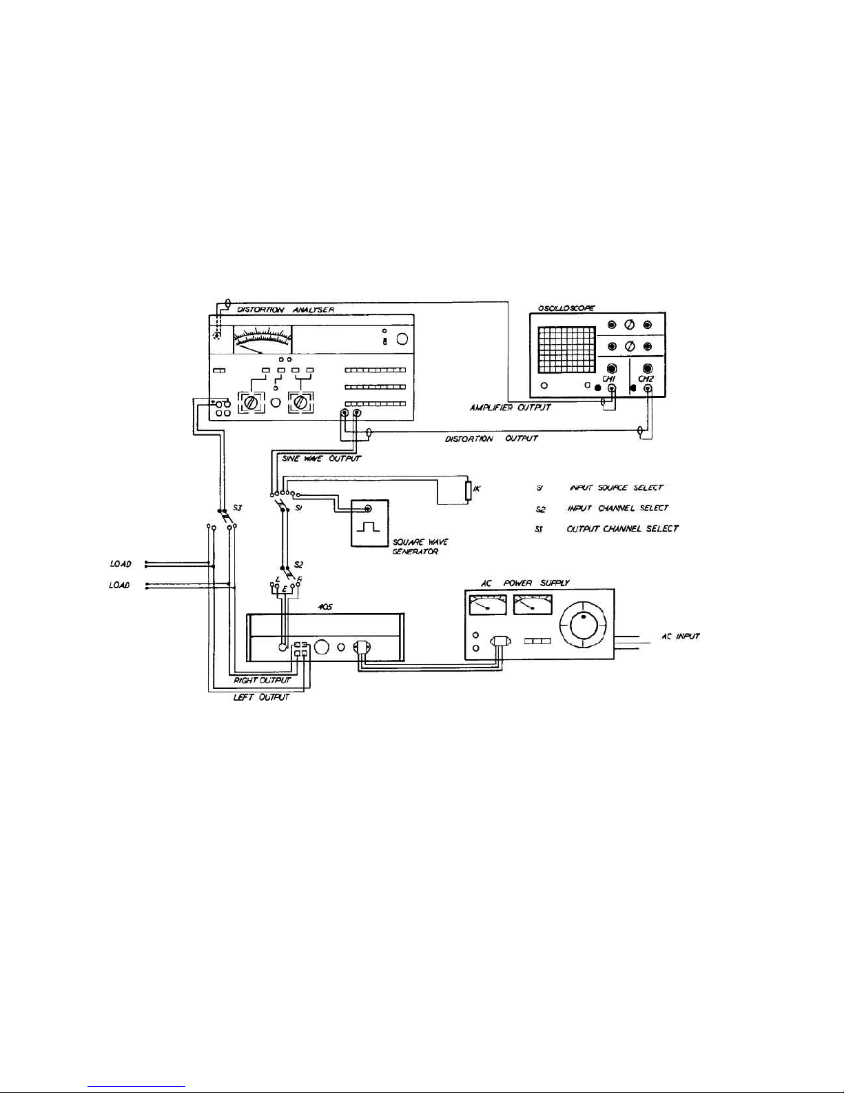
Select:
Controls Y1 - 0.5V/cm d.c. coupled
Timebasë 0.2 ms/cm
ST 17OOA- Volts/power 100W RMS
Distortion Ratio 0.01%
8OkHz and 400Ï filters both in
Frequency 1Ï
Low Distortion
Osc. level minimum
Connections Load 8„
Sl Sine Wave (STl7OOA)
S2 Left Input
S3 Left Output
If Á Amplifier fails any of t˙ë following tests, refer to Á appropriate pårt of Á fault finding section, page 6.
2.
3.
4.
5.
6.
7.
8.
9.
10.
11.
12.
13.
Check inside Á amplifier for obvious faults such as burnt components, blown internal fuses etc.
Each of Á following checks should be repeated on t˙ê oÁr channel.
Apply Á a.c. Supply Volts whilst observing Á current consumption which should not exceed 0.12A.
Increase thé oscillator level to 0.5V RMS ±0.5Î. Á output should be 100W with no sign of clipping.
Select set level ¶ adjust meter deflection for zero. Select distortion which should be less than 0.01%
Select volts/power, decrease Á applied frequency to 100Hz, remove 400Hz filter ¶ adjust
osciIIoscope timebase to 2ms/cm. Set level, select distortion which should be less than 0.01%. Select
volts/power, increase Á applied frequency to 3Ï, select 400Ó filter and adjust timebase to
50µs/cm. Select distortion which should again be less than 0.01%.
Select volts/power, increase applied frequency to 10kHz and adjust timebase to 20µs/cm. Adjust
oscillator level so that output is 100W. Set level Án select distortion which should be less than 0.05%.
Select volts/power,increase applied frequency to 20kÓ and adjust Á timebase to 10µs/cm. Reduce
output level to 80W. Set level and measure distortion which should be less than 0.1%.
Select volts/power and decrease frequency to 1kHz. Adjust oscillator level so that output is 100W and
adjust timebase to 0.2ms/cm. Û following checks are to monitor Á low frequency roll off of Á 405.
Select 30Ó and Á output level should fall by approximately 0.3dB. Select 20Hz and Á output level
should fall by approximately 1Î. Select 10Ó and Á output level should fall by 7dB ± 1.5dB.
Increase frequency to 1Ï. For 405s with amplifier boards type M12368 insert 1.8k„ voltage limiting
resistors into Á mini sockets on each amplifier board. For 405s with amplifier boards type M12565-3
insert a link into Áse sockets. Û output waveform should indicate clipping. Reduce Á oscillator level
until Á clipping just disappears at which point Á output level should be 20V RMS ±1V. Remove voltage
voltage limitters, and adjust oscillator level for 100W output.
Select volts/power ¶ square wave input, (S1). Adjust timebase to 0.1ms/cm. Remove load and note
Á difference in Á waveform with load and no load. Áre should be a slight difference in gain (10mV) but
no overshoot. Reconnect the 8„ load.
Û following checks should be carried out with no input signal and Á input to thë amplifier board loaded by
a 1k„ resistor, (S1). Remove 400Hz filter and select noise which should bê better than -93Î unweighted.
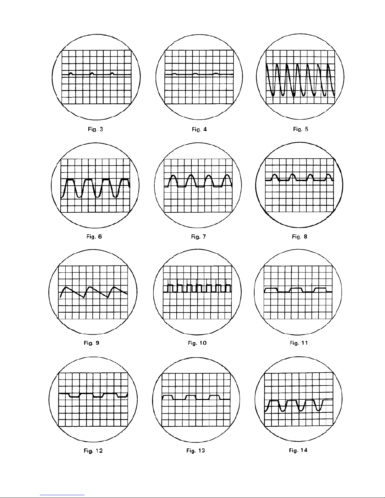
Select volts/power, 400Hz filter and sine wave input at å frequency of 1Ï and adjust oscillator
level for 100W output. Select 1„ load. Á output should clip equally on both halves of th´ waveform as
5
shown in Fig. 11.
Select 4„ load, output level should be 70W just prior to clipping.
CLAMP CIRCUIT TESTING
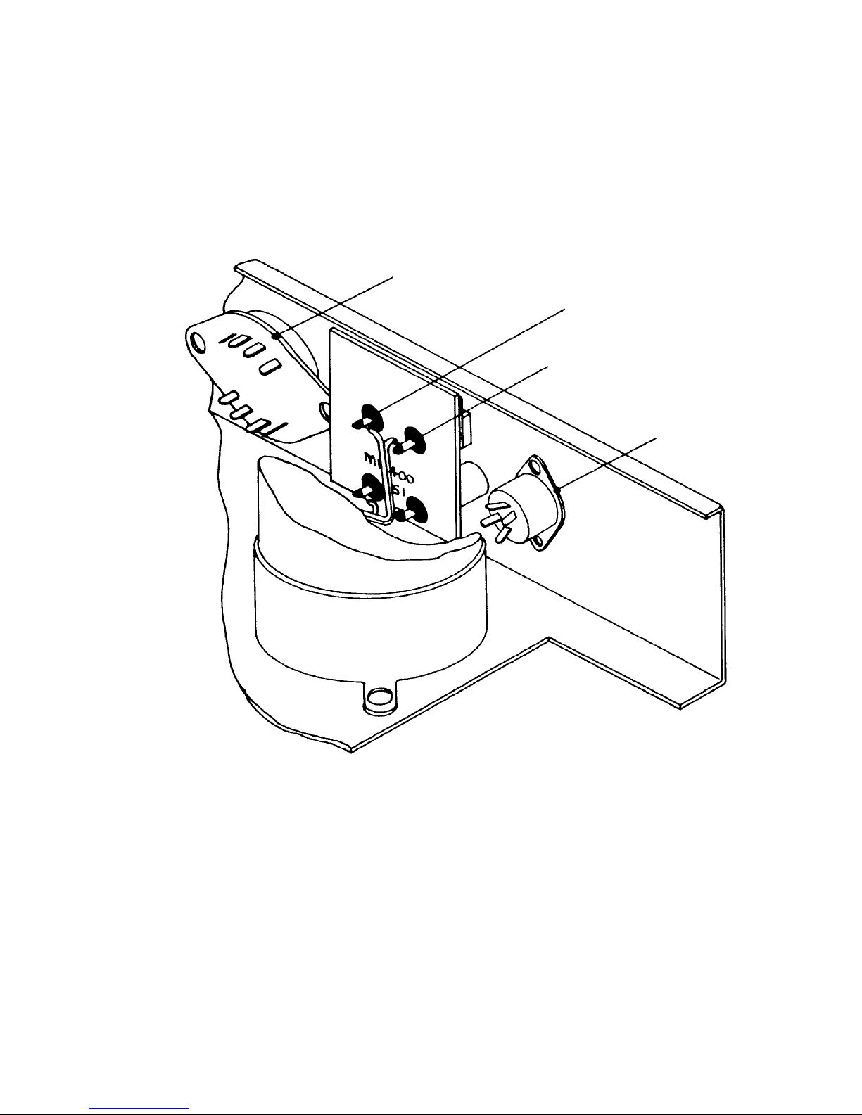
ln order to test Á clamp circuit, Á circuit should first be disconnected from its amplifier board, äs
described on page 4.
For 405s fitted with amplifier boards M12368 apply 6V d.c. across Á output terminals of Á relevant
channel with an ammeter in circuit.
For 405s fitted with amplifier boards M12565 ä wire should be soldered across Á back of Á amplifer board as
shown in Fig. 18(B). 6V d.c. should be applied between this wire and Á black output terminal of Á relevant
channel, with an ammeter in circuit.
In both cases Á current should not exceed 0.5mA. Reverse thë polarity of Á supply and repeat Á test.
Û test should Án be carried out on Á oÁr channel.
T˙ê complete test should thén be repeated using a 12V d.c. supply with a 10„ resistor in series, when Á
current should be approximately 1A.
1.
Y2 - 0.1V/cm d.c. coupled
Reproduced in pdf format
by Keith Snook
d.c.~daylight ltd. 2002