Haydon IDEA User manual

IDEATM PROGRAMMABLE
BRUSHLESS MOTOR DRIVE
MANUALS
CONTENTS:
HARDWARE MANUAL
SOFTWARE MANUAL
COMMUNICATIONS MANUAL

2
Table of Contents
Revision History ................................................................................................................. 3
Introduction......................................................................................................................... 4
Specifications...................................................................................................................... 5
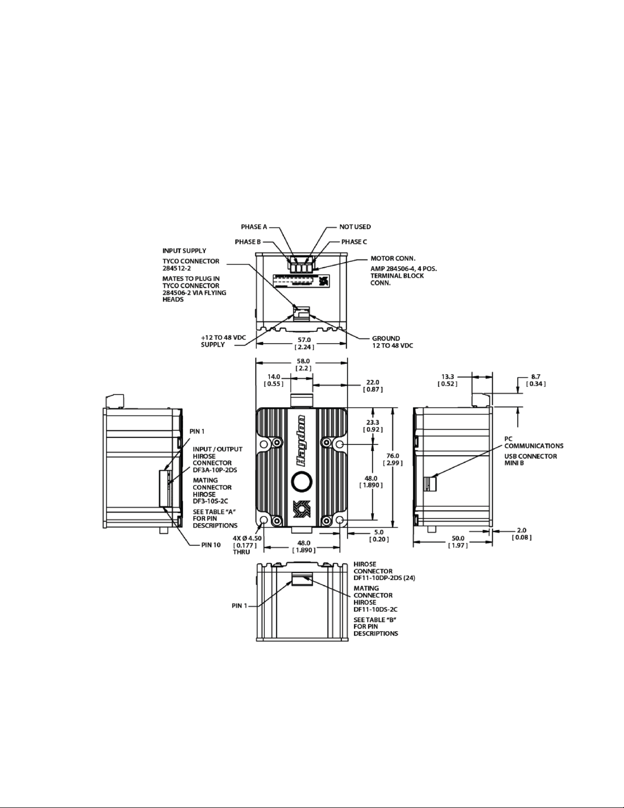
Engineering Drawings ........................................................................................................ 6
Connections......................................................................................................................... 7
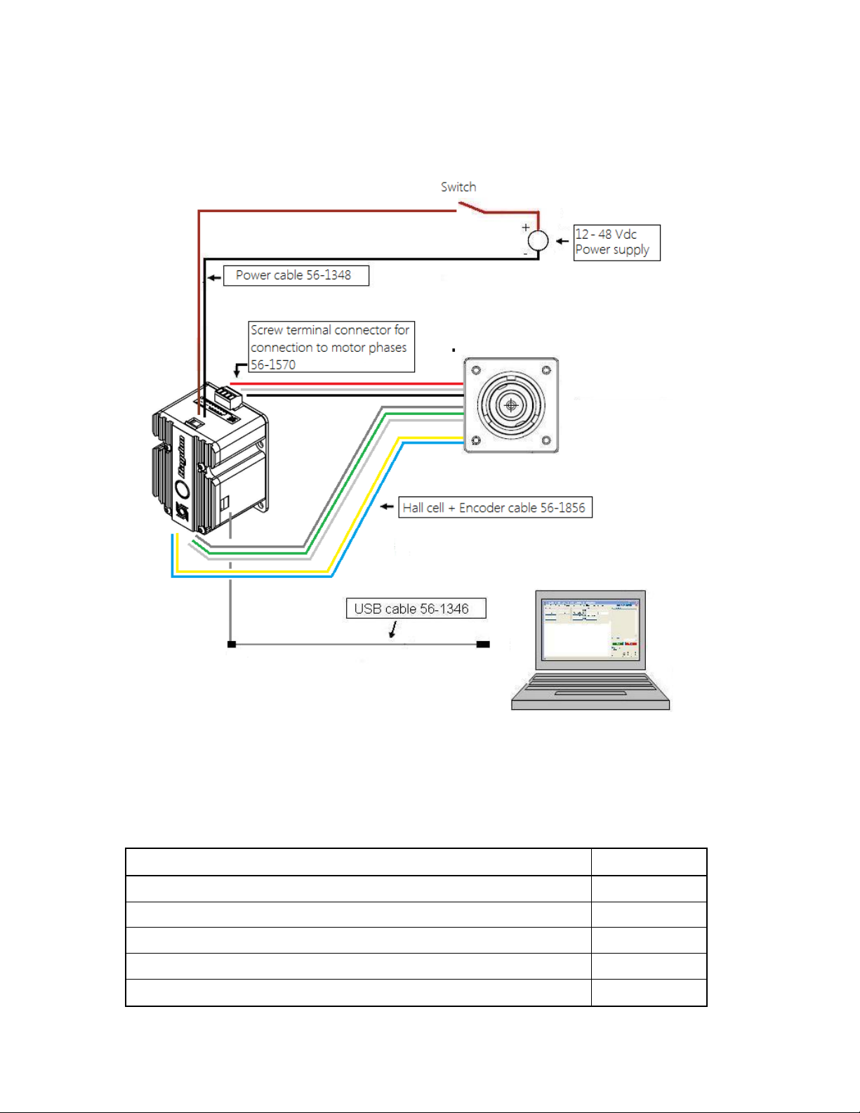
Basic Wiring Diagram ........................................................................................................ 8
Accessories ......................................................................................................................... 8
Encoder Inputs .................................................................................................................... 9
Encoder Wiring................................................................................................................. 10
Hall Cell Inputs................................................................................................................. 11
Hall Cell Wiring................................................................................................................ 11
Digital I/O Pin Descriptions.............................................................................................. 12
Open Collector Output Pin Description............................................................................ 12
Input Pin Description........................................................................................................ 12
Digital I/O Wiring............................................................................................................. 13
Digital Output Wiring Examples...................................................................................... 14
Digital Input Wiring Examples......................................................................................... 14

3
Revision History
Date
Description
January 2015
Initial version

4
Introduction
This manual is intended to provide basic hardware specifications for the Haydon
Kerk Brushless IDEA drive. For detailed information on use and programming of
the drive, please refer to the IDEA Drive User’s Manual. For detailed information
on the command structure of the drive for coding purposes, please refer to the
IDEA drive Communication Manual. All manuals are available at idea-drive.com.

5
PBL4850E
IDEA™ Drive
Specifications
Attribute
Value
Drive Input Voltage Range
12 – 48 VDC
Maximum Drive Current (per phase)
4.0 Arms (Up to 6.5 Apeak
current boost capability during
ramping)
Motor Type
3 Phase Brushless
Commutation Type
Sinusoidal with Hall Cell
Initialization
Hall Cell Spacing
60°/ 120°
Type of Ramping
Trapezoidal
S-Curve
Communications
USB (Mini B connector)
Digital I/O Voltage Range
5-24Vdc
Digital Inputs
4
Digital Sinking Outputs
4
Digital Output Maximum Sinking Current
200mA (each)
Digital Input Maximum Current
8mA (each)
Maximum Temperature
70ºC (Measured at heat sink)
Program Storage Size-Type
85 Kbytes-Flash
Maximum Number of Stored Programs
85, Referenced by 10
character program names
Position counter range
64bit
Interrupt sources
4 inputs (rising, falling or both
edges), internal position
counter (when reaching a
programmed position).

6
PBL4850E
IDEA™ Drive
Engineering Drawing
Engineering Drawings

7
Connections
Basic Wiring:To connect power to the drive and control it with the IDEA Drive
User Interface you will need the following:
•A power supply, minimum of 12VDC.
•A PC
•Power cable ( available from Haydon Kerk p/n 56-1348)
•Hall cell / Encoder harness (available from Haydon Kerk p/n 56-1856)
•Motor connected with screw terminal block ( available from Haydon Kerk
p/n 56-1570
•10 wire I/O cable (available from Haydon Kerk p/n 56-1352).
oNote: this cable is only required if the drive is interacting with an
external device.
•USB to Mini B USB cable ( available from Haydon Kerk p/n 56-1346 )
The following page contains the proper wiring diagram for the IDEA drive, power
supply and PC. The I/O and encoder cables are omitted.

8
Basic Wiring Diagram
Accessories
Accessories
Part No.
USB Cable (A to mini B), 2 meters
56-1346
Power Cable, 1 meter
56-1348
I/O Cable, 1 meter
56-1352
Motor Connector Screw Terminal
56-1570
Hall Cell & Encoder Cable
56-1856

9
Encoder Inputs
The IDEA drive is equipped with inputs for a single-ended, Quadrature
encoder attached to the motor it drives. Quadrature encoders have 2 output
signals, A and B, which are nominally 90 electrical degrees out of phase. On
each rising or falling edge, the relative logic levels of the two phases can be used
to determine the direction of rotation. The decoder within the drive interprets A
leading B as motion in the clockwise direction, as viewed from the front face of
the motor. This means that if a rising edge is detected on phase A, and phase B
is at a logical high, then the motor just rotated counter-clockwise.
The IDEA drive watches for the rising and falling transitions on phase A
and B, and increments or decrements the position counter accordingly. Using this
method, a 1000 cycle per revolution optical rotary encoder would have 4000
counts per revolution.

10
Encoder Wiring
The encoder connector can be wired to any 2 channel quadrature encoder
that operates between 3.3Vdc and 5Vdc. For encoders that work on 5VDC,
power to the encoder can be supplied through pin 4 of the encoder connector,
otherwise a separate 3.3Vdc power supply is required. Whether or not power is
being supplied by the drive, pin 5 must be connected to the same ground as the
encoder. This is internally connected to the IDEA drive’s ground connection.
Pin 3 is for encoders with an index signal. This may be left unconnected, and is
for future revisions which may make use of the index signal.
Pins 1 and 2 are the A and B connections, respectively. When the output
shaft of the motor is rotating clockwise as viewed from the front of the motor
phase A should lead phase B. Check your encoder’s documentation to check if A
and B need to be swapped, which can also be performed via software.

11
Hall Cell Inputs
The brushless IDEA drive uses sinusoidal commutation and utilizes the
hall cells for phase initialization. The IDEA drive accepts hall cell spacing
configurations of 60°and 120°. Please follow the wiring diagram which came with
the drive and motor combination for proper commutation and ideal motor
performance.
Hall Cell Wiring

12
Digital I/O Pin Descriptions
Open Collector Output Pin Description
Input Pin Description

13
Digital I/O Wiring
The IDEA drive has four optically isolated inputs and four optically
isolated, open-collector outputs. A power supply is necessary to activate the
opto-isolators with a voltage range of 5-24VDC. As the outputs are open-
collector, they will need a pull-up resistor tied to the + I/O supply if a high level
voltage is required. The outputs are capable of sinking up to 200mA each.
Note: The inputs can be used in two ways. They can be connected to logic levels
that swing between I/O supply ground and + I/O supply, or they can be attached
to a switch connected to I/O supply ground. In the second configuration, when
the switch is open, the drive will see this as a logic high, when the switch is
closed, and the input is connected to I/O supply ground, the drive will see this as
a logic low.
Note: When an input is connected to a mechanical switch or relay, a
phenomenon called “bounce” can occur. When the switch contact is almost
closed, several electrical arcs can form. If an input is being used as an interrupt,
each arc will be seen as a rising and falling edge, causing several false interrupts
to trigger. Any input being used as an interrupt source should only be attached to
solid state devices or a switch with de-bounce circuitry.

14
Digital Output Wiring Examples
Digital Input Wiring Examples

2
Table of Contents
Revision History............................................................................................................. 4
Introduction..................................................................................................................... 5
IDEA DRIVE and Software Basics ............................................................................. 6
Realtime Mode............................................................................................................ 6
Program Mode............................................................................................................. 7
Startup............................................................................................................................... 9
Installing the Application......................................................................................... 9
Getting Started.......................................................................................................... 10
Drive Startup ............................................................................................................. 13
Features and Concepts.............................................................................................. 14
Unit conversion ........................................................................................................ 14
View Command String............................................................................................ 15
Communications Modes ........................................................................................ 15
Maximum Speed....................................................................................................... 17
Ramping ..................................................................................................................... 18
Encoder....................................................................................................................... 19
Saving Programs to the Drive .............................................................................. 22
Removing Programs ............................................................................................... 22
Table of Contents..................................................................................................... 22
Startup Program....................................................................................................... 23
Saving/Loading/Combining Programs............................................................... 23
Autosave..................................................................................................................... 23
Over Current Protection......................................................................................... 24
Accel/Decel Current Boost.................................................................................... 24
Password Protection............................................................................................... 24
Inputs and Outputs.................................................................................................. 25
Simulating Inputs................................................................................................. 26
Debugger.................................................................................................................... 26
Subroutines............................................................................................................... 27
Interrupts.................................................................................................................... 28
Errors........................................................................................................................... 30
Explanation of Commands........................................................................................ 32
Extend......................................................................................................................... 32
Retract......................................................................................................................... 34
Move To ...................................................................................................................... 36
Go At Speed............................................................................................................... 38
Stop.............................................................................................................................. 40
E-Stop.......................................................................................................................... 41
Jump N Times........................................................................................................... 42
Goto............................................................................................................................. 43
Goto If.......................................................................................................................... 44
Return.......................................................................................................................... 45
Return To.................................................................................................................... 46
Goto Sub..................................................................................................................... 47

3
Wait.............................................................................................................................. 48
Wait For Move........................................................................................................... 49
Int on Pos................................................................................................................... 50
Int on Input................................................................................................................. 51
Encoder....................................................................................................................... 53
Set Outputs................................................................................................................ 54
Set Position ............................................................................................................... 55
Reset............................................................................................................................ 56
Abort............................................................................................................................ 56
Comment.................................................................................................................... 57
Programming Examples............................................................................................. 58
Example One............................................................................................................. 58
Example Two............................................................................................................. 62
Example Three.......................................................................................................... 64
Example Four............................................................................................................ 68
Example Five............................................................................................................. 71
Example Six............................................................................................................... 76
The IDEA Drive Menu Items....................................................................................... 80
File................................................................................................................................ 80
Edit............................................................................................................................... 80
Mode............................................................................................................................ 80
Drive Commands...................................................................................................... 81
Communications Mode........................................................................................... 81
Programs on Drive................................................................................................... 81
Help.............................................................................................................................. 82
Glossary ......................................................................................................................... 83

4
Revision History
Date
Description
January 2010
Initial version
February 2010
Save debug output
Goto if updated for outputs
Interrupt and encoder configuration update
January 2011
Added detail to the behavior of interrupts
Added detail to the IO wiring diagram
Stand alone IO wiring diagram
RS-485 wiring
Communications features
May 2011
Added RS-485 Pin descriptions
Added minimum time between resets
July 2011
Removed model specific information
August 2011
Added information about command strings
September 2011
Updated for 2.0 firmware and software changes
Added introduction and part number information
December 2011
Clarified Goto if explanation Updated
March 2013
Clarified part number entry
January 2015
Revised manual for brushless IDEA drive

5
Introduction
This manual is intended to provide information on using the Brushless IDEA drive
from Haydon Kerk Motion Solutions. For information pertaining to a specific
product, see the appropriate hardware manual, available at haydonkerk.com
Table of contents
Popular DC Drive manuals by other brands

Rockwell Automation
Rockwell Automation Allen Bradley Kinetix 7000 2099-BM06-S Design guide

Danfoss
Danfoss FC 100 Series manual

Siemens
Siemens SIMOREG DC-MASTER operating instructions

GFA
GFA 10003166 10011 installation instructions

Parker
Parker Compax3H C3H1xxV4 Series installation manual

Control Techniques
Control Techniques Emerson Focus 1 user guide

Mars
Mars Comfort-aire Century HBH Series Installation, operation & maintenance manual

Siemens
Siemens SINAMICS S110 Function manual

Danfoss
Danfoss VLT Brake Resistor MCE 101 Design guide

Alutech
Alutech Targo R-5024-400 Assembly and operation manual

YASKAWA
YASKAWA GA80U4720ABM manual

Dorner
Dorner 2200 series Installation, maintenance & parts manual