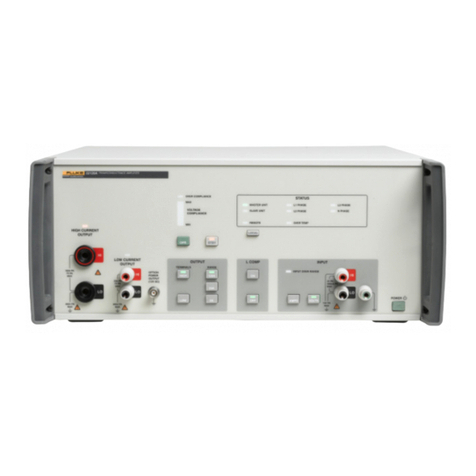
HBK 2755 User manual


HEALTH AND SAFETY CONSIDERATIONS
This apparatus has been designed and tested in accordance
with IEC/EN 61010 – 1 and ANSI/UL 61010 – 1 Safety
Requirements for Electrical Equipment for Measurement,
Control and Laboratory Use. This manual contains
information and warnings which must be followed to ensure
safe operation and to retain the apparatus in safe condition.
Safety Symbols and Signal Words Used
The apparatus will be marked with this symbol
when it is important that you refer to the
associated danger or warning statement given in
this manual
The manual uses this symbol when a danger or
warning statement is applicable
Hazardous Voltage/Electricity. Both the
apparatus and manual use this symbol when
there is a risk for shock or electrocution
Hot Surface. This manual will use this symbol
when there is a risk for burning or scalding
Earth (Ground) Terminal. The apparatus will be
marked with this symbol when applicable
Protective Conductor Terminal. The apparatus
will be marked with this symbol when applicable
Alternating Current. The apparatus will be marked
with this symbol when applicable
Danger Signals an imminent hazardous situation, which, if
not avoided, will result in death or serious injury
Warning Signals a possibly hazardous situation, which, if
not avoided, will result in death or serious injury
Caution Signals a hazardous situation, which, if not
avoided, could result in minor or moderate injury
or damage to the apparatus
Notice Signals a situation or practice that requires
attention, but does not directly result in personal
injury if ignored
Risks and Hazards
Explosion Hazards
Danger: The apparatus is not designed to be used
in potentially explosive environments. It should
not be operated in the presence of flammable
liquids or gases
Electrical Hazards
Warning: Any adjustment, maintenance and
repair of the open apparatus under voltage must
be avoided as far as possible and, if unavoidable,
must be carried out only by trained service
personnel
Electrical Hazards
Warning: The apparatus is capable of producing
hazardous output voltages. To avoid electrical
shock, do not touch any exposed loudspeaker
wiring while the apparatus is operating
Caution: The apparatus is very powerful and can be
potentially dangerous. Many loudspeakers can
easily be damaged or destroyed by applying too
much power. Always check the loudspeaker’s
continuous and peak power capabilities
Caution: The mains voltage selector on the rear panel
indicates the AC mains voltage. Before
connecting the mains power cable, ensure that
the mains voltage selector is set to your mains
power voltage. The warranty will not cover
damage caused by connecting to the wrong type
of AC mains power

Precautions During Operation
• Heed all warnings.
• Follow all instructions.
• Do not use this apparatus near water. Do not spill water
or other liquids into or on the apparatus. Do not operate
the apparatus while it is wet or standing in liquid.
• Clean only with a dry cloth.
• Do not operate the apparatus near any heat-producing
devices such as radiators, heat registers or stoves.
• Always operate the apparatus with the chassis
connected to the electrical safety earth using a proper
mains cable. Do not diminish the safety purpose of a
grounding-type plug, which besides two pins has 1 or 2
grounding contacts, provided for your safety. If the
provided plug does not fit into your outlet, there may be
a fault with the power cable provided – contact HBK.
• Connect only to AC power outlets rated 230 V (ranging
from 170 to 264 V) or 115 V (ranging from 85 to 132 V),
45 to 65 Hz (check the proper nominal voltage at the
back of the apparatus.
• Do not use this apparatus if the power cable is broken or
frayed. Protect the power cable, do not stand on it or
pinch it, particularly at the plug and the point where it
meets the apparatus.
• Do not connect either of the speaker output terminals to
ground.
• Do not block the air inlet or air outlet aperture. Install the
apparatus in accordance with instructions.
• Only use accessories specified by HBK.
• Unplug the apparatus during lightning storms or when
not in use for long time periods.
• The input and output signals must comply with the
specifications given in Chapter 4.
• Do not connect an apparatus output in parallel or series
with any other apparatus’ output. Do not connect the
apparatus output to any other voltage source, such as
battery, mains source, or power supply, regardless of
whether the apparatus is turned on or off.
• Do not run the output of any apparatus back into another
channel’s input.
• Refer all servicing to qualified service personnel.
Servicing is required when the apparatus has been
damaged in any way.
• Do not remove the housing, the inner top cover or the
front panel. Removal of any of these components will
expose hazardous voltages. There are no serviceable
parts inside and removal may void the warranty.
• An experienced user should always supervise the use of
this professional audio equipment, especially if
inexperienced adults or minors are using it.
WASTE HANDLING
HBK complies with the EU’s Waste Electrical and
Electronic Equipment (WEEE) Directive, which issues
the following waste handling instructions:
• Do not dispose of electronic equipment or
batteries as unsorted municipal waste
• It is your responsibility to contribute to a clean
and healthy environment by using the
appropriate local return and collection systems
• Hazardous substances in electronic equipment
or batteries may have detrimental effects on the
environment and human health
• The symbol shown to the left indicates that
separate collection systems must be used for
any discarded equipment or batteries marked
with that symbol
• Waste electrical and electronic equipment or
batteries may be returned to your local HBK
representative or to Hottinger Brüel & Kjær A/S
for disposal

HBK has made every effort to ensure the accuracy of the
information contained in this document. No responsibility is
accepted for any errors or omissions herein. It is the
responsibility of the user to ensure compliance with any legal or
statutory requirements in the country of use. Data may change,
as well as legislation, therefore you are advised to obtain copies
of the most recently issued applicable regulations, standards
and guidelines.
All descriptions, illustrations and any other information relating
to the product are made by way of general description, are
approximate only and for the general guidance and information
of the user. They cannot be construed to imply representation or
warranty as to their accuracy, currency or completeness and are
not intended to form the basis of any contract.
The information in this document does not constitute a
warranty, representation or guarantee concerning the suitability
or performance of the product.
HBK shall not be liable for any loss whether direct, indirect,
incidental or consequential arising from the use of or reliance
upon any of the content of this document, regardless of whether
such content has been accurate or complete. HBK will not pay
any damages whether for loss or injury, punitive or otherwise,
because of use of or reliance upon any of the content in this
document.
Brüel & Kjær and all other trademarks, service marks, trade
names, logos and product names are the property of Hottinger
Brüel & Kjær (HBK) or a third-party company. Nothing in this
document may be construed as granting, by implication, or
otherwise any license or right to use any of the trademarks
without a prior written permission of HBK or the owner of such
trademark.
© Hottinger Brüel & Kjær A/S. All rights reserved.
Teknikerbyen 28 · DK-2830 Virum · Denmark
Telephone:+4577412000·Fax:+4545801405
For service and support, contact your nearest HBK Global
Customer Care (GCC) team:
China (Shanghai): info@bksv.com.cn,
+862161133674
France: service.fr@bksv.com, +33 1 69 90 71 01
Germany: GCC_DACH@hbkworld.com, +49 421 1787 0
Italy: service.it@hbkworld.com, +39 02 45471616
Japan: info_jp@bksv.com, +81 3 6810 3500
+1 770 209 6907
Spain: servicio.es@hbkworld.com, +34 91 806 2610
British Isles: ukservice@bksv.com,+441223389800
To learn more about all HBK offerings, please visit:
www.hbkworld.com

Contents
CHAPTER 1
Overview .................................................................................................................................................................... 1
1.1 About this Manual............................................................................................................................. 1
1.2 Important Safety Instructions .......................................................................................................... 1
1.3 About the Amplifier........................................................................................................................... 1
1.4 Documentation.................................................................................................................................. 2
CHAPTER 2
Description ................................................................................................................................................................ 3
2.1 Front Panel ........................................................................................................................................ 3
2.2 Display Overview............................................................................................................................... 5
2.3 Rear Panel ......................................................................................................................................... 9
2.4 Side Panel........................................................................................................................................ 10
CHAPTER 3
Installation............................................................................................................................................................... 11
3.1 Setting Up the Amplifier Hardware ................................................................................................ 11
3.2 Setting Up the Amplifier Software ................................................................................................. 14
CHAPTER 4
Operation ................................................................................................................................................................. 17
4.1 Powering Up .................................................................................................................................... 17
4.2 Menu ................................................................................................................................................ 18
4.3 Presets............................................................................................................................................. 19
4.4 Audio Inputs .................................................................................................................................... 20
4.5 Audio Outputs ................................................................................................................................. 23
4.6 Audio USB Port................................................................................................................................ 27
4.7 Level Control & Display................................................................................................................... 27
4.8 Signal Generator ............................................................................................................................. 31
4.9 Web Server ...................................................................................................................................... 33
4.10 Fans ................................................................................................................................................. 36
CHAPTER 5
Maintenance, Service and Repair........................................................................................................................... 37
5.1 General Maintenance Instructions................................................................................................. 37
5.2 Cleaning the Air Filter ..................................................................................................................... 37
5.3 Protection Features ........................................................................................................................ 38
5.4 Replacing the Fuse ......................................................................................................................... 39
5.5 Troubleshooting.............................................................................................................................. 39
5.6 Service ............................................................................................................................................. 40

CHAPTER 6
Specifications ......................................................................................................................................................... 41
INDEX........................................................................................................................................................... 47

1
Chapter 1
Overview
1.1 About this Manual
This manual contains important information on setting up and operating your HBK 2755/2755-A Smart
Power Amplifier correctly and safely. Please take the time to read this manual and familiarize yourself with
the safety considerations and advanced features.
1.2 Important Safety Instructions
Before using your amplifier, carefully read through the Health and Safety Considerations at the beginning
of the manual.
HBK provides a mains cable with IEC connector for the amplifier's mains socket and a moulded mains plug
on the other end. The mains plug will be appropriate for the country where the amplifier was ordered.
⚠WARNING: For safe operation, ensure that the mains outlet is equipped with an earth connection
and that the protective earth conductor is not interrupted in any way. Do not use
extension cables without protective earth conductors. See also Chapter 3.
1.3 About the Amplifier
The amplifier is available in two versions:
•HBK 2755: Includes Wi-Fi®, allowing you to configure and control the amplifier from a smart device
through partitions in a building when needed
•HBK 2755-A: Does not include Wi-Fi and is only operated by controls on the front panel
This manual uses the term ‘the amplifier’ to refer to both versions. Where there is a difference in features
or usage, the individual type number will be used.
1.3.1 Description
The amplifier provides high-quality amplification and signal generation in one small, lightweight package.
Designed for building acoustic measurements in the field, it has easy-to-access ports and includes a
wireless control option (HBK 2755). The calibrated dials and indicators allow setups to be easily
reproduced in future tests. The main functions are readily available upon power up, while additional
functions and settings are accessible through a menu on the display.

HBK 2755 Smart Power Amplifier – User Manual2
1.3.2 Functional Diagram
Fig.1.1 The functional diagram of the amplifier
The amplifier contains a signal generator, input conditioners, a USB/audio interface and an audio signal
mixer that routes combined signals to the USB and the attenuator. The attenuated signals are fed to a level
monitor, a loudspeaker power stage and a line output stage.
The audio functions are controlled digitally, enabling multiple ways of using the amplifier. At power up these
functions adopt common settings and the unit is ready for typical use. Additional settings are available
through the menu on the display, and with HBK 2755 via Wi-Fi using a connected device. All settings can be
saved and loaded as presets.
For information about setting up the amplifier via the menu, go to section 4.2.
1.4 Documentation
To view the latest supporting documentation on the amplifier, including embedded help and safety and
warranty information, go to https://www.bksv.com/2755-manuals.
1+
1–
2+
2–
Signal
Generator
12
3
RT
Line Out
Power Out
XLR
TRS Phone Jack
BNC
BNC
speakON
Signal
Level
Monitor
USB/Audio
Interface
Mixer Aenuator
Control and Display
Input
Power Supplies
and
Amplifiers
S
Line or Mic In
30dB
5
Line Out
Stage
Power
Stage
220032

3
Chapter 2
Description
2.1 Front Panel
The figure below shows all control, display and connector functions. See the table for descriptions.
Fig.2.1 Overview of the front panel
✐Please note: Most of the front panel functions described below depend on menu settings that are volatile and will
return to their default values upon switching on the amplifier. Exceptions are the amplifier mode, the
network settings, the menu language, the brightness of the indicators, and settings in a particular
preset, named Startup, which are non-volatile and considered part of the installation (see section
3.2).
4
610
5
30dB
5
123
789 11 12
220033

HBK 2755 Smart Power Amplifier – User Manual4
NUMBER COMPONENT DESCRIPTION OPERATION
INSTRUCTION
1 Generator button*1 Toggles white noise (in 4292-L mode) or LF noise (in
4250 VVS mode) on and off.
When active, the indicator above the button
illuminates white
See section 4.8
2 Generator button*2 Toggles pink noise (in 4292-L mode) or MF noise (in
4250 VVS mode) on and off.
When active, the indicator above the button
illuminates pink
See section 4.8
3 Generator button*3 Toggles equalized noise (in 4292-L mode), HF noise
(in 4250 VVS mode) or a user-selected signal (from
“User signal” menu) on and off.
Default signals are equalized noise or HF noise
(indicator colour when active: light-green). With a
user signal selected, the indicator will illuminate light
blue when active
See section 4.8
4 Display In Operational mode: Shows the level indicator,
attenuation and status bar
In Menu mode: Shows menu selection
See section 4.7
for level and
attenuation
information
5MainspowerswitchSwitchesamplifier power on and off
NOTE:To ensure the switch is fully engaged in the left
or right position, use quick, deliberate movements
See section 3.1
6 Input signal Neutrik®
combo jack connector
Accepts both a balanced XLR and a ¼-in TRS phone
jack plug. The XLR input is balanced and features an
input amplifier and a phantom power supply with
phantom power indicator above the socket.
The TRS input can be configured as single-channel
balanced or dual-channel unbalanced
See section 4.4
7InputsignalBNC
connector
Features an input amplifier and an IEPE power supply
with IEPE power indicator above the socket
See section 4.4
8 Output signal BNC
connector
Line-level output. The signal from this socket is a
basic mix of the internal generator, input and USB
signals
See section 4.5
9 Attenuator selector
or Menu selector
Dual-purpose selector (hold down to toggle):
• Operational mode: Sets the amplifier attenuation,
shown as a negative gain in dB
• Menu mode: Scrolls through the menus. Press to
select a menu item
See section 4.2
and section 4.7

CHAPTER 2
Description 5
2.2 Display Overview
2.2.1 Operational Display
At power up, the display is in Operational mode and will show the level indicator, the attenuation and status
bar.
There are two operation modes: 4292-L mode ( ) and 4250 VVS mode ( ).
Fig.2.2
Display: Operational mode.
Left: 4292-L mode
Right: 4250 VVS mode
10 USB-C connector Audio interface to the host computer†. The USB
indicator above the socket illuminates when the
interface is active. When connected to the PC, the
amplifierturns intoa‘powersounddevice’with6)and
7) providing versatile audio inputs and 8) and 11)
providing versatile audio outputs
See section 4.6
11 Output signal (Neutrik
speakON®connector
Power output to loudspeakers. Provides a balanced
high-power output or two separate unbalanced
moderate-power outputs
See section 4.5
12 Mains power socket Above the socket is the fuse drawer that contains
both the operational mains power fuse (T5A) and a
spare fuse
See section 3.1
and section 4.1
* Generator signals are mutually exclusive, only the most recently selected button is active
† Connecting to a host computer is optional and not the typical setup
NUMBER COMPONENT DESCRIPTION OPERATION
INSTRUCTION
Level
Aenuaon
Status bar 30
dB
5
30
dB
5
DEFGHC
CB
B
A
220034

HBK 2755 Smart Power Amplifier – User Manual6
NUMBER SYMBOL MEANING DESCRIPTION MORE
INFORMATION
A Attenuation locked Avoids attenuation changes due to unintentional
contact
See section 4.7.1
B Wi-Fi mode (HBK 2755 only) Shows Wi-Fi activity (Off/Station/
Hotspot)
See section 3.2.3
and section 4.9
C Amplifier mode Selects 1 of 2 default internal noise signal sets upon
power up. 4292-L mode is optimized for use with an
omnidirectional source; 4250 VVS mode for usewith
a volume velocity source
See section 4.8
D Power compression on Stabilizes loudspeaker output power when using
internal noise generator: Constant power vs
Constant gain
See section 4.5.3
E Fan control overruled Avoids (changing) fan noise or provides maximum
cooling: fan On or Off versus Auto
See section 4.10
F Input changed At least one input deviates from default regarding
configuration, gain or power
See section 4.4
G Filter active At least one internal treble and/or bass filter deviates
from neutral
See section 4.5.3
H Output changed The power output deviates from Bridge mode
configuration,Constantgainor theattenuatorsettings
deviate from 0 dB gain limit
See section 4.5.1

CHAPTER 2
Description 7
2.2.2 Menu Display
Fig.2.3
Display: Menu mode. The
triangle at the bottom right
shows there are more menu
items
Holding down the large selector knob on the front panel (9), opens the Menu. To toggle back to Operational
mode without performing an action, hold down the selector.
An overview of the entire menu is provided below.
✐Please note: Most sub-level menus also include two items: Up (move up one level) and Exit (leave the menu, go
back to the attenuation display).
Table 2.1 Menu structure
Presets
Input
Bass/Treble
Output
User signal
Network
MAIN MENU SUB LEVEL LAST LEVEL MORE INFORMATION
Presets Load setup Select from actual list See section 4.3
Save setup Enter new setup name
Delete setup Select from actual list
Input XLR input gain 0, 10, 20 or 30 [dB] See section 4.4
BNC input gain 0, 10, 20 or 30 [dB]
Phantom power On or Off
IEPE power On or Off
TRS mode Differential or Single-
ended
Bass/Treble Bass gain Turn selector: [–18 to 18]
dB in steps of 3 dB
See section 4.5
Treble gain

HBK 2755 Smart Power Amplifier – User Manual8
Output Lock gain Enabled or Disabled See section 4.5
Output mode Bridge (highpower),Dual
channel, Single-ended
ch.1, Single-ended ch.2,
or Single-ended ch.1+2
Power compression Constant gain or
Constant power
Gain limit 0, –10, –20 or –30 [dB]
Gain step 1.0 or 0.5 [dB]
User signal – Select from list See section 4.8
Network (HBK 2755
only)
Wi-Fi mode Off, Station or Hotspot See section 3.2.3 and
section 4.9
Connect Select from actual SSID
list
Forget Select from actual SSID
list
Hotspot password Enter suitable password
Webserver Enabled or Disabled
Info SSID, IP address
Settings Fan control Auto, On or Off See section 4.10
Brightness Low or High See section 3.2.2
Language English See section 3.2.1
Mode 4292-L or 4250 VVS See section 4.8

CHAPTER 2
Description 9
2.3 Rear Panel
The red voltage selector at the rear panel toggles between a nominal mains voltage of 230 V and 115 V. The
QR code will take you to the product download page on the website (bksv.com/2755-manuals).
Fig.2.4 Rear panel of the amplifier (shown: HBK 2755)
About Version info Type number, serial
number, software
version number,
software version date,
API version number,
hardware version
number
See section 3.2.5
Software update
(HBK 2755 only)
Available update status
Help QR code to Help web
page URL
Legal notices QR code to Legal notices
web page URL
Exit – Leave the menu
230
00 0302
HBK 2755 Smart Power Amplifier
With Wi-F i
Serial No.
Mains V oltage
230 115 Vor / 45-65 HzAC
650 W - Fuse T5A
220036

HBK 2755 Smart Power Amplifier – User Manual10
2.4 Side Panel
The amplifier is equipped with a filter over the air intake. When the amplifier is used in dusty environments,
while demanding high power and intensive fan operation, the air filter is imperative, however the filter
reduces the fan cooling capacity somewhat. In clean environments, it can be removed to maximize
operating time (that is, without getting overheated) at high power.
Fig.2.5 Left side panel, with and without the air intake filter
22003
7

11
Chapter 3
Installation
CAUTION: The mains voltage selector on the rear panel indicates the AC mains voltage. Before
connecting the mains power cable, make sure the mains voltage selector is set to your
mains power voltage. The warranty will not cover damage caused by connecting to the
wrong type of AC mains power.
HBK provides a mains cable with IEC connector for the apparatus’ mains socket and a
moulded mains plug on the other end. The mains plug will be appropriate for the
country where the apparatus was ordered. If the provided plug does not fit into your
outlet, there may be a fault with the power cable provided – contact HBK.
⚠WARNING: For safe operation, ensure that the mains outlet is equipped with an earth connection
and that the protective earth conductor is not interrupted in any way. Do not use
extension cables without protective earth conductors. See information about
grounding in step 6) below.
Do not use this apparatus if the power cable is broken or frayed. Protect the power
cable, do not stand on it or pinch it, particularly at the plug and the point where it meets
the apparatus.
3.1 Setting Up the Amplifier Hardware
1) Place the amplifier horizontally or vertically.
2) Connect your external signal source to one of the input connectors on the front panel.
Inputs can be balanced or unbalanced and equipped with an input amplifier and/or power supply.
Compared to unbalanced signal connections, balanced connections are better able to cancel out AC
ground loop hum or picked-up radiated interference that might emerge with low-level signals. On the
other hand, unbalanced connections are usually simpler.
Signals from high-impedance devices or devices coupled to the mains power, directly or through
peripherals, may be disturbed in particular. In those cases, a balanced input may improve the transfer,
even from unbalanced source signals, if a proper connection cable is used.
See section 3.1.1 to find out more about balanced and unbalanced inputs.
✐Please note: The TRS input defaults to ‘Differential’ at power-up.

HBK 2755 Smart Power Amplifier – User Manual12
3) Connect an external device (sound recorder, voltmeter, external power amplifier, etc.) to the line output
connector.
✐Please note: The line output connector delivers low-level signals, while loudspeakers or sound sources typically
require high-power signal from the power output connector.
4) (Optional) Connect your PC to the USB connector.
5) Connect a loudspeaker to the power output connector.
At power-up, this Neutrik speakON output defaults to Bridge output mode, delivering maximally 500 W
(sine) into a 4 load (250 W into 8 ) at a limited duty cycle, or 300 W into 6 continuously from the
internal noise generator, such as with OmniPower™ Sound Source Type 4292-L.
In this mode, to provide a 1-channel output, connect the speaker wires + and – to pins 1+ and 1– of the
connector, as shown schematically below. The power outputs can drive loads down to 3 . The
operating voltage on pins 1+ and 1– ranges from –30 to 30 V. Therefore, to prevent electric shock, do
not operate the amplifier with any of the conductor portion of the speaker wire exposed.
NOTICE: Do not connect either of the speaker output terminals to ground.
Fig.3.1
Power output bridge
configuration and
associated speakON socket
connections
You can also set up a 2-channel output. See section 4.5.3 for setup instructions.
6) Unpack the mains cable from its separate cardboard box and connect it to the mains socket. Please
respect all warnings and instructions above.
1+
1–
2+
2–
220042
Table of contents
Other HBK Amplifier manuals


