HBK HBM Bruel & Kjaer AD103C User manual

AD103C
ENGLISH DEUTSCH
Operating Manual
Bedienungsanleitung

Hottinger Brüel & Kjaer GmbH
Im Tiefen See 45
D-64293 Darmstadt
Tel. +49 6151 803-0
Fax +49 6151 803-9100
www.hbkworld.com
Mat.:
DVS: A05895 01 X00 00
07.2022
EHottinger Brüel & Kjaer GmbH
Subject to modifications.
All product descriptions are for general information
only. They are not to be understood as a guarantee of
quality or durability.
Änderungen vorbehalten.
Alle Angaben beschreiben unsere Produkte in allge
meiner Form. Sie stellen keine Beschaffenheits- oder
Haltbarkeitsgarantie dar.

AD103C
ENGLISH DEUTSCH
Operating Manual

AD103C
TABLE OF CONTENTS
2
TABLE OF CONTENTS
1 Safety Instructions 3................................................
2 Markings used 5....................................................
2.1 Markings used in this document 5.....................................
2.2 Symbols on the device 6.............................................
3 Special features 7..................................................
4 Mechanical construction 8...........................................
5 Amplifier board Electrical configuration 9..............................
5.1 Function 10.........................................................
5.2 Signal conditioning 11................................................
5.2.1 Triggering 12........................................................
5.2.2 Limit value outputs 12................................................
5.2.3 Control inputs 12....................................................
5.2.4 Extreme values 12...................................................
5.2.5 Filling control 13.....................................................
5.2.6 Diagnostic function 13................................................
6 Electrical connection 14..............................................
6.1 Transducer connection 14.............................................
6.1.1 Connection in a 6-wire configuration 14..................................
6.1.2 Connection in a 4-wire configuration 15..................................
6.2 Connecting the supply voltage 16.......................................
6.3 Connecting the RS232 serial interface 17................................
6.4 Connecting CAN bus or DeviceNet 18...................................
6.5 Connecting the diagnostic interface 19..................................
6.6 Hardware switch for parameter protection 19............................
6.7 Connecting the digital inputs/outputs 20.................................
6.7.1 Hardware connection, signal level 20....................................
6.7.2 Function of limit value outputs and control inputs 22.......................
6.7.3 Function of inputs/outputs for dosing control (IMD2) 23....................
Index 24...................................................................

3
AD103C
SAFETY INSTRUCTIONS
1 SAFETY INSTRUCTIONS
Intended use
AD103C digital transducer electronics are part of the AED component family that digitally
conditions signals from mechanical measurement sensors and networks them with bus
capability.
These include digital amplifier boards, basic devices and intelligent sensors with inte
grated signal processing. It is the task of these components to directly digitize and condi
tion the measurement signals at the transducer location. Using digital transducer elec
tronics, you can directly connect Strain Gage (SG) transducers in a full bridge circuit to a
controller or PC. This enables you to configure complete measurement chains quickly
and with little extra work.
The AD103C amplifier board can be operated independently from the basic devices.
The AED basic devices provide mechanical protection, shield the AD103C amplifier
boards (EMC protection) and also allow you to select other interfaces in addition to the
RS232 serial interface, such as RS485 (4-wire), Profibus, CANOpen and DeviceNet.
The signal conditioning functions of limit value monitoring, extreme value memory and
fast-settling digital filters open up the door to further areas of application. In addition, the
AD103C enables you to control the filling and dosing processes.
The free PanelX PC software is provided for easy setting of all parameters, displaying
dynamic measurement signals, and comprehensive analysis of the dynamic system.
In this document, the AD103C transducer electronics are also referred to by the abbrevia
tion AED (Aufnehmer-Elektronik-Digital, digital transducer electronics).
The AD103C commands are compatible with the AD103B amplifier. The calibration func
tion (CAL, ACL commands) to ensure the accuracy of the AD103C is no longer needed.
However, these commands are still implemented to ensure software compatibility. The
AD103C no longer needs measurement interruption to ensure measurement accuracy.
Operating conditions
The design and safety features of the device must not be modified. Any modification will
void our liability.
SThere are no hazards associated with this product, provided the notes and instruc
tions for project planning, installation, correct operation and maintenance are
observed.
SEach time before starting up the equipment, you must first run a project planning and
risk analysis that takes into account all the safety aspects of automation technology,
especially in relation to the protection of persons and equipment.
SCompliance with the safety and accident prevention regulations applicable to each
individual case is essential.
SInstallation and start-up must only be carried out by suitably qualified personnel.

AD103C
SAFETY INSTRUCTIONS
4
SDo not allow the equipment to become dirty or damp.
SDuring installation and when connecting the cables, take action to prevent electro
static discharge as this may damage the electronics.
SThe required power supply is an extra-low voltage (5V) with safe disconnection from
the mains.
SComply with the relevant safety requirements when connecting additional devices.
SShielded cables must be used for all connection cables. The whole surface of both
sides of the shield must be connected to earth.
The power supply and digital I/O connection cables only need to be shielded if the cables
are longer than 30 m or are routed outside closed buildings.
SBy way of the CE mark, the manufacturer guarantees that the product complies with
the requirements of the relevant EC directives (the Declaration of Conformity can be
found at http://www.hbm.com/HBMdoc
).
SIn accordance with national and local environmental protection and material recovery
and recycling regulations, old devices that can no longer be used must be disposed of
separately and not with normal household garbage.
If you require more information about disposal, please contact your local authorities or
the dealer from whom you purchased the product.
It is strictly forbidden to carry out any repairs and soldering work on the boards or to
replace any components. Repairs may only be carried out by persons authorized by Hot
tinger Brüel & Kjaer GmbH.
All the factory defaults are stored at the factory, where they are safe from power failure
and cannot be deleted or overwritten, and where they can be reset at any time using the
TDD0 command. For more information, see the PanelX Help AD103C; Standard com
mands.
The factory-set production number must not be changed.
The transducer connection must always be assigned. The connection of a transducer or
bridge model is essential for operation.
The AD103C is designed for a supply voltage (bridge excitation voltage) of 5 VDC.
After the voltage is switched on, the AD103C amplifier needs a warm-up time of 15 min
utes.

5
AD103C
MARKINGS USED
2 MARKINGS USED
2.1 Markings used in this document
Important instructions for your safety are highlighted. Following these instructions is
essential in order to prevent accidents and damage to property.
Icon Meaning
WARNING This marking warns of a potentially dangerous situa
tion in which failure to comply with safety require
ments could result in death or serious physical injury.
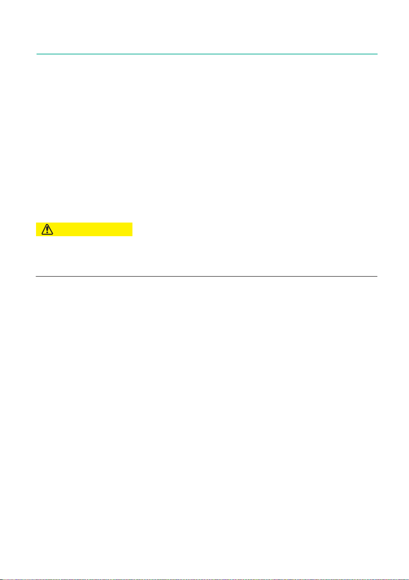
CAUTION This marking warns of a potentially dangerous situa
tion in which failure to comply with safety require
ments could result in slight or moderate physical
injury.
Notice This marking draws your attention to a situation in
which failure to comply with safety requirements
could lead to property damage.
Important
This marking draws your attention to important infor
mation about the product or about handling the prod
uct.
Tip
This marking indicates tips for use or other informa
tion that is useful to you.
Information
This marking draws your attention to information
about the product or about handling the product.
Emphasis
See …
Italics are used to emphasize and highlight text and
identify references to sections of the manual, dia
grams, or external documents and files.
Device -> New Bold text indicates menu items, as well as dialog and
window headings in the program environment. Arrows
between menu items indicate the sequence in which
the menus and sub-menus are opened.
Sample rate Bold text in italics indicates inputs and input fields in
the user interfaces.
uThis symbol indicates an action step.
AD103C
MARKINGS USED
6
2.2 Symbols on the device
CE mark
With the CE mark, the manufacturer guarantees that the product
complies with the requirements of the relevant EC directives (the
Declaration of Conformity can be found on the HBK website
(www.hbm.com) under HBMdoc).
Statutory waste disposal marking
In accordance with national and local environmental protection
and material recovery and recycling regulations, old devices that
can no longer be used must be disposed of separately and not
with normal household garbage.

7
AD103C
SPECIAL FEATURES
3 SPECIAL FEATURES
SSupply voltage 5 VDC ±5 %
STransducer excitation via external power supply.
SMeasurement input ohmic full bridges
SNominal (rated) sensitivity ±2 mV/V
SRS232 serial interfaces
SDigital filtering and scaling of the measurement signal
SCorrection of non-linearity
SPower failsafe storage of parameters
SIndestructible storage of factory defaults
SChoice of measured value output speed (max. 1200 M/s)
SAll settings made via the serial interface
SZero balance (±2 %)
SAutomatic zero tracking (0.5 d/s, ±2 %)
SAutomatic zero on start-up (±2 %...±20 %)
STrigger functions (level pre-/post-triggering, external pre-/post-triggering)
SFour limit switches
SExtreme value memory (MIN/MAX)
SFilling and dosing function
SHardware switch for parameter protection in legal-for-trade (LFT) applications
SDiagnostic bus

AD103C
MECHANICAL CONSTRUCTION
8
4 MECHANICAL CONSTRUCTION
AD amplifier boards are designed as plug-in boards and plug into the carrier board via a
25-pin sub-D connector.
The use of an AED basic device (not supplied with the AD103C) adds the following char
acteristics to extend the functionality:
SMechanical protection (IP65) via AED9101D, AED9201B, AED9301B, AED9401A or
AED9501A basic devices
SOverall bridge resistance (40) 80...4000 Ωvia the power supply to the basic devices
SAdditional interfaces RS232, RS422/RS485, Profibus, CAN bus, DeviceNet
SElectrically isolated digital inputs/outputs
SEMC protection (tested)
SCover for the ‘write protection’ switch and stamping point for LFT applications
SDiagnostic bus
The basic device features terminals for the transducer, power supply and PC connec
tions, switches for interface selection, and the voltage stabilizer. The connection cables
exit the housing via PG glands (see the respective operating manuals, Basic devices):
AED9101D basic device RS232/RS485 2- or 4-wire interface
AED9201B basic device RS232/RS485 4-wire interface
AED9301B basic device Profibus interface
AED9401A basic device CANOpen or DeviceNet interface
AED9501A basic device CANOpen or DeviceNet interface
The basic devices still differ in the following functionality:
AED9101D basic device Supports the input IN1
AED9201B basic device Supports the inputs IN1, IN2 and OUT1...6
AED9301B and AED9401A basic devices
Support the inputs IN1, IN2 and OUT1...4
AED9501A basic device Supports the input IN1
The AED9201B, AED9301B and AED9401A basic devices achieve complete electrical
isolation of the amplifier from the power supply, the serial interface and the digital
inputs/outputs.
All basic devices support the diagnostic bus.
9
AD103C
AMPLIFIER BOARD ELECTRICAL CONFIGURATION
5 AMPLIFIER BOARD ELECTRICAL CONFIGURATION
The digital transducer electronics circuit basically comprises the following function
groups:
SAmplifier
SAnalog/digital converter (A/D)
SEvaluation unit (μP)
SPower failsafe parameter storage (EEPROM)
SRS232 serial interface
SDigital inputs/outputs (HCMOS)
SPower supply
SHardware switch for write protection of LFT parameters
SBus connection for DeviceNet, CANOpen and diagnostic functions
CAUTION
The analog part is supplied with power via the external 5 VDC power supply, which is simul
taneously used as the bridge excitation voltage.
The supply voltage range of 5 VDC +5 % must not be exceeded.
The AED's external supply voltage must have low residual ripple (< 10 mV), as this supply
voltage must simultaneously be used as the bridge excitation voltage.

AD103C
AMPLIFIER BOARD ELECTRICAL CONFIGURATION
10
5.1 Function
RS232
Digital I/O
AED9101D
SG transducer
AD103C
18...30 V
Power supply unit
Voltage
stabilizer
Calibration
Measurement
mode
Zero
RS485
4-wire
EEPROM
Production number
Linearization
Digital filter
Sample rate
Zero setting
Sensitivity
1200…115200 bauds
Computer
RS485
2-wire Diagnostic bus
RS485
2-wire
Fig. 5.1 AED9101D basic device with amplifier board (example)
The analog transducer signal is first amplified, then filtered and converted to a digital
value in the analog/digital converter. The digitized measurement signal is conditioned in
the microprocessor. The conditioned signal is forwarded to a computer via the serial
interface. All the parameters can be stored power failsafe in the EEPROM.
In the factory, the transducer electronics are adjusted by a calibration unit to the absolute
values 0 mV/V and +2 mV/V. From these measured values, the electronics use the com
mands SZA and SFA to determine a factory characteristic curve and map the subsequent
measured values over this curve. The following measured values are delivered, depend
ing on the output format (COF):
Output format Input signal Meas. values for
NOV = 0
Meas. values
for NOV > 0
Status on delivery
NOV = 0
Binary, 2 chars.
(integer)
0...2 mV/V 0 - 20000 digits 0 - NOV
Binary, 4 chars.
(long integer)
0...2 mV/V 0 - 5120000 digits 0 - NOV
ASCII 0...2 mV/V 0 - 1000000 digits 0 - NOV X
The unit of measurement mV/V reflects the ratio of the measuring voltage to the excita
tion voltage at the transducer bridge.
The factory setting for the SZA/SFA curve should not be changed.

11
AD103C
AMPLIFIER BOARD ELECTRICAL CONFIGURATION
With the pair of parameters LDW and LWT, you have the option of adapting the character
istic curve to meet your requirements (scale curve) and to standardize the measured val
ues to the required scaling value (e.g. 3000 d) using the NOV command.
The AD103C also offers you the option of setting different increments (1 d, 2 d, 5 d, 10 d,
20 d, 50 d, 100 d) using the RSN command.
5.2 Signal conditioning
FMD
ASF
Measuring
bridge Filter
Factory
calib-
ration
Sample
rate
Fine flow
Coarse flow
Net
RUN
BREAK
Dosing control
Ready
Alarm
Gross
measured
value
1 Trigger
2 Tare
Linear-
ization
User
scaling
Amplifier
ADC
SZA
SFA
NOV,RSN
LDW
LWT LIC
TAV,TAS
IMD
1...4
LIV
ICR
Limit
values
MIN/
Net
measured
value
MAX
Extreme
values
Fig. 5.2 Signal flow diagram of the AD103C amplifier
After amplification and A/D conversion, the signal is filtered by adjustable digital filters
(FMD, ASF commands). The ASF and FMD commands set the bandwidth for the
measurement signal (digital filters). The ICR command can be used to modify the output
rate (measured values per second), irrespective of the filter bandwidth. The HSM com
mand selects the ADU sample rate (600 Mw/s or 1200 Mw/s).
Various types of digital filter are implemented in the AED and these are selected using
the FMD command. With FMD0, filters are also available below the 1 Hz bandwidth. In the
FMD1 filter mode, fast-settling filters with high damping in the stop band are activated.
The signal conditioning functions described below are executed at the set output rate,
even if there is no communication via the serial interface.
The SZA and SFA commands are used to define the factory characteristic curve.
As a user, you can set your own characteristic curve with the LDW, LWT and NOV com
mands, without changing the working standard calibration (SZA/SFA). You can also
choose between gross/net (TAS, TAR command). The ZSE command activates auto
matic zero on start-up. There is also an automatic zero tracking function (ZTR) and zero
setting function (CDL).

AD103C
AMPLIFIER BOARD ELECTRICAL CONFIGURATION
12
The (LIC) command is available for linearization of the scale curve (with a third order
polynomial). Polynomial parameters can be defined using the HBK PanelX PC software.
The current measured value is read out using the MSV? command. The format of the
measured value (ASCII or binary) is set with the COF command. You can also use the COF
command to select automatic data output.
5.2.1 Triggering
The AD103C features four trigger functions to support functions in packaging machinery
and checkweighers:
SLevel post-/pre-triggering via an adjustable level
SExternal post-/pre-triggering via a digital trigger input (IN1)
Either the gross or the net measured value can be used as the trigger function input
(depending on the tare function, TAS).
This special measurement mode is activated via the TRC command. The established
measured value is read out using the MAV? command.
5.2.2 Limit value outputs
The AD103C provides four limit values, which are set via the LIV command. Limit value
outputs are available as hardware outputs on the 25-pin connector and as logical outputs
in the measured value status. As the input signal for limit value monitoring, you have a
choice between the gross value, the net value, the trigger result or the MIN/MAX extreme
values.
(also see section 5.6.2, Function of limit value outputs and control inputs)
5.2.3 Control inputs
You can activate 2 inputs (IN1/2) as control inputs via the IMD1; command.
A Low/High (0 V →5 V) edge at input IN1 initiates an external triggering process (TRC,
external triggering).
A Low level at input IN2 causes the measured value to be tared. For the tare input, the
Low level must be present for at least 20 ms (debounce time).
You can find more detailed information in the PanelX Help.
The IMD2 command activates the dosing function. This also switches the function of the
two control inputs:
IN1 = Stop (BRK) and IN2 = Start (RUN)
5.2.4 Extreme values
The AED includes an extreme value function, which can monitor either gross or net
measured values or trigger results (MAV). The two extreme values (MIN and MAX) are

13
AD103C
AMPLIFIER BOARD ELECTRICAL CONFIGURATION
output using the PVA command. The CPV command can be used at any time to clear the
extreme values. Activation is achieved via the PVS command.
5.2.5 Filling control
The filling and dosing function is activated via the IMD2; command.
In this case, the limit value function settings and the trigger function for the digital inputs/
outputs are meaningless.
5.2.6 Diagnostic function
A diagnostic function has been integrated in the AD103C to monitor dynamic measure
ments. This function includes a memory for 512 (binary) measured values and associ
ated status information. Different recording modes are available, so that the processes
can be analyzed without interrupting measurement.
The diagnostic function can be accessed in two modes:
SVia the main communication channel (RS232/RS485, Profibus, CAN bus or DeviceNet
SVia the diagnostic bus (RS485 2-wire)
The diagnostic output allows a display to be connected. Here, the measured values are
transmitted in encrypted form.
AD103C
ELECTRICAL CONNECTION
14
6 ELECTRICAL CONNECTION
6.1 Transducer connection
SG transducers with full bridge can be connected.
Bridge resistance RB= 40...4000 Ω(external excitation voltage). SG transducers must
operate at a bridge excitation voltage of 5 VDC.
Transducers with a bridge resistance >1000 Ωcan also be connected in principle. How
ever, this will increase the noise of the measurement signal (increased measurement
ripple).
Currentconsumption +≤90mA )ExcitationvoltageUB
BridgeresistanceRB
Important
Make sure that a low-noise constant voltage source is used for the excitation voltage, as
the quality of the power supply is directly reflected in the measurement result (see Calcula
tion).
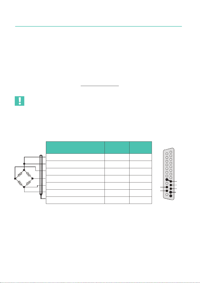
6.1.1 Connection in a 6-wire configuration
HBK color
code
Pin
socket
Bridge excitation voltage (+) bl 9/21
Sense lead (+) gn 10
Measurement signal (+) wh 24
Measurement signal (–) rd 11
Bridge excitation voltage (–) bk 12/13
Sense lead (–) gy 23
Cable shield ye Housing
Fig. 6.1 Transducer connection (6-wire) to the AD103C amplifier board
14 1
gy
wh
25
bl
gn
rd
bk
13
Bu1 amplifier
(back of connector)

15
AD103C
ELECTRICAL CONNECTION
6.1.2 Connection in a 4-wire configuration
Connection without an extension cable; sense lead bridged at the transducer electronics.
HBK color
code
Pin
socket
Bridge excitation voltage (+) bl 9/21
Sense lead (+) gn 10
Measurement signal (+) wh 24
Measurement signal (–) rd 11
Bridge excitation voltage (–) bk 12/13
Sense lead (–) gy 23
Cable shield ye Housing
Fig. 6.2 Transducer connection of supply leads and sense leads in a 4-wire
configuration without a cable extension
Information on the type of connection, cable length and cross-section
Voltage drops that can lower the bridge excitation voltage may occur, depending on the
bridge resistance of the load cell used, and the length and cross-section of the load cell
connection cable. The voltage drop at the connection cable is also dependent on temper
ature (copper resistance). Likewise, the output signal of the load cell changes in propor
tion to the bridge excitation voltage.
This is balanced out when connecting in a 6-wire configuration.
(See operating manuals of AED9101D, AED9201B, AED9301B, AED9401A or AED9501A
basic devices)
Bu1 amplifier
(back of connec
tor)
14 1
bl
wh
25 bk
13
rd
AD103C
ELECTRICAL CONNECTION
16
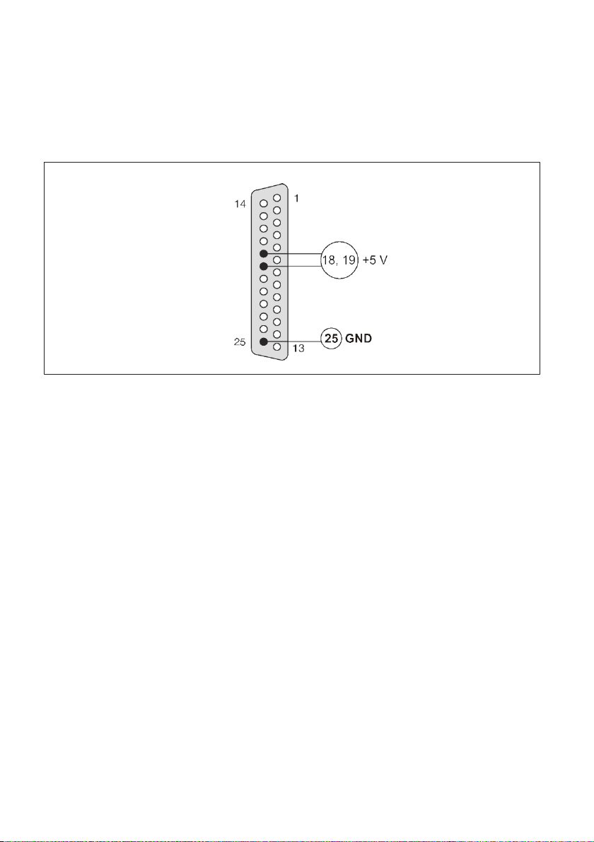
6.2 Connecting the supply voltage
The supply voltage must meet the following requirements:
Regulated DC voltage +5 V ±5 %
Residual ripple <10 mV (peak-to-peak)
AD103C current consumption <120 mA (without SG bridge)
AD103C
Fig. 6.3 Connecting the supply voltage to the amplifier board
17
AD103C
ELECTRICAL CONNECTION
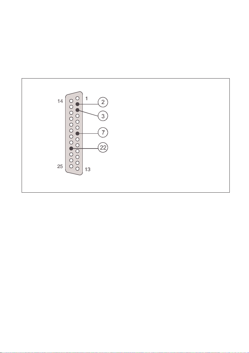
6.3 Connecting the RS232 serial interface
The amplifier board is equipped with an RS232 interface as standard. Baud rates of
1200...115200 bit/s are available for this serial interface. In addition to the RxD (Receive
Data) and TxD (Transmit Data) interface lines, a DTR (Data Terminal Ready) control line is
also available for triggering bus driver modules (e.g. LTC485). When the amplifier board
is installed in a basic device, the RS422 (factory default), RS485 and RS232 interfaces are
directly available.
AD103C amplifier
Bu1
(back of connector)
RxD, RxD < -3 V -> quiescent level
TxD, TxD < -3 V -> quiescent level
GND, interface
DTR, DTR < -3 V -> quiescent level
DTR, DTD > +3 V -> transmitter active
RS232:
Fig. 6.4 Pin assignment for the RS232 interface on the amplifier boards
AD103C
ELECTRICAL CONNECTION
18
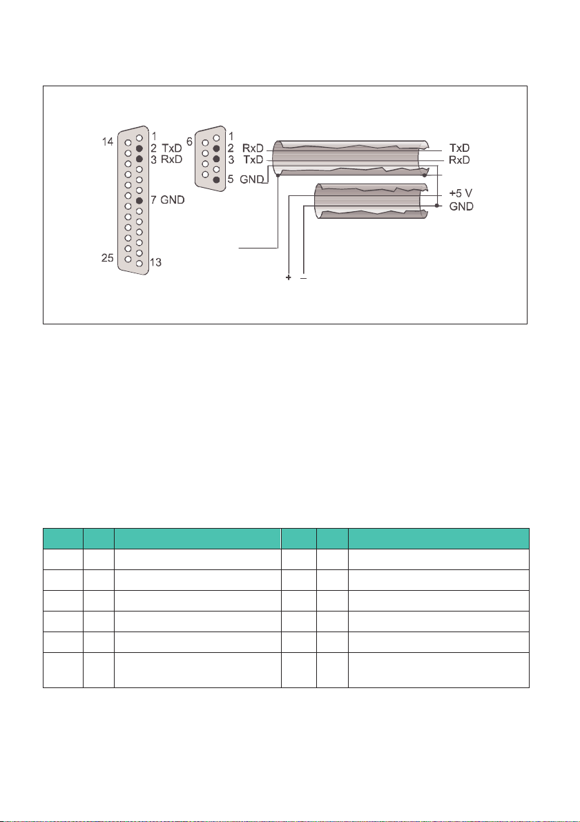
Connecting the AED to a computer via the RS232 interface
Computer
RS232
AD103C
RS232
9-pin socket
(solder view)
Housing
Power supply
unit
25-pin socket
(solder view)
Housing
Fig. 6.5 Connecting the AD103C to a PC or controller via RS232 and supply voltage
(5VDC only!!)
Multi-channel measurement is only possible with appropriate bus drivers (RS485) (see
operating manuals of the AED9101D, AED9201B, AED9301B, AED9401A or AED9501A
basic devices).
6.4 Connecting CAN bus or DeviceNet
The AD103C amplifier has an additional 12-pin connector for providing another connec
tion to the AED basic device. The following signals are directed via this two-row connec
tor:
PIN I/O Signal PIN I/O Signal
1 - GND 2 - Not connected
3 - Not connected 4 I DRxD (diagnosis)
5 I CRxD (CAN/DeviceNet) 6 O CTxD (CAN/DeviceNet)
7 O DDTR (diagnosis) 8 O DTxD (diagnosis)
9 - Not connected 10 - Not connected
11 I CDS (CAN/DeviceNet selec
tion)
12 I DIAG (digital outputs), for HBK
only
I/O – input/output
Table of contents
Languages:
Other HBK Amplifier manuals


