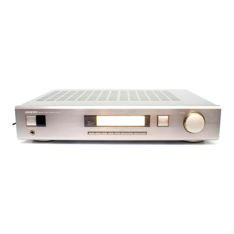
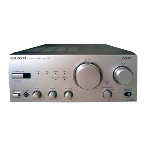
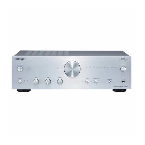
Onkyo TX-820 User manual

Artistry
in
Sound
ONKYO.
TX-820/800
Quartz
Synthesized
Tuner
Amplifier
Quarz-Synthesizer-Empfanger-Verstarker
Ampli-tuner
a
synthétiseur
a
quartz
Sintonizador
de
cvarzo
amplificador
Quartz-Synthesizer-Tuner-Versterker
Quartz
syntestuner/forstarkare
Amplificatore
sintanizzatore/sintetizzato
al
quarzo

e
Congratulations
on
your
purchase
of
the
ONKYO
TX-820,
TX-800
Tuner-Amplifier.
@
Please
read
this
manual
thoroughly
before
making
connections
and
turning
power
on.
®@
Following
the
instructions
in
this
manual
will
enable
you
to
obtain
optimum
performance
and
listening
enjoyment
from
your
new
TX-820,
TX-800.
©
Please
retain
this
manual
for
future
reference.
CONTENTS
Features
Important
safeguards
Precautions
System
connections
Front
panel
facilities
Operations
Using
the
remote
control
transmitter
(TX-820
only)
Troubleshooting
guide
Specifications
“SOON
TWN
=A
=
Features
Pi
ee
Se
me
oe
Ew
en
OP
aed
a
Rea
ng
ae
®@
Plenty
of
clean
Power
TX-820:
40
watts
per
channel
into
8
ohms
with
no
more
than
0.3%
total
harmonic
distortion
(2
x
75
watts
dynamic
power
at
4
ohms)
TX-800:
35
watts
per
channel
into
8
ohms
with
no
more
than
0.3%
total
harmonic
distortion
(2
x
65
watts
dynamic
power
at
4
ohms)
®
Six
Program
Inputs
Including
Video
Sound
with
Logic
Controlled
Feather-Touch
Keys
The
TX-820
and
TX-800
can
both
handle
six
input
sources:
FM,
AM,
phono,
CD
player,
tape-1/video
and
tape-2.
This
gives
you
plenty
of
flexibility
as
well
as
the
chance
to
expand
your
system
in
future.
The
logic
controlled
feather
touch
keys
make
for
smooth
switching
between
sources.
@
APR
(Automatic
Precision
Reception)
System
Onkyo’s
exclusive
APR
system
lets
every
FM
broadcast
sound
its
best.
Its
built-in
electronic
brain
monitors
the
signal
and
selects
the
optimum
settings
for
RF
local/DX
and
stereo
auto/mono.
The
APR
system
settings
are
shown
by
indicators
on
the
front
panel.
@
Multi-Function
Infrared
Remote
Control
Included
(TX-820)
The
included
remote
control
covers
all
of
the
TX-820’s
major
functions
including
volume
up/down,
audio
muting,
tuner
preset
station
frequency
and
input
selector
switching.
{t
can
also
contro!
the
major
functions
of
any
Onkyo
cassette
deck
or
CD
player
bearing
the
fRL_
mark
after
you
make
the
appropriate
connections
with
the
TX-820.
®@®
20-Station
FM/AM
Random
Preset
Tuning
with
Battery-Free
Backup
®
Two
Pairs
of
Speaker
Output
Terminals
Important
safeguards
LTR
AT
a
a
“WARNING”
FOR
POWER
CORDS
WITHOUT
PLUGS
(FOR
“TO
REDUCE
THE
RISK
OF
FIRE
OR
ELECTRIC
SHOCK,
DO
NOT
BRITISH
MODELS)
EXPOSE
THIS
APPLIANCE
TO
RAIN
OR
MOISTURE.”
@
Replacement
and
mounting
of
an
AC
plug
on
the
power
supply
CA
UTION
aN
unit
should
be
performed
only
by
qualified
service
“TO
REDUCE
THE
RISK
OF
ELECTRIC
SHOCK,
DO
NOT
REMOVE
@
IMPORTANT:
The
wires
in
the
mains
lead
are
coloured
in
ac-
COVER
(OR
BACK).
NO
USER-SERVICEABLE
PARTS
!NSIDE.
cordance
with
the
following
code:
REFER
SERVICING
TO
QUALIFIED
SERVICE
PERSONNEL.”
Blue:
Neutral
Brown:
Live
:
As
the
colours
of
the
wires
in
the
mains
lead
of
this
apparatus
may
CAUTION:
10
PREVENT
ELECTRIC
SROCR
DONO
USE
not
correspond
with
the
coloured
markings
identifying
thet
erminals
THIS
(POLARIZED)
PLUG
WITH
AN
EXTENSION
CORD,
RE-
fa
yeliiclug.piaecedice
dalle
CEPTACLE
OR
OTHER
OUTLET
UNLESS
THE
BLADES
CAN
BE
The
wire
which
is
coloured
blue
must
be
connected
to
the
terminal
FULLY
iNSERTED
TO
PREVENT
BLADE
EXPOSURE.
which
is
marked
with
the
letter
N
or
coloured
black.
The
wire
which
is
coloured
brown
must
be
connected
to
the
terminal
which
is
marked
with
the
letter
L
or
coloured
red.
@
For
models
having
power
cord
with
a
polarized
plug.

Observe
the
following
precautions
to
obtain
troublefree
perform-
ance
for
many
years.
1.
Avoid
places
subject
to
direct
sunlight
or
extremely
high
or
low
temperatures.
.
Avoid
damp
or
dusty
places
and
places
directly
affected
by
vibrations
from
the
speakers.
In
particular,
avoid
placing
the
unit
on
or
above
one
of
the
speakers.
.
Avoid
unstable
locations
and
high
places
from
which
the
unit
could
fall.
.
Ventilation
—
The
unit
should
be
situated
so
that
its
location
or
position
does
not
interfere
with
proper
ventilation.
For
ex-
ample,
the
unit
should
not
be
placed
on
a
bed,
sofa,
rug
of
similar
surface
that
could
block
the
ventilation
openings
or
placed
in
a
built-in
installation,
such
as
a
bookcase
or
cabinet,
that
could
impede
the
flow
of
air
through
the
ventilation
openings.
.
Heat
~
The
unit
should
be
situated
away
from
heat
sources
such
as
radiators,
heat
registers,
or
other
appliances
(including
amplifiers)
that
produce
heat.
.
Cleaning
of
the
internal
parts
should
be
performed
only
by
qualified
service
personnel.
.
Spillage
—
Care
should
be
taken
so
that
objects
do
not
fall
and
liquids
are
not
spilled
into
the
enclosure
through
the
openings.
.
Damage
Requiring
Service
—
The
unit
should
be
serviced
by
qualified
service
personne!
when:
A.
The
power
supply
cord
or
the
plug
has
been
damaged;
or
B.
Objects
have
fallen
or
liquid
has
been
spilted
into
the
unit;
or
C.
The
unit
has
been
exposed
to
rain;
or
D.
The
unit
does
not
appear
to
operate
normally
or
exhibits
a
marked
change
in
performance;
or
E.
The
unit
has
been
dropped
or
the
enclosure
damaged.
.
Servicing
—
The
user
should
not
attempt
to
service
the
unit
beyond
that
described
in
the
operating
instructions.
All
other
servicing
should
be
referred
to
qualfied
service
personnel.
This
apparatus
complies
with
requirements
of
EEC
directive
82/499/EEC.
The
tuner
amplifiers
are
provided
with
the
following
remote
control
transmitters:
USA
and
Canadian
models
Other
area
MOdeIS.........
ccc
ceccesceesessseeenseeesesesecessseesses
RC-144S
RC-148S
Precautions
SSS
SSS
ae
en
a
a
ee
ee
a
a
1.
Warranty
Card
The
serial
number
is
written
on
the
rear
pane!
of
this
unit.
Copy
the
serial
number
and
model
number
onto
your
warranty
card
and
keep
it
in
a
safe
place.
.
Recording
Copyright
Recording
of
copyrighted
material
for
other
than
personal
use
is
illegal
without
permission
of
the
copyright
holder.
.
AC
Fuse
The
fuse
is
located
inside
the
chassis
and
is
not
user
serviceable.
lf
power
does
not
come
on,
contact
your
Onkyo
service
center.
.
Care
From
time
to
time
you
should
wipe
off
the
front
and
rear
panels
and
the
cabinet
with
a
soft
cloth.
For
heavier
dirt,
dampen
a
soft
cloth
in
a
weak
solution
of
mild
detergent
and
water,
wring
it
out
dry,
and
wipe
off
the
dirt.
Following
this,
dry
immediately
with
a
clean
cloth.
Do
not
use
rough
material,
thinners,
alcohol
or
other
chemical
solvents
or
cloths
since
these could
damage
the
finish
or
remove
the
panel
lettering.
.
Power
WARNING
BEFORE
TURNING
ON
POWER
FOR
THE
FIRST
TIME,
READ
THE
FOLLOWING
SECTION
CAREFULLY.
Some
models
are
designed
for
use
only
with
the
power
supply
voltage
of
the
region
where
they
are
sold.
European
models
(except
U.K.):
Canadian
models:
U.K.
&
Australian
models:
Worldwide
models:
AC220V,
50Hz
AC120V,
60Hz
AC
240V,
50Hz
120
and
220V
switchable,
50/60Hz
@
Voltage
Selector
(Rear
Panel)
Worldwide
models
are
equipped
with
a
voitage
selector
to
conform
with
local
power
supplies.
Be
sure
to
set
this
switch
to
match
the
voltage
of
the
power
supply
in
your
area
before
turning
the
power
switch
on.
Voltage
is
changed
by
sliding
the
groove
in
the
switch
with
a
screwdriver
to
the
right
or
left.
Confirm
that
the
switch
has
been
moved
all
the
way
to
the
right
or
left
before
turning
the
power
switch
on.
Models
without
a
voltage
selector
can
only
be
used
in
areas
where
the
power
supply
is
the
same
as
that
of
the
unit.
220V
™
at
AC220V
220V
\
120V™
at
AC120V
120V
Tuning
Step
Frequency
Switch
(Bottom)
Worldwide
models
are
equipped
with
a
switch
that
contras
the
AM
(9kHz/10kHz)
and
FM
(50kHz/100kHz)
band
tuningst
eps.
Be
sure
to
set
this
switch
to
match
the
tuning
step
frequen
cy
in
your
area.
U.S.A.
and
Canada
10kHz/100kHz
Other
area
9kHz/50kHz

System
connections
SSS
ae
a
General
Switch
the
main
power
switch
off
before
performing
connections.
Aliso
be
sure
to
perform
left
and
right
channel
connections
properly.
Models
for
some
areas
Do
not
connect
both
indoor
and
are
equipped
with
a
outdoor
FM
antennas.
If
you
decide
to
screw-type
FM
antenna
install
an
outdoor
antenna,
be
sure
to
terminal
(75/300
ohms).
disconnect
the
indoor
feeder
antenna.
Outdoor
AM
antenna
Outdoor
SPEAKER
(A)
Indoor
T-shaped
Am
LOOP
R
L
FM
antenna
antenna
ANTENNA
s
OO
+
-
-
+
“if
TX-820
only
s/f
Worldwide
models
only
490
a
44
oy
44
pe
!
(Wasa
SELECTORS,
‘ioe
‘ee
cae
1
“So
Ben
a
baer
1
H
PHONO
CD
TAPEUMIOEO
U
snrhengfs
Pe
NEES
re
Mort
oh Ts
=,
SOO
RAT
ono
Sy
‘N
\
F
Me
Ground
connection
ts
not
\
AC
POWER
necessary
for
turntable
SUPPLY
CORD
'
without
ground
lead
}
$$$
$$$
let
ald.
‘
I
1
Ld
O
O
'
L L
>)
(@)
L
t
:
Bik
SPEAKER
IMPEDANCE
us
1)
r@l(e
TX-820
:
4
ohms
MIN.
/
speaker
—
=
TX-800
:
8
ohms
MIN.
/
speaker
COMPACT
CASSETTE
TAPE
CASSETTE
TAPE
R
L
PURNTGBCE
DISC
DECK
1
DECK
2
SPEAKER
(8)
PLAYER
or or
GRAPHIC
VIDEO
CASSETTE
EQUALIZER
RECORDER
FM
Antenna
Connections
Use
the
T-shaped
antenna
if
you
live
in
an
area
where
signal
strength
of
FM
broadcasts
is
high.
Connect
the
antenna
to
the
FM
75
ohms
terminals
and
place
the
antenna
on
a
wall
or
other
surface
in
the
position
in
which
reception
is
best.
If
signal
strength
is
low
in
your
area,
use
a
multi-element
FM
outdoor
antenna.
Consult
your
Onkyo
authorized
service
center
about
the
right
type
of
antenna
for
your
area.
Directional
linkage
NOTES:
type
splitter
1.
Do
not
connect
both
the
indoor
T-shaped
antenna
and
an
outdoor
FM
antenna.
If
you
decide
to
install
an
outdoor
antenna,
be
sure
to
disconnect
the
indoor
T-shaped
antenna.
Do
not
use
the
same
antenna
for
both
FM
and
TV
reception
To
receiver
To
TV
(or
VCR)
since
the
FM
and
TV
signals
can
interfere
with
each
other.
tf
you
must
use
a
common
FM/TV
antenna,
use
a
directional
linkage
type
splitter.

AM
Antenna
Connections
An
AM
loop
antenna
is
included
in
the
installation
instructions
bag.
Take
out
the
connection
line
and
connect
it
to
the
AM
antenna
terminals.
This
{oop
antenna
can
be
placed
on
top
of
any
stable
surface
or
attached
to
a
wall.
Try
several
positions
to
determine
which
gives
the
best
reception.
Be
sure
the
antenna
is
not
near
a
speaker,
power
cord,
television
set,
VCR,
or
motorized
appliances.
When
using
an
externa!
AM
antenna,
do
not
remove
the
loop
an-
tenna;
connect
both
antennas
to
the
AM
antenna
terminals.
AM
loop
antenna
assembly
connect
to
the
AM
antenna
terminals.
Remove
the
vinyl
tie
and
take
out
the
connection
ni
Bend
in
the
reverse
line.
direction.
a.
With
the
antenna
on
top
of
any
stable
surface
b.
With
the
antenna
attached
to
a
wall
Installation
hole
Mount
on
a
wall,
etc.
NOTE:
AM
reception
is
easily
affected
by
television
sets
and
VCRs.
Therefore,
AM
reception
may
be
poor
if
this
unit
is
placed
too
close
to
aTV
or
a
VCR.
Speaker
Connections
(SPEAKERS)
1.
Connect
the
speakers
to
A
and/or
B
terminals.
2.
When
connecting
speakers,
proper
polarity
is
important.
Always
connect
the
(+)
terminal
(red)
on
this
equipment
to
the
(+)
terminal
on
the
speaker
and
the
(—)
terminal
(black)
on
this
equipment
to
the
(—)
terminal
on
the
speaker.
3.
Do
not
connect
a
single
speaker
in
parallel
to
the
right
and
left
channel
outputs.
4.
Use
speaker
cables
that
have
a
low
impedance
and
that
are
as
short
as
possible.
«
Attach
speaker
cables
to
the
rear
panel
speaker
terminals
with
care,
being
sure
that
connections
are
made
firmly
and
that
there
is
no
possibility
of
a
short
circuit
occurring.
NOTE:
When
both
the
A
and
B
Speaker
Selector
switches
are
depressed,
the
A
and
B
speaker
systems
operate
in
a
series
connection.
If
only
one
pair
of
speakers
is
connected,
no
sound
at
all
will
be
heard.
(TX-820
only)
Connections
for
Remote
Control
(REMOTE
CONTROL)
A
cassette
tape
deck
and
compact
disc
player
that
have
the
Onkyo
fRI
mark
can
be
operated,
using
the
accessory
remote
control
transmitter.
(
f2]
:
Remote
Interactive)
TX-820
Ri
Disc
PLAYER
nEMOTE
CONTROL
Ri
CASSETTE
REMOTE
TAPE
DECK
CONTROL
An
fQ
|
remote
control
cable
equipped
with
a
0.136”
(3.5mm)
diameter
miniature
two-conductor
phone
plug
is
attached
to
the
TX-820
and
to
any
compact
disc
player,
with
the
«Q}
mark.
To
use
an
Onkyo
compact
disc
player
and
cassette
tape
deck with
the
FRI
mark,
insert
the
accessory
remote
control
cable
plug
into
the
REMOTE
CONTROL
jacks.
As
far
as
connecting
sequence
is
concerned,
it
doesn't
matter
whether
the
cable
is
connected
from
the
TX-820
to
the
cassette
tape
deck
or
to
the
compact
disc
player.
The
remote
control
transmitter
is
operated
by
facing
it
towards
the
remote
control
sensor
of
the
TX-820.
NOTE:
Remote
control
operation
is
not
possible
when
only
the
remote
control
cable
is
connected.
Remote
control
cable
and
pin
cord
must
be
connected.
Conadian
models
only
If
you
own
a
Canadian
model
of
the
TX-820,
the
Onkyo
turntable
can
be
operated,
using
the
accessory
remote
control
transmitter.
@
if
your
turntable
has
an
fRI
mark
on
it,
insert
the
accessory
fR1_
remote
contro!
cable
plug
attached
to
the
Onkyo
turntable
with
the
fRI
mark
into
the
PHONO
of
the
TX-820’s
REMOTE
CONTROL.
REMOTE
CONTROL
TURNTABLE
TX-820
@
Onkyo
turntables
that
can
be
remote
controlled
but
do
nothave
the
(QI
mark.
This
equipment
has
a
7-pin
DIN
jack
on
the
rear
panel.
Connect
this
jack
and
the
jack
on
the
rear
of
the
Tx-820
with
the
special
cable
for
this
purpose,
which
is
sold
separat
ely.
TURNTABLE
as
For
this
special
cable
contact
an
Onkyo
Sewsce
Center.
For
a
turntable
(3.5
mm
pin
to
7-pi
n
plug
cable)
part
number
:
20104
40

Turntable
Connections
(PHONO)
Connect
the
output
leads
of
the
turntable
to
the
PHONO
jacks.
Be
sure
to
connect
the
ground
(earth)
jead
wire
from
the
turntable
to
the
ground
terminal
(GND)
(Antenna
terminal).
Lack
of
proper
ground
connection
will
cause
hum.
Turntables
not
provided
with
GND
wires
do
not
need
to
be
connected.
1.
Place
the
turntable
on
a
firm
shelf
or
deck
free
from
vibrations
(especially
those
generated
by
the
speaker
system).
If
the
turntable
is
permitted
to
pick
up
such
unwanted
vibrations,
not
only
with
the
performance
of
the
unit
drop,
but
distortion
in
the
bass
frequencies
and
howling
in
the
speakers
may
also
occur.
Check
the
turntable
instruction
manual
for
any
other
precautions.
The
loud
noises
that
occur
when
connecting
and
disconnecting
the
turntable
leads,
replacing
the
cartridge
or
lowering
the
tonearm
could
damage
the
speakers.
Always
turn
the
power
switch
off
before
making
connections.
.
If
an
Onkyo
turntable
with
remote
contro!
jack
is
used
with
this
unit,
the
remote
control
transmitter
can
also
be
used
to
start
and
stop
turntable
operation.
In
this
case,
the
turntable
and
TX-820
must
be
connected
with
a
remote
control
cord.
Insert
the
plug
into
the
PHONO
jack
of
the
REMOTE
CONTROL
on
the
rear
panel
of
the
TX-820.
(Please
refer
to
“Connections
for
Remote
Control
on
page
4.)
(USA
and
Canadian
models
only)
Compact
Disc
Player
or
Other
Component
Connections
(CD)
Connect
the
output
leads
of
the
CD
player
or
an
additional
audio
component
to
the
CD
jacks.
An
Onkyo
CD
player
with
remote
contro!
that
has
the
(QI
mark
can
be
operated
by
the
TX-820.
(Please
refer
Tape
Deck
and
Graphic
Equalizer
Connections
(TAPE-1,
TAPE-2)
Ve
This
unit
has
facilities
for
two
tape
decks.
!f
you
are
using
only
one
tape
deck,
connect
it
to
the
TAPE-1/VIDEO
jacks.
If
you
have
two
tape
decks,
connect
one
to
the
TAPE-1/VIDEO
jacks
and
the
other
to
the
TAPE-2
jacks.
Connect
the
output
leads
of
the
tape
decks
to
the
TAPE-1/VIDEO
and
TAPE-2
“PLAY”
jacks.
Connect
the
input
leads
of
the
tape
decks
to
the
TAPE-1/VIDEO
and
TAPE-2
“REC”
jacks
of
the
unit.
For
more
details,
refer
to
your
tape
deck
instruction
manual.
To
connect
a
graphic
equalizer,
too,
use
the
TAPE-2
jacks
and
connect
the
second
tape
deck
to
the
tape
jacks
of
the
equalizer.
To
connect
a
graphic
equalizer
and
second
tape
deck
to
the
TAPE-2
jacks.
To
TAPE-2
“REC”
jacks
of
TX-820/800
To
TAPE-2
“PLAY”
jacks
of
TX-820/800
EQUALIZER
Graphic
equalizer
REC
PLAY
Second
tape
deck
If
you
have
an
Onkyo
tape
deck
with
the
FRI
remote
control
jack,
connect
it
to
the
TAPE-1/VIDEO
jacks.
Please
refer
to
the
section
“Connections
for
Remote
Control”
(page
4)
tegarding
.
For
the
audio
signal
of
a
VDP,
VCR,
etc.,
make
the
connections
to
the
TAPE-1/VIDEO
“PLAY”,
“REC”
jacks.
For
details,
refer
to
the
operating
instructions
of
the
video
equipment
concerned.
to
“Connections
for
Remote
Control”
on
page
4.)
For
more
details,
4.
refer
to
your
CD
player
instruction
manual.
connection
of
the
remote
control
cable.
(TX-820
only)
5
Front
panel
facilities
m
{i
I
1
1
i
ni
ON:
©
quartz
syNTHESIZED
TUMER
AMPLIFIER
FRE
2
SS
a)
|
cw
wocounee
oN
a
==
|
=
—
ues
PHONES.
ep
Spe
wenoe
LEE
i
L
I
maim
=
a
fr
L—€)
TO
LOY
ick
1
PowER
TiMOor
MEMORY
INPUT
SELFCIOR
=
bie
Tape
MNTOR
|
TaPt-1DK0
PHONE
<
OMe
OF
NOTE:
@
The
features,
specifications,
and
display
for
the
TX-820
and
TX-800
are
slightly
different.
Read
this
manual
carefully
to
Operate
the
model
you
have
purchased
correctly.
(STEREO)
FM
MODE
r—TUNHD—
AUDIO
Hunan
ey
BUTT
MUTE
TAPE-2
MONITOR

ame
INPUT
SELECTOR
TAPE.
TUNER
=
PHONO
cp
cases
0
PRESET
>
yd
t
TUNER
a
crete
DECK-A
DEGK-8
‘m
f
Pa
a
—=
——
-_
20
* °
om
a
eu
s
f
}
E
as
<4
= ~ =
||
avoio
__[
0)
i
F
MUTING
al
-_
A
UP
2t
Vouwume
a
YOOwN
2
a
~<
Cod
RC-148S/144S
(TX-820
only)
Power
Switch
(POWER)
Press
once
to
turn
power
on
and
once
again
to
turn
power
off.
Tape
Monitor
Button
(TAPE-2
MONITOR)
and
Indicator
Press
this
button
to
use
the
tape
deck
connected
to
the
TAPE-2
PLAY/REC
jacks
for
recording,
playback
or
dubbing.
The
on
the
display
lights
up.
Note
that
dubbing
can
only
be
performed
from
tape
deck
1
to
tape
deck
2.
If
tape
deck
2
is
a
3-head
model,
the
just-recorded
signal
can
be
monitored
as
a
recording
is
being
made.
The
button
is
also
enabled
by
the
key
on
the
remote
control
transmitter.
(TX-820
only)
Input
Selector
Buttons
and
Indicators
The
button
pressed
is
shown
in
Display
[3].
For
FM
or
AM,
the
band
and
the
frequency
are
shown
in
Display
[13].
®
Audio
Selectors
TAPE-1/VIDEQ:
Press
to
listen
to
the
TAPE-1
or
VIDEO
AM:
Press
to
listen
to
an
AM
broadcast
FM:
Press
to
listen
to
an
FM
broadcast
PHONO:
Press
to
listen
to
the
turntable
CD:
Press
to
listen
to
the
CD
player
The
button
is
also
enabled
by
the
key
on
the
remote
control
transmitter
(TX-820
only).
FM
Mode
Button
(FM
MODE)
and
Indicator
When
the
mode
button
is
set
to
AUTO,
the
indicator
lights
and
FM
stereo
reception
is
possible.
When
the
FM
stereo
station
reception
is
weak
and
noisy,
press
the
mode
button
and
the
indicator
goes
out,
resulting
in
noise-free
monaural
reception.
At
this
point,
the
indicator
goes
out.
(Mode
operation
is
effective
for
FM
reception
only).
Bass
Control
Knob
(BASS)
Adjust
to
strengthen
or
weaken
bass
response.
Treble
Control
Knob
(TREBLE)
Adjust
to
strengthen
or
weaken
treble
response.
Balance
Control
Knob
(BALANCE)
Use
this
control
to
adjust
the
relative
volume
levels
of
the
left
and
right
speaker
systems.
Volume
Control
Knob
(VOLUME)
Turn
clockwise
to
increase
the
volume
level.
The
volume
can
be
adjusted
manually
and
by
the
remote
contro!
transmitter’s
Volume
UP/DOWN
key
[24].
(TX-820
only)
Loudness
Control
Switch
(LOUDNESS)
When
listening
at
low
volume
levels,
depress
this
switch
to
boost
the
very
high
and
very
low
frequencies
to
provide
a
more
natural
sound.
Memory
Button
(MEMORY)
and
Indicator
Press
this
button
to
place
a
station
in
the
memory
using
the
FM/AM
Preset
buttons
.
When
this
button
is
pressed,
the
indicator
lights
for
about
8
seconds.
While
the
indicator
is
lit,
press
one
of
the
FM/AM
Preset
buttons
[12].
Upon
press,
the
displayed
frequency
will
be
stored
in
memory.
The
pressed
preset
number
will
be
displayed
in
digital
form,
and
the
memory
indicator
will
go
out
to
indicate
that
memory
operation
has
been
completed.
Shift
Button
(SHIFT)
and
Indicators
The
FM/AM
Preset
buttons
can
be
used
to
store
a
total
of
20
radio
stations.
Use
this
button
to
switch
the
Preset
buttons
between
the
memory
channel
1-10
mode
and
the
memory
channel
11-20
made.
The
setting
switches
between
1-10
and
11-20
each
time
this
button
is
pressed
and
the
respective
in-
dicator
lights.
When
power
is
turned
on,
the
setting
is
the
same
as
when
power
was
last
turned
off.
FM/AM
Preset
Buttons
(PRESET
STATION)
and
Display
Use
these
buttons
to
recall
an
FM
or
AM
station
or
to
store
a
station
in
the
memory.
When
a
button
is
pressed,
the
corre-
sponding
preset
number
is
displayed
in
digital
form. Refer
to
the
Memory
section
for
details.
Tuning
Selector
Buttons
(4
DOWN,
UP
Pp)
DOWN:
Press
to
tune
in
a
lower
frequency.
UP:
Press
to
tune
in
a
higher
frequency.
When
listening
to
a
broadcast,
pressing
the
UP
button
will
increase
the
FM
or
AM
reception
frequency.
Pressing
the
DOWN
button
decreases
the
frequencies
(Manual
Tuning).
lf
the
button
is
pressed
for
longer
than
0.5
seconds
in
AM
or
FM,
and
then
released,
broadcast
frequencies
will
change
automatically
until
a
station
is
tuned
in
(Auto
Tuning).
When
either
the
upper
or
the
lower
end
of
the
frequency
range
is
reached,
the
displayed
frequency
will
automatically
switch
back
to
the
other
end
of
the
range
and
continue
to
either
in-
crease
or
decrease
as
before.
For
example,
when
the
DOWN
tuning
selector
is
pressed,
the
frequency
will
decrease
until
the
lowest
frequency
is
reached.
The
displayed
frequency
will
then
switch
back
to
the
highest
frequency
and
continue
de-
creasing
as
before.
APR
Indicators
Automatic
Precision
Reception
System
(FM
Mode)
APR
system
is
Onkyo’s
unique
computer-controlled
system.
APR
system
automatically
sets
the
RF
stage
gain
(Distance/
Local),
stereo/mono
reception
modes
to
the
proper
settings
for
the
qualily
of
the
broadcast
currently
being
received.
This
indicator
changes
each
time
the
APR
circuit
switches
between
the
LOCAL/DX
or
AUTO/MONO
to
show
the
current
APR
setting.
(APR
system
is
effective
for
only
FM
reception.)
NOTE:
@
When
FM
Mode
button
[4]
is
not
AUTO,
the
APR
Made
selection
function
does
not
operate,
and
the
MODE
indicator
is
forced
to
“MONO”.
The
“MONO”
display
lights
up
for
FM
monaural
reception.
The
RF
MODE
will
indicate
LOCAL
when
sufficient
signal
is
received.
Remote
Control
Sensor
(REMOTE
SENSOR)
(TX-820
only)
This
sensor
receives
the
remote
control
signals.
Speaker
Selector
Switches
(SPEAKERS)
This
unit
can
drive
two
pairs
of
speakers
in
pairs
(A
or
B)
or
fours
(A
+
B).
To
listen
to
both
speaker
systems
at
once,
dep
ress
both
speaker
selector
switches.
Headphone
jack
(PHONES)
Stereo
headphones
with
a
standard
binaural
plug
can
be
connected
here.

[18
Stereo
Indicator
(STEREO)
This
lights
when
an
FM
stereo
broadcast
is
received
and
does
not
light
when
a
mono
broadcast
is
received.
It
will
not
light
up
when
an
FM
stereo
broadcast
is
received
if
the
signal
is
weak,
since
reception
will
automatically
switch
to
the
monaural
mode.
This
indicator
lights
only
during
FM
stereo
reception.
13
Tuned
Indicators
(TUNED)
These
indicators
light
up
when
an
FM
or
AM
broadcast
is
being
received
properly.
The
“
|
”
indicator
blinks
during
scanning.
When
a
station
is
tuned
in,
this
blinking
stops
and
both
”
¥”
and
“
‘thik!
”
indicators
light
up.
These
indicators
do
not
fight
for
weak
broadcasts.
@
Remote
Control
Transmitter
Controls
RC-148S/144S
(TX-820
only)
20
Tape
Operation
Keys
(DECK-A,
DECK-B)
These
keys
control
Onkyo
double
cassette
tape
decks
that
can
be
remote
controlled.
Use
the
DECK-B
keys
to
control
single
cassette
tape
decks
with
the
FRI
mark.
@/it
:
When
this
is
pressed,
the
recording
stand-by
mode
is
entered.
<=:
The
tape
plays,
moving
from
right
to
left,
or,
in
the
re-
cording
stand-by
mode,
recording
begins.
@
=
:tnterrupts
all
operations.
>
:The
tape
plays,
moving
from
left
to
right,
or,
in
the
re-
cording
stand-by
mode,
recording
begins.
“4:
Fast
forward
from
right
to
left.
>>
>
Fast
forward
from
left
to
right.
For
connections,
please
refer
to
the
section
“Connections
for
Remote
Control.”
Consult
your
Onkyo
service
center
for
further
details.
20
cp
Operation
Keys
(CD)
These
keys
are
used
to
operate
an
ONKYO
CD
player
with
the
fl
mark.
>»
:Press
this
key
to
play
the
CD
player.
i!
—:
Press
this
key
to
pause
the
CD
play
back.
To
resume
disc
play,
press
the
PLAY
key.
™@
=:
Press
this
key
to
stop
the
CD
player.
I44:
Press
this
key
to
go
back
to
the
beginning
of
the
current
track
and
again
to
skip
back
to
the
previous
track.
>i
:
Press
this
key
to
skip
to
the
next
track.
Refer
to
the
CD
player
instruction
manual
for
additional
in-
formation.
For
connections,
please
see
the
section
on
“Connections
for
Remote
Control.”
Consult
your
Onkyo
service
center
for
further
details.
223
Tuner
Operation
Keys
(
<«
PRESET
P
)
When
the
UP
(
»
)
or
DOWN
(
€
)
remote
this
key
is
pressed,
the
next
higher
or
ijower
memory
channel
is
recalled.
Each
time
UP
or
DOWN
key
is
pressed,
the
following
memory
channel
in
the
corresponding
direction
is
recalled.
If
the
key
is
held
down
the
memory
channel
will
increase
or
decrease
contin-
uously
until
key
is
released.
23
Audio
Muting
Key
(AUDIO
MUTING)
and
Indicator
This
key
temporarily
switches
off
the
sound
from
the
speaker
or
headphone.
Pressing
this
key
will
operate
the
TX-820's
audio
muting
circuit.
The
audio
muting
indicator
;|AUDIO
MUTE]
will
light.
Pressing
the
key
again
will
turn
off
the
audio
muting.
24
Volume
Keys
(
4
uP,
1
DOWN)
These
keys
have
the
same
function
as
that
of
the
volume
control
[8].
The
volume
level
can
be
adjusted
by
pressing
the
UP
or
DOWN
key,
with
the
volume
control
knob
rotating
si-
multaneously.
Canadian
models
only
(RC-144S)
@
Phono
Operation
Key
(PLAY/REJECT)
This
key
is
used
to
operate
the
turntable.
The
phono
operation
key
can
be
used
only
when
the
PHONO
input
selector
button
has
been
pressed.
Each
time
the
phono
operation
key
is
Pressed,
the
remote
control
transmitter
alternately
emits
the
play
or
reject
command.
Refer
to
the
turntable
instruction
manual
for
additional
instructions
on
operating
the
turntable.
For
connections,
please
refer
to
the
section
“Connections
for
Remote
Control.”
Consult
your
Onkyo
service
center
for
furher
details.
NOTE:
Before
starting
record
play
using
remote
control,
confirm
that
there
is
a
record
on
the
platter.
!f
there
is
no
record,
the
stylus
will
be
lowered
to
the
platter,
resulting
in
serious
damage
to
the
stylus.
@
CD
Operation
Key
(DISC)
Press
to
use
for
sequential
selection
of
discs
in
the
order
they
were
loaded
on
the
CD
changer.
Operations
a
eae
ee
EE
Tuner
Reception
1.
Confirm
that
the
TAPE-2
MONITOR
indicator
[2]
is
off,
audio
muting
(TX-820
only)
is
off,
and
press
the
FM
or
AM
Input
Selector
button
[3].
2.
To
tune
in
an
FM
or
AM
station
not
stored
in
the
memory,
press
one
of
the
Tuning
selector
buttons
[13].
If
you
press
UP,
the
frequency
is
increased.
Pressing
DOWN
decreases.
Note
that
the
frequency
is
changed
in
50
(100)
kHz
steps
in
FM
and
9
(10)
kHz
steps
in
AM
when
the
Tuning
selector
buttonis
pressed
in
single
steps.
If
this
button
is
pressed
continuously
for
more
than
0.5
seconds,
the
auto
tuning
mode
is
entered,
and
fre-
quencies
are
scanned
automatically.
When
a
broadcast
signal
is
received,
scanning
stops
and
that
frequency
is
displayed.
If
a
different
frequency
is
desired,
press
the
button
once
again.
@
Scanning
will
not
stop
for
weak
broadcasts.
To
receive
a
weak
FM
broadcast,
select
the
frequency
of
the
desired
broadcast
station.
3.
To
recall
a
station
stored
in
the
memory,
simply
press
the
Preset
station
button
corresponding
to
the
desired
station.
Be
sure
to
set
the
Shift
button
[17]}to
the
range
(1-10
0r
11-20)
for
the
memory
channel
to
be
recalled.
This
is
arandom
FM/AM
memory.
If
a
preset
station
button
is
pressed
when
the
input
selector
is
not
set
to
FM
or
AM,
the
input
is
automatically
switched
to
FM
or
AM.
4.
The
Tuned
indicators
[19]
will
light
if
the
broadcast
is
being
properly
received.
These
indicators
do
not
light
for
weak
broadcasts.
The
red
”
”
indicator
blinks
during
scanning.
5.
The
Stereo
indicator
will
light
up
if
the
broadcast
is
being
received
in
stereo.
The
Stereo
indicator
wil!
not
light
up
if
the
broadcast
is
monaural
or
too
weak
to
be
received
in
Stereo.
Memory
Function
This
unit
can
store
a
total
of
20
FM
and
AM
stations
in
the
memory
for
instant
recall
at
any
time
without
using
the
Tuning
selector
buttons.
The
20
stations
can
be
any
combination
of
FMand
AM
broadcasts.
Read
the
following
directions
carefully
to
avoid
mis-
taken
operations.
1.
Select
the
FM
or
AM
to
be
placed
in
the
memory
usingt
he
Input
Selector
button
[3].
Confirm
the
TAPE-2
MONITORi
ndicator
is
off
and
Audio
muting
(TX-820
only)
is
off.
2.
Use
the
shift
button
to
set
the
1-10
or
11-20
range,
depending
on
which
memory
channel
is
to
be
used.
3.
Tune
in
the
broadcast
to
be
placed
in
the
memory
using
the
Tuning
selector
buttons.
4.
Press
the
Memory
button
and,
while
the
Memory
indicator
re-
mains
lit
(about
8
seconds),
press
one
of
the
FM/AM
Preset
buttons.
5.
When
the
Preset
button
is
pressed,
the
Memory
indicefor
will
go
out
and
the
pressed
preset
number
will
come
on.
The
fre-
quency
currently
shown
in
the
frequency
display
is
now
stored
in
the
memory.
6.
If
the
Memory
indicator
goes
out
before
you
have
pres
sed
one
of
the
Preset
buttons,
simply
press
the
Memory
button
[i
O]again
to
give
yourself
another
8
seconds.
7.
Placing
another
broadcast
in
the
same
memory
channe
|
auto-
matically
cancels
the
station
previously
stored
in
that
c
hannel,
—7J-

NOTES:
Preset
frequencies
can
be
transferred
to
other
channels.
For
example,
the
FM
station
stored
on
Preset
button
number
6
can
be
transferred
to
Preset
button
number
1
in
the
following
manner:
1)
Press
Preset
button
number
6.
2)
Press
the
Memory
button
(Memory
indicator
lights).
3)
Press
Preset
button
number
1.
4)
The
same
station
is
now
stored
on
both
Preset
buttons
1
and
6.
Memory
Preservation
This
unit
does
not
require
memory
preservation
batteries.
A
built-in
memory
power
back-up
system
preserves
the
contents
of
the
memory
during
power
failures
and
even
when
the
unit
is
unplugged.
The
unit
must
be
plugged
in
and
the
power
switch
turned
on
and
off
once
in
order
to
charge
the
back-up
system.
Note
thatsince
this
is
not
a
permanent
memory,
the
power
switch
must
be
turned
on
and
off
a
few
times
each
month
to
keep
the
back-up
system
operative.
The
memory
preservation
period
after
power
has
been
turned
off
varies
depending
on
climate
and
placement
of
the
unit.
On
the
average,
memory
contents
are
protected
over
a
period
of
a
few
weeks
after
the
last
time
power
has
been
turned
off.
This
period
is
shorter
when
the
unit
is
exposed
to
a
highly
humid
climate.
Using
the
Phonograph
Record
1.
Press
the
PHONO
Input
Selector
button
[3],
and
confirm
that
the
TAPE-2
MONITOR
indicator
is
off
and
audio
muting
(TX-820
only)
is
off.
2.
Follow
the
turntable
operating
instructions.
NOTE:
Confirm
that
the
turntable
is
connected
to
the
PHONO
input
jacks
on
the
rear
panel.
Using
the
Compact
Disc
Player
1.
Press
the
CD
Input
Selector
button
[3],
and
confirm
that
the
TAPE-2
MONITOR
indicator
is
off.
2.
Follow
the
operating
instructions
for
the
CD
player.
NOTE:
Confirm
that
the
CD
player
is
connected
to
the
CD
input
jacks
on
the
rear
panel.
Tape
Playback
1.
Press
the
TAPE-1/VIDEO
Input
Selector
button
[3]
or
TAPE-2
MONITOR
button
[2]
depending
on
which
pair
of
TAPE PLAY
jacks
the
deck
is
connected
to.
2.
For
playback,
follow
the
operating
instructions
of
the
tape
deck
or
video
equipment.
NOTE:
Confirm
that
the
output
leads
from
the
tape
deck
to
the
TAPE-1/VIDEO
and/or
TAPE-2
jacks
on
the
rear
panel.
Tape
Recording
1.
Make
all
connections
between
the
tape
deck
and
the
unit
as
shown
in
the
System
Connections
Diagram.
2.
Radio:
Press
the
FM
or
AM
Input
Selector
button
[3].
Record:
Press
the
PHONO
Input
Selector
button
[3].
CD:
Press
the
CD
input
Selector
button
[3].
3.
Put
the
tape
deck
in
the
recording
mode.
The
recording
can
be
monitored
through
the
speakers
or
headphones
as
desired.
For
TAPE-2,
turn
on
the
corresponding
Tape
Monitor
button
to
hear
the
signal
that,
having
been
recorded,
is
returned
from
the
deck
to
the
TX-820/800.
(if
the
deck
has
three
heads).
4.
Set
the
proper
recording
level
using
the
controls
on
the
tape
deck
used
for
recording.
Also,
during
recording
and
dubbing
Operations,
never
change
the
positions
of
any
controls
(bass,
treble,
etc.)
on
this
unit.
Tape-to-Tape
Dubbing
1.
Connect
the
two
tape
decks
to
this
unit
as
shown
in
the
System
Connections
diagram.
2.
Load
the
original
tape
in
tape
deck
1
and
the
blank
tape
in
tape
deck
2.
3.
Press
the
TAPE-1/VIDEO
Input
Selector
button
[3].
4.
Put
tape
deck
1
in
the
playback
mode
and
tape
deck
2
in
the
recording
mode.
5.
The
source
signal
can
be
monitored
through
the
speakers
or
headphones,
when
the
TAPE-2
MONITOR
button
is
in
the
OFF
position.
If
tape
deck
2
has
three
heads,
the
just-recorded
signal
can
be
monitored
(when
the
TAPE-2
MONITOR
button
is
in
the
ON
position).
Refer
to
the
tape
deck
instruction
manuals
for
more
details.
Using
the
Graphic
Equalizer
1.
Connect
the
graphic
equalizer
to
the
TAPE-2
jacks
on
the
rear
panel.
2.
If
a
second
tape
deck
is
used,
connect
it
to
the
tape
jacks
on
the
graphic
equalizer.
.
Press
the
TAPE-2
MONITOR
button
[2].
.
Follow
the
graphic
equalizer
operating
instructions.
5.
To
record
an
equalized
signal,
use
tape
deck
2
(connected
to
the
equalizer)
for
recording.
Bw
Direct
function
feature
(TX-820
only)
NOTE:
This
function
works
when
an
Onkyo
cassette
tape
deck
or
CD
player
with
the
{QI
mark
is
connected
to
a
TX-820
withan
fRI
remote
contro!
cable.
Just
by
directly
operating
the
desired
component
(compact
disc
player,
or
tape
deck),
the
TX-820’s
input
selector
automatically
switches
to
that
component.
The
component
that
was
being
used
stops,
and
the
desired
component
starts
operation.
Therefore,
it
is
not
necessary
to
switch
the
TX-820’s
input
selector
when
changing
listening
sources.
Another
way
to
switch
listening
sources
is
to
press
the
TX-820’'s
input
selector
of
the
desired
fistening
source.
The
current
listening
source
will
then
stop
automatically
and
the
desired
listening
source
wil]
start
operation.
Example
1
When
the
compact
disc
player's
play
button
is
pressed,
the
TX-8
20's
input
selector
will
switch
automatically
to
“CD.”
If
the
current
lis-
tening
source
was
a
tape
deck,
tape
playback
will
stop
and
the
compact
disc
player
will
start
playing.
Example
2
With
a
tape
deck
as
the
current
listening
source,
if
the
TX-820's
input
selector
is
switched
to
“CD,”
the
tape
deck
will
stop
playing
and
the
compact
disc
player
will
start
playing.
NOTES:
@
The
direct
function
feature
does
not
apply
to
turntable.
@
Insome
cases,
the
direct
function
may
not
work
the
first
time
the
input
selector
is
pressed.
Pressing
the
input
selector
again
will
enable
the
direct
function.
(This
is
to
prevent
irregular
unit
operation.)
El

Using
the
remote
control
transmitter
(TX-820
only)
SS
a
For
details
on
the
function
of
each
control,
see
the
description
in
“Remote
Control
Transmitter
Controls
(RC-148S/144S)
on
page
7.
Batteries
The
remote
control
transmitter
is
powered
by
two
batteries.
Before
using
this
unit
for
the
first
time,
insert
the
two
batteries
(included)
as
shown
in
the
diagram.
The
remote
control
trans-
mitter
has
no
on/off
switch.
Average
battery
life
is
one
year.
This
period
may
be
shorter
depending
on
the
frequency
of
use
and
environment
(temperature
and
humidity)
in
which
the
re-
mote
control
transmitter
is
used.
If
the
remote
control
transmitter
does
not
operate
even
though
front
panel
controls
function
normally,
the
batteries
should
be
replaced.
Use
only
batteries
listed
in
the
following
chart.
.
Do
not
leave
an
expired
battery
in
the
case
as
it
may
leak
or
damage
the
battery
case.
.
When
inserting
the
batteries,
be
sure
the
(+)
and
(—):
ends
are
properly
aligned.
.
Do
not
use
nickel-cadmium
(rechargeable)
batteries.
.
Do
not
use
one
specified
(manganese)
battery
and
one
al-
kaline
battery
at
the
same
time.
.
Replace
both
batteries
at
once;
do
not
use
one
old
and
one
new
battery
together.
Transmitter
Battery
Replacement
®
_
Remote
sensor
5m
(16
feet)
Remote
contro}
transmitter
RC-148S/144S
Precautions
.
Remove
the
batteries
if
the
remote
control
transmitter
is
not
going
to
be
used
for
a
long
time.
The
batteries
of
the
remote
control
transmitter
must
be
replaced
periodically.
Remember,
however,
that
commands
will
be
re-
ceived
only
when
the
power
switch
of
the
TX-820
is
on.
This
unit
uses
infrared
rays.
Therefore,
commands
may
not
be
received
properly
if
the
front
panel
of
the
TX-820
is
exposed
to
bright
light.
To
prevent
this
from
occurring,
place
the
TX-820
so
that
it
is
not
directly
exposed
to
a
bright
light.
If
the
TX-820
is
placed
inside
an
audio
rack
behind
a
glass
door,
the
door
should
not
use
colored
glass
or
have
any
decorations
on
it
since
this
could
shorten
the
range
or
prevent
commands
from
being
received.
Use
of
other
infrared
remote
control
devices
in
the
same
room
may
cause
interference.
The
transmitter
operates
up
to
a
distance
of
about
five
meters
(16
feet).
the
transmitting
window
must
always
be
pointed
at
the
reception
window
when
a
command
is
sent
to
the
TX-820.
If
this
remote
control
transmitter
does
not
operate
properly,
confirm
that
the
batteries
are
not
dead.
If
the
problem
persists,
contact
your
Onkyo
service
center.

Trouble
shooting
guide
[SSS
aaa
ae
a
a
ane
a
Ee
NOTE
(TX-820
only):
‘lf
a
problem
occurs,
first
operate
the
unit
using
the
front
panel
controls
to
confirm
that
it
is
not
due
to
a
malfunction
(or
worn
out
batteries)
of
the
remote
control
transmitter.
Trouble
No
power.
@
Power
cord
is
disconnected.
@
Connect
power
cord.
®@
AC
fuse
blown.
®
Contact
Onkyo
Service
Center.
Power
but
no
sound.
®@
Tape
monitor
switch
on.
®@
Switch
to
off.
®
Audio
muting
switch
on.(TX-820
only)
|
@
Switch
to
off
by
remote
contro!
transmitter.
®
Bad
connections.
®
Check
input
leads,
speaker
leads,
pin
plugs,
etc.
®@
Amplifier
protection
circuitry
has
been
|@
Contact
Onkyo
Service
Center.
activated.
Hum,
low
frequency
noise.
@
Poor
or
no
input
ground.
®
Check
outer
conductor
of
input
plugs.
®
Poor
or
no
phono
motor
ground.
®
Check
for
proper
ground
connection.
Howling
when
the
volume
is
turned
up.
|
@
Turntable
and
speakers
are
too
close
®
Move
them
farther
apart.
together.
Rough
or
scratchy
sound.
High
range
is
|
®
Stylus
of
pick-up
is
worn.
@
Replace.
not
clear.
®
Stylus
tip
is
dirty.
@
Clean.
@
Treble
control
too
high.
®
Turn
treble
contro!
down.
AM
stations
cannot
be
received.
@
AM
!oop
antenna
is
not
attached.
®
Connect
the
included
AM
loop
antenna
to
the
AM
antenna
terminals.
Buzzing
noise
on
AM
(particularly
con-
|
@
Noise
from
electrical
apparatus
such
as
|@
Move
AM
loop
antenna
to
different
position.
spicuous
at
night
or
with
weak
stations).
|
fluorescent
lamp.
®
Set
up
outdoor
AM
antenna.
High
pitched
noise
or
buzzing
noise
on
|
@
Noise
from
TV.
®
Place
the
AM
loop
antenna
as
far
as
possible
from
TV.
the
TV.
@
Move
unit
away
from
TV
set.
Crackling
noise
on
AM
and
FM.
®@
Noise
caused
by
turning
fluorescent
@
Move
antenna
as
far
as
possible
from
the
fiuores-
lamp
on
and
off.
cent
lamp.
®@
Noise
from
automobile
ignition.
@
Install
and
FM
outdoor
antenna
as
far
as
possible
from
the
road.
®@
Change
the
position
or
direction
of
the
outdoor
antenna.
FM
tuned
and
stereo
indicators
light
but
|
@
Station
is
too
strong.
®
Change
to
T-shaped
antenna.
sound
is
distorted
and
stereo
separation
|
@
Multiple
reflection
of
the
radio
waves
{|
@
Use
antenna
which
has
better
directivity
andselect
is
bad.
because
of
tall
buildings
or
mountains.
a
point
where
the
distortion
is
least.
FM
tuned
and
stereo
indicators
flicker
®
Station
is
too
weak.
®@
Install
an
outdoor
FM
antenna.
on
and
off
and
hiss
is
heard
on
FM.
®
Stereophonic
FM
broadcasts
cover
only
|
@
Change
the
position
or
direction
of
the
outdoor
about
half
the
distance
of
an
ordinary
antenna.
broadcasts.
No
station
is
recalled
when
a
FM/AM
®@
The
power
switch
has
not
been
turned
|®
The
memory
contents
are
lost
if
the
power
switch
is
not
turned
on
a
few
times
each
month.
Store
all
stations
again
and
remember
to
turn
the
power
on
a
few
times
each
month.
on
for
a
long
time
or
the
power
cord
has
been
unplugged
for
a
!ong
time.
preset
button
is
pressed.
@
insert
batteries.
®@
Replace
batteries.
®@
No
batteries
in
remote
control
transmit-
ter.
®
Batteries
have
worn
out.
Front
panel
controls
function
but
remote
control
transmitter
does
not.
(TX-820
only)
The
tuning
steps
by
which
the
tuned
frequency
changes
on
each
band
have
been
set
at
the
factory
to
the
proper
value
for
the
country
where
each
unit
isto
be
sold.
If
you
use
the
unit
in
a
country
where
a
different
tuning
step
is
required
or
if
the
broadcast
frequencies
in
your
cocantry
change
so
that
you
can
not
tune
in
radio
stations
precisely,
take
this
unit
to
an
authorized
Onkyo
Service
Center.

Specification
AMPLIFIER
SECTION
Power
Output:
Musical
Power
Output:
Continuous
Power
Output:
Total
Harmonic
Distortion:
{M
Distortion:
Damping
Factor:
Frequency
Response:
RIAA
Deviation:
Sensitivity
and
Impedance:
Phono
Overload:
Signal-to-Noise
Ratio:
Tone
Controls:
Muting:
TUNER
SECTION
FM:
Tuning
Range:
Usable
Sensitivity:
50dB
Quieting
Sensitivity:
Capture
Ratio:
Image
Rejection
Ratio:
IF
Rejection
Ratio:
Signal
-to-Noise
Ratio:
Selectivity
AM
Suppression
Ratio:
Harmonic
Distortion:
Frequency
Response:
Stereo
Separation:
AM:
Tuning
Range:
Usable
Sensitivity:
Image
Rejection
Ratio:
IF
Rejection
Ratio:
Signal
-to-Noise
Ratio:
Harmonic
Distortion:
GENERAL
Power
Supply:
Dimensions
(W
x
H
x
D):
Weight:
TX-820
40
watts
per
channel,
min.
RMS,
at
8
ohms,
both
channels
driven,
from
40Hz
to
20kHz,
with
no
more
than
0.3%
THD.
2
x
95
watts
at
4
ohms,
1kHz
(DIN)
2
x
68
watts
at
8
ohms,
1kHz
(DIN)
2
x
50
watts
at
4
ohms,
1kHz
(DIN)
2
x
45
watts
at
8
ohms,
TkHz
(DIN)
0.3%
at
rated
power
0.1%
at
30
watt
output
0.3%
at
rated
power
0.1%
at
30
watt
output
35
at
8
ohms
20
-
30,000
Hz
+
1dB
20
—
20,000
Hz
+
0.8dB
Phono:
2.5mV/50
kohms
CD/Tape
Play:
150mV/50
kohms
Tape
Rec:
150mV/3.5
kohms
120mV
RMS
at
1kHz,
0.3%
THD
Phono:
85dB
(at
10mV
input,
A
weighted)
75dB
(IHF
A-202)
CD/Tape:
95dB
(A
weighted)
80dB
(JHF
A-202)
Bass:
+
10dB
at
100Hz
Treble:
+
10dB
at
10kHz
a.
OS
87.5
-
108.0MHz
(50kHz
steps)
Mono:
12.4dBf,
1.2HV,
75
ohms
1.2nV
(S/N
26dB,
40kHz
Devi.)
75
ohms
DIN
Stereo:
19.2dBf,
2.5uV,
75
ohms
25pV
(S/N
46dB,
40kHz
Devi.)
75
ohms
DIN
Mono:
18.2dBf,
2.2uV,
75
ohms
Stereo:
38.2dBf,
22uV,
75
ohms
1.5dB
85dB
90dB8
Mono:
70dB
Stereo:
65dB
50dB
DIN
(+300kHz,
40kHz
dev.)
50dB
Mono:
0.15%
Stereo:
0.30%
30
-
15,000Hz
+
1.5dB
40dB
at
1kHz
30dB
at
100
-
10,000Hz
522
-
1611kHz
(9kHz
steps)
30nV
40dB
40dB
40dB
0.8%
European
models:
AC220V,
50Hz
Canadian
models:
AC120V,
60Hz
U.K&
Australian
models:
AC
240V,
50Hz
Worldwide
models:
120
and
220V
switchable,
50/60Hz
435
x
115
x
320
mm
17-1/8"
x
4-1/2”
x
12-9/16"
6.7
kg.,
14.8
ibs.
Remote
control
transmitter
RC-148S/RC-144S
Transmitter:
Signal
range:
Power
supply:
Infrared
Approx.
5
meters
(16ft.
4”)
Two
“AA”
batteries
(1.5V
x
2)
TX-800
35
watts
per
channel,
min.
RMS,
at
8
ohms,
both
channels
driven,
from
40Hz
to
20kHz,
with
no
more
than
0.3%
THD.
2
x
85
watts
at
4
ohms,
1kHz
(DIN)
2
x
65
watts
at
8
ohms,
1kHz
(DIN)
2
x
45
watts
at
4
ohms,
1kHz
(DIN)
2
x
40
watts
at
8
ohms,
1kHz
(DIN)
0.3%
at
rated
power
0.1%
at
25
watt
output
0.3%
at
rated
power
0.1%
at
25
watt
ouput
35
at
8
ohms
20
-
30,000
Hz
+
1dB
20
—
20,000
Hz
+
0.8dB
Phono:
2.5mV/50
kohms
CD/Tape
Play:
150mV/50
kohms
Tape
Rec:
150mV/3.5
kohms
120mV
RMS
at
1kHz,
0.3%
THD
Phono:
85dB
(at
10mV
input,
A
weighted}
75dB
(IHF
A-202)
CD/Tape:
95dB
(A
weighted)
80dB
(IHF
A-202)
Bass:
+
10dB
at
100Hz
Treble:
+
10dB
at
10kHz
87.5
-
108.0MHz
(50kHz
steps)
Mono:
12.4dBf,
1.2uV,
75
ohms
1.2nV
(S/N
26dB,
40kHz
Devi.)
75
ohms
DIN
Stereo:
19.2dBf,
2.5uV,
75
ohms
25uV(S/N
46dB,
40kHz
Devi.)
75
ohms
DIN
Mono:
18.2dBf,
2.2uV,
75
ohms
Stereo:
38.2dBf,
22V,
75
ohms
1.5dB
85dB
90dB
Mono:
70dB
Stereo:
65dB8
50dB
DIN
(+300kHz,
40kHz
dev.)
50dB
Mono:
0.15%
Stereo:
0.30%
30
—
15,000Hz
+
1.5dB
40dB
at
1kHz
30dB
at
100
-
10,000Hz
522
~
1611kHz
(9kHz
steps)
30LV
40dB
40dB
40dB
0.8%
European
models:
AC220V,
50Hz
Canadian
models:
ACi120V,
60Hz
U.K&
Australian
models:
AC
240V,
50Hz
Worldwide
models:
120
and
220V
switchable,
5(//G0Hz
435
x
115
x
320
mm
17-1/8"
x
4-1/2"
x
12-9/16"
5.7
kg.,
12.6
Ibs.
Specifications
and
features
are
subject
to
change
Witio
alt
notice.

e
val
erzlichen
Gluckwunsch
zum
Kauf
des
Empfangers
TX-820,
TX-800
von
ONKYO.
©
Bitte
lesen
Sie
sich
diese
Bedienungsanleitung
vor
dem
AnschlieBen
und
der
Inbetriebnahme
dieses
Gerats
durch.
@
Wenn
Sie
sich
an
die
in
dieser
Anleitung
erwahnten
Tips
halten,
werden
Sie
schnell
in
der
Lage
sein,
die
Qualitat
des
TX-820,
TX-800
voll
auszukosten.
@
Bitte
heben
Sie
diese
Bedienungsanleitung
auf,
da
Sie
sie
vielleicht
noch
einmal
brauchen.
Eigenschaften
Aufstellung
und
Wartungen
VorsichtsmaBnahmen
Anschlu&diagramm
Bedienungselemente
...
Bedienung
Verwendung
des
Fernbedienungsteils
(nur
fur
den
TX-820)
Betriebsprobleme
und
deren
Behebung
Technische
Daten
Eigenschaften
EE
eR
a
ee
Se
a
ae
®
Reichlich
saubere
Leistung
INHALT
TX-820:
40
W
pro
Kanal!
an
8
Ohm
mit
weniger
als
0,3%
Klirrfaktor
(2
x
75
W
Dynamic
bei
4
Ohm)
TX-800:
35
W
pro
Kanal
an
8
Ohm
mit
weniger
als
0,3%
Klirrfaktor
(2
x
65
W
Dynamic
bei
4
Ohm).
®
Sechs
Programmeingange
einschlieRlich
Videoton
mit
Tipptasten
mit
Logiksteuerung
Sowohl
TX-820
als
auch
TX-800
sind
auf
sechs
Eingangsquellen
ausgelegt:
FM,
AM,
Phono,
CD-Player,
Tape-1/Video
und
Tape-2.
Dadurch
wird
viel
Flexibilitat
garantiert,
ebenso
wie
Erweiterungsmdglichkeit
der
Anlage
in
der
Zukunft.
Die
Tipptasten
mit
Logiksteuerung
ermdglichen
glattes
Umschalten
zwischen
Tonquellen.
@
APR
(automatischer
Prazisionsempfang)
System
Das
von
Onkyo
entwickelte
APR-System
gibt
jede
UKW-Sendung
in
bester
Qualitat
wieder.
Der
eingebaute
Mikrorechner
Uberwacht
Uberwacht
das
Sendesignal
und
wahit
die
optimale
Einstellung
fur
RF
local/DX
und
Stereo
auto/mono.
Die
Einstellungen
des
APR-Systems
werden
durch
die
Anzeigen
an
der
Vorderseite
angezeigt.
@
Mitgeliefertes
Multifunktions-Fernbedienungsteil
(TX-820)
Das
mitgelieferte
Fernbedienungsteil
enthalt
alle
Hauptfunktionen
des
TX-820,
einschlieBlich
Lautstarke
hoher/niedriger,
Audiodampfung,
Tuner-Festsenderfrequenz
und
Eingangsquellenwahl.
Es
kann
auch
die
Hauptfunktionen
jedes
Onkyo-Cassettendecks
oder
CD-Players
mit
der
Markierung
(|
steuern,
wenn
die
Verbindung
zum
TX-820
hergestelit
ist.
@
Speicherung
von
20
UKW/MW
Festsendern
ohne
Batterie
®
Zwei
Paare
von
Lautsprecherausgangen
Aufstellung
und
Wartungen
SSS
LE
ae
ey
VORSICHT:
“DAS
GEHAUSE
NIEMALS
OFFNEN.
SIE
KONNTEN
SONST
EINEN
SCHLAG
BEKOMMEN.
NICHTS
DARF
VOM
BENUTZER
GEWARTET
ODER
REPARIERT
WERDEN.
UBERLASSEN
SIE
WARTUNGSARBEITEN
DEM
QUALIFIZIERTEN
KUNDENDIENST.”
Um
eine
stérungsfreien
Betrieb
sicherzustellen,
die
fol-
genden
Vorsichtsma&nahmen
beachten:
1.
Staub
und
UbermaRige
Feuchtigkeit,
direkte
Sonnenbestrahlung
sowie
Ubermakig
hohe
und
niedrige
Temperaturen
vermeiden.
2.
Daraufachten,
da&
keine
Erschitterungen
auf
das
Gerat
Ubertragen
werden.
Diesen
Baustein
daher
niemals
auf
einer
Lautsprecherbox
abstellen.
3.
Das
Gerat
immer
auf
einer
stabilen
und
waagerechten
Unterlage
abstelien.
4.
Auf
ausreichende
Beltftung
achten.
Das
Gerat
daher
nicht
auf
weichen
Unterlagen
(Teppich,
Kissen
usw.)
aufstellen
und
die
BelUftungsschlitze
nicht
abdecken
(z.B.
bei
Regaleinbau),
da
anderenfatls
die
im
Geradteinneren
erzeugte
Warme
nicht
ab-
gefUhrt
werden
kann.
5.
Die
Nahe
von
Heizkorpern
und
elektrischen
Geraten
mit
st
arker
Warmeentwicklung
vermeiden.
6.
Innenteile
dirfen
nur
von
einem
qualifizierten
Wartungstech-
niker
eingestellt
bzw.
gereinigt
werden.
7.
Darauf
achten,
da&
durch
die
Beliiftungsschlitze
keine
Ge-
genstande
eindringen
und
keine
Flussigkeiten
auf
das
Gerat
verschuttet
werden.
8.
In
den
folgenden
Fallen
den
Baustein
von
einem
qualifizierten
Wartungstechniker
uberprifen
lassen:
A.
Wenn
das
Netzkabel
oder
der
Netzschalter
beschadigt
ist.
B.
Wenn
Gegenstande
oder
Flussigkeiten
in
das
Gerat
ein
ge-
drungen
sind.
C.
Wenn
das
Gerat
UbermaRiger
Feuchtigkeit
ausgesetzt
wurde.
D.
Wenn
Betriebsstérungen
bzw.
anormale
Betriebsbedin—
gungen
festgestellt
werden.
E.
Wenn
das
Gerat
fallengelassen
bzw.
das
Gehause
beschadigt
wurde.
9.
Nicht
in
dieser
Bedienungsanleitung
aufgeftihrte
Wartungsar-
beiten
durfen
vom
Benutzer
nicht
selbst
ausgeftihrt
werden.
Falls
solche
Wartungsarbeiten
erforderlich
werden
sollten
,
wenden
Sie
sich
bitte
an
einen
qualifizierten
Wartungstec
hni-
ker.
@
Das
Gerat
entspricht
den
Bestimmungen
der
EG-
Richtlinie
82/499/EWG.

VorsichtsmaBnahmen
fe
aoe
tk
Oe
er
ee
a
ee
SS
ee
1.
Garantieschein
Die
Seriennummer
dieses
Geradtes
finden
Sie
an
der
Gerate-
ruckseite.
Tragen
Sie
diese
zusammen
mit
der
Modelinummer
in
die
Garantiekarte
ein.
Die
Garantiekarte
an
einem
sicheren
Ort
verwahren.
Urheberrecht
Die
Aufnahme
von
urheberrechtlich
geschiitztem
Tonmaterial
flr
andere
Zwecke
als
private
Verwendung
ist
ohne
Zustimmung
des
Urheberrechtsinhabers
nicht
statthaft.
.
Netzsicherung
Die
Sicherung
liegt
im
Jnneren
des
Gerats
und
soll
nicht
vom
Anwender
ausgewechselt
werden.
Wenn
sich
das
Gerat
nicht
einschalten
la&t,
den
Onkyo-Fachhandler
benachrichtigen.
.
Pflege
In
regelmaRigen
Abstanden
soliten
Front-
und
Ruckplatte
sowie
Gehause
mit
einem
weichen
Lappen
abgewischt
werden.
Hartnackiger
Schmutz
kann
mit
einem
in
milder
Seifenlésung
angefeuchteten
und
gut
ausgewrungenen
Lappen
abgewischt
werden.
AnschlieRend
mit
einem
sauberen
Lappen
trocken-
wischen.
Keine
scheuernden
Stoffe,
Verdinner,
Alkohol
oder
andere
chemische
Lésungsmittel
verwenden,
da
diese
die
Gehauseoberflache
angreifen
und
die
Beschriftung
entfernen
kOnnen.
.
Spannung
WARNUNG
LESEN
SIE
SICH
DIESEN
ABSCHNITT
DURCH,
BEVOR
SIE
DAS
GERAT
ZUM
ERSTEN
MAL
EINSCHALTEN.
AnschluBdiagramm
In
manchen
Landern
ist
Niemals
sowoh!
die
AuBen-als
auch
der
UKW-Antennenanschlu&
die
2
immerantenne
auschlieBen.
Wenn
(75/300
Q)
mit
einer
Sie
eine
AuRenantenne
verwenden,
Schraube
ausgestattet.
mu&
die
Zimmerantenne
abgetrennt
werden.
MW-AuBenantenne
T-fomige
Zimmerantenne
UKW-AuBenantenne
MW-Rahmenantenne
Le
=—<—_—=>
@
Manche
Modelle
kénnen
nur
mit
der
Spannung
des
Gebiets
betrieben
werden,
in
dem
sie
vertrieben
werden.
Europaisches
Model!
auBer
fir
GroRbritannien:
220V,
50
Hz
Kanada:
120V,
60
Hz
Gro&britannien
und
Australien:
240V,
50
Hz
Universalausflhrung:
120/220V
umschaltbar,
50/60
Hz
Spannungswahler
(Riickseite)
Die
Universalausfithrung
dieses
Modells
ist
mit
einem
Spannungswahler
ausgertistet.
Dieser
Spannungswahler
wird
werksseitig
vor
dem
Versand
auf
220
V
eingestellt.
Vor
der
Inbetriebnahme
die
Einstellung
Uberprifen
und
ggf.
korrigieren.
Dazu
den
Spannungswéahler
mit
einem
Schraubenzieher
bis
zum
Anschlag
nach
links
oder
rechts
in
die
entsprechende
Position
schieben,
Ausfiihrungen
ohne
Spannungswahler
kénnen
nur
mit
der
auf
der
Geratertickseite
angegebenen
Spannung
betrieben
werden.
220V
%™
120V
~
Eingestelit
auf
AC
220V
220V
120V™
Eingestelit
auf
AC
120V
@
Frequenzschrittschalter
(Gerateboden)
Alle
Modelle
sind
mit
einem
Schalter
zur
Regelung
der
Frequenzschritte
des
MW-
(9
kKHZ/10
kHz)
und
UKW-Empfangsbereichs
(50
kHz/100
kHz)
ausgestattet.
Bitte
darauf
achten,
da&
dieser
Schalter
den
lokalen
Frequenzintervallen
entsprechend
eingestellt
ist.
USA
und
Kanada
10
kHz/100
kHz
Fir
alle
anderen
lander
9
kHz/50
kHz
Allgemeine
Hinweise
Vor
der
Ausfiihrung
irgendwelcher
Systemanschlisse
zuerst
das
Gerat
Uber
den
Netzschalter
ausschalten.
Ebenso
darauf
achten,
den
linken
und
rechten
Kanal
beim
AnschlieRen
nicht
zu
vertauschen.
LAUTSPRECHER
(A)
R
L
.
O
O
=
+
4,
Nur
fur
den
,
‘sf
TX-820
Nur
auf
dem
Universalmodell
of
oy
‘of
rae
i
CAUTION
ee
SATTIgN
|
|
i
N
ie
'
t
rm
SAKE!
{
J
REMOTE
k
b
!
i
PHONO
CD
TApEVIDEO
wet
‘ey
CONTROL
3]
1
sachs
L
Cee
Oo
ay
oo
19
Of
AAPA
BEP.
|
5
I
las’
we
fe
TN
a
:
ono
NX
%
x
Plattenspieler
ohne
~\
Erdleitung
brauchen
nicht
\
NETCRAGED
geerdet
zu
werden
:
EN
1
+
-
~
+
{
i]
©
O
i
& L L
C)
LAUTSPRECHERIMPEDANZ
R
R
r@)
seas
2S
awd
TX-820
:
Mindestens
4Q
pro
Box
TX-800
:
Mindestens
89
pro
Box
CD-SPIELER
CASSETTENRECORDER
2
R
PLATTENSPIELER
oder
GRAFISCHER
EGUALIZER
LAUTSPRECHER
(B)
CASSETTENRECORDER
1
oder
VIDEORECORDER

UKW-AntennenanschluR
Die
T-Antennen
verwenden,
wenn
Sie
in
einem
Gebiet
wohnen,
wo
starke
UKW-Signale
vorhanden
sind.
Die
Antenne
an
die
Buchsen
FM
75
Ohm
anschlieBen
und
die
Antenne
an
einer
Wand
oder
einer
anderen
Flache
in
einer
Stellung
anbringen,
wo
guter
Empfang
erzielt
wird.
Wenn
in
|hrem
Wohngebiet
die
UKW-Signale
schwach
sind,
eine
Multielement-Auenantenne
verwenden.
Las-
sen
Sie
sich
vom
Onkyo-Fachhandler
tber
den
besten
Antennentyp
fur
thr
Wohngebiet
beraten.
HINWEISE:
1.
Nicht
sowohl
die
T-furmige
Innenantenne
und
eine
UKW-
AuBenantenne
anschlieBen.
Wenn
eine
AuRenantenne
an-
geschlossen
werden
soll,
die
T-firmige
Innenantenne
ab-
trennen.
.
Fur
UKW-
und
Fersehempfang
nicht
dieselbe
Antenne
ver-
wenden,
da
sonst
Interferenzprobleme
auftreten
konnen.
Sollten
Sie
auf
eine
UKW/TV
gemeinsame
Antenne
ange-
wiesen
sein,
einen
geeigneten
Verteiler
(Fachhandel)
ver-
wenden,
Verteiler
mit
Richtwirkung
Zum
Fernseher
oder
Zum
Receiver
Videorecorder
MW-Antennenanschlu&
Eine
MW-Schleifenantenne
ist
mitgeliefert.
Das
Anschlu&kabel
aus
der
Verpackung
entnehmen
und
an
die
MW-
Antennenklemmen
anschlieRen.
Diese
Schleifenantenne
kann
oben
auf
dem
Gerat
aufgestellt
werden
oder
an
einer
Wand
oder
anderen
Flache
an-
gebracht
werden.
Beim
Anbringen
verschiedene
Positionen
aus-
probieren,
um
besten
Empfange
zu
erzielen.
Darauf
achten,
die
Antenne
nicht
in
der
Nahe
von
Lautsprechern,
Stromkabeln,
Fernsehern,
Videorecordern
oder
Elektromotoren
zu
plazieren.
Bei
Verwendung
einer
externen
MW-Antenne
nicht
die
Schle-
ifenantenne
abtrennen;
beide
Antennen
an
die
Antennenklemmen
anschlieRen.
Zusammenbau
der
MW-Rahmenantenne
An
die
AM-Anschiusse
anschlie@en.
B)
Nach
hinten
biegen.
Das
Halteband
entfernen
und
das
AnschluRkabel
entnehmen.
Aufstellen
der
Rahmenantenne
auf
einer
stabile
Oberflache.
Einsetzen
Anbringen
der
Antenne
an
der
Wand.
Bohrioch,
um
an
der
Wand
festzuschrauben
usw.
HINWEIS:
Da
der
MW-Empfang
durch
Fernseher
und
Videorecorder
beintrachtigt
werden
kann,
diese
Gerdte
vom
Empfangsteil
entfernt
aufstellen.
pp
lea
iacitaiiontne
(SPEAKERS)
Die
Boxen
an
die
Klemmen
A
und/oder
B
anschlieBen.
Beim
AnschlieBen
der
Lautsprecherboxen
ist
auf
richtige
Polung
zu
achten:
Den
roten
Piuspol
(+)
des
Verstarkers
mit
dem
Pluspol
(+)
des
Lautsprechers
verbinden;
ebenso
den
schwarzen
Mi-
nuspol
(—)
des
Verstarkers
mit
Minus
(—)
des
Lautsprechers.
Bei
gleichzeitigem
Betrieb
von
zwei
Boxenpaaren
(A+B)
sind
die
Paare
in
Serie
geschafltet.
Falls
beide
Tasten
des
Lautspre-
cher-Wahischalters
eingerastet
werden,
wahrend
nur
ein
Boxenpaar
angeschlossen
ist,
bleibt
die
Anlage
daher
stumm.
3
Niemals
eine
Box
sowohl
an
den
rechten
als
auch
an
den
linken
Kanal
anschlieBen.
4.
Lautsprecherkabel
mit
mdglichst
geringer
Impedanz
verwenden
und
kurz
halten.
+
Lautsprecherkabel
sorgfaltig
anschlie&en,
damit
keine
Kurz-
schliisse
auftreten
kOnnen.
HINWEISE:
Wenn
die
Lautsprechertasten
A
und
B
gleichzeitig
gedritckt
werden,
sind
die
Boxenpaare
A
und
B
in
Serie
geschaltet.
Wenn
in
diesem
Fall
nur
ein
Paar
Boxen
angeschlossen
ist,
kommt
kein
Ton.
(Nur
fiir
den
TX-820)
Anschlisse
fir die
Fernbedienung
(REMOTE
CONTROL)
Ein,
Cassettendeck
und
CD-Player
mit
der
Markierung
fQ1
kann
mit
dem
mitgelieferten
Fernbedienungssender
betrieben
werden.
(
RI
:
Interaktive
Fernbedienung)
RI
REMOTE
CONTROL
RI
cD-
REMOTE
SRIEEEN
CONTROL
AI
CASSETTEN-
REMOTE
DECK
CONTROL
Ein
(1
Fernbedienungskabe!
mit
einem
Miniphonostecker
(3,5
mm)
kann
zur
Verbindung
des
TX-820
mit
jedem
CD-
Player
mit
der
(4
-Markierung
verwendet
werden.
Zur
Verwendung
eines
Onkyo
CD-Players
oder
eines
Cassettendecks
mit
der
FRI
-Markierung
den
Stecker
der
mitcge-
lieferten
Fernbedienung
in
die
Buchsen
REMOTE
CONTROLein-
stecken.
Es
spielt
keine
Rolle,
ob
das
Kabel
zuerst
vom
TX-820
waerst
am
Cassettendeck
oder
CD-Player
eingesteckt
wird.
Der
Sender
der
Fernbedienung
wird
betrieben,
indem
er
auf
den
Fernbedienungssensor
am
TX-820
gerichtet
wird.
HINWEIS:
Fernbedienung
ist
nicht
méglich,
wenn
nur
das
Fernbedie-
nungskabel
angeschlossen
ist.
Es
muB
sowohl!
das
Fernbedie-
nungskabel
als
auch
das
Stiftsteckerkabel
angeschlossen
seirt.

Plattenspieleranschliisse
(PHONO)
2.
Die
Ausgangs-/Eingangskabel
an
die
TAPE
1/VIDEO
und
TAPE
Die
Ausgangskabel
des
Plattenspielers
an
die
PHONO-Buchsen
2
“PLAY”-Buchsen
anschlie&en.
Naheres
entnehmen
Sie
bitte
anschlieBen.
Dabei
darauf
achten,
das
Erdungskabel
vom
Platten-
den
Bedienungsanleitungen
der
Cassettendecks.
spieler
an
Masse
(GND)
(AntennenKlemme)
anzuschlieBen.
Un-
3.
Um
zusatzlich
einen
Graphic
Equalizer
anzuschlieBen,
diesen
sachgema&e
Erdung
verursacht
Leitungsbrummen.
Bei
Platten-
mit
den
TAPE-2
Buchsen
verbinden
und
das
zweite
Deck
an
spielern
ohne
GND-Kabel
ist
dieser
Anschlu&
nicht
nétig.
die
TAPE-Buchsen
des
Graphic
Equalizer
anschlieRen.
{.
Den
Plattenspieler
auf
eine
feste
Unterlage
stellen,
an
denen
er
keinen
Erschiitterungen
(inbesondere
Vibrationen
von
den
AnschlieBen
eines
Graphic
Equalizer
und
eines
zweiten
Lautsprecherboxen)
ausgesetzt
ist.
Die
Einwirkung
solcher
Cassettendecks
an
die
TAPE-2-Buchse.
Vibrationen
mindert
nicht
nur
die
Leistung
des
Plattenspielers,
sondern
verursacht
auch
eine
Verzerrung
der
Ba&frequenzen
Zu
den
TAPE-2
“REC”
Buchsen
des
TX-820/800
und
ruft
méglicherweise
ein
Heulen
der
Lautsprecher
hervor.
Zu
den
TAPE-2
“PLAY”
Buchsen
des
TX-820/800
2.
Weitere
Vorsichtsmaregeln
in
der
Bedienungsanleitung
des
Plattenspielers
bitte
ebenfalls
beachten.
3.
Beim
AnschlieRen
und
Trennen
der
PlattenspieleranschluRkabel,
Austauschen
des
Tonabnehmersystems
oder
Senken
des
Ton-
arms
auftretende,
laute
Stérgerdusche
kénnen
zu
einer
Be-
A
Graphischer
Equalizer
schadigung
der
Lautsprecher
filhren.
Vor
dem
AnschlieRen
deshalb
stets
das
Gerat
Uber
den
Netzschalter
ausschalten.
Anschlisse
fiir
CD-Player
oder
sonstige
Komponenten
(CD)
Die
Ausgangskabel
des
CD-Players
oder
eines
zusatzlichen
Audiobausteins
an
die
CD-Buchsen
anschlieRen.
Fernsteuerbare
REC
PLAY
ewe
Onkyo-CD-Player
mit
dem
RI
-Symbol
konnen
Uber
den
TX-820
4.
Handelt
es
sich
bei
dem
Onkyo-Cassettendeck
um
ein
Modell
betrieben
werden.
(Vergleiche
Abschnitt
“Anschlisse
ftir
die mit
AI
Fernbedienungsanschlu&buchse,
ist
dieses
an
die
Fernbedienung”
auf
Seite
14.)
Weitere
Einzelheiten
entnehmen
Buchsen
TAPE-1/VIDEO
anzuschlieBen.
Fir
den
Anschlu&
des
Sie
bitte
der
Bedienungsanleitung
Ihres
CD-
Players.
Fernbedienungskabels
bitte
mit
dem
Abschnitt
“Anschliisse
fiir
.
.
ie
F
i
i
ite
1
lei
:
U
Anschlu8
von
Cassettendeck
und
Graphic
Equalizer
se
Mae
Roetie
e
veraleleben).
(nas
ianden
(TAPE-1
TAPE-2)
5.
Fur
Audiosignale
von
Bildplattenspielern,
Videorecordern
etc.
1.
Dieses
Geradt
hat
zwei
AnschluBmoglichkeiten
fiir
diese
an
die
Bichsen
TAPE-1/VIDEO
“PLAY”,
“REC”
an-
Cassettendecks.
Wenn
zwei
Cassettendecks
vorhanden
sind,
:
:
: :
: ;
schlieBen.
Einzelheiten
sind
aus
den
Bedienungsanleitungen
das
eine
an
die
Buchsen
TAPE-1/VIDEO
und
das
andere
an
,
‘
: :
die
Buchsen
TAPE-2
anschlieBen.
der
betreffenden
Videohausteine
ersichtlich.
Bedienungselemente
a
a
rE]
Le)
©
quartz
SYNTHESIZED
TUHER
AMPLIFIER
FRU
PEAKER:
Low
mPeoaNce
a
7
vie
We
wa
we
6
nawored
wenacn
10
30
MMT)
PUNE
TG
Ar
uf
AON
mor
Loupniss
o6
ui
ry
99
=
8
han
mes
Co
GERD
Fo
mct
—1pto—
Gam
far
Gers)
aes
:
PHONES
ABR
GYETEN
me
‘are
REO
oOe
MOOR
fee)
=
ON
OF
4
6
36
[e.cis
x53]
[
OWN
i
vem
sneer
Fit
MODE
MEMORY
bass
TREBLE
SALANCE
°
°
POWER
FANDOM
PRESET
|
CD
/
Sa
CP
Sa
OD)
SS
ee
.
TX-820
HINWEIS:
[1-40]
[|
TAPE-2
(STEREO)
FM
MODE
-—TUNED—
:
Y]
(47:20)
(MONITOR!
|
MUTE
CATO
mannan
®@
Funktionen,
technische
Daten
und
Display
des
TX-820
sind
gegeniiber
dem
TX-800
etwas
unterschiedlich.
Bitte
lesen
Cy
KHz
Eft
Lt
CMMbHz
Sie
zur
korrekten
Bedienung
des
entsprechenden
Modells
diese
Anleitung
aufmerksam
durch.

INPUT
SELECTOR
TAPE-+
TUNER
=
PHONO
3}
—
ba
ee
TAPE-2
9
TUNER:
DECK-A
a!
~_
9
7
on
=
<4
>
er
aunIO
__
MUTING
i
-_
21
vowume
f
a
Ta
sod
RC-148S
(nur
fiir
den
TX-820)
Netzschalter
(POWER)
Den
Netzschalter
einma!
driicken,
um
das
Gerat
einzuschalten
und
noch
einmal,
um
es
wieder
auszuschaiten.
Bandmonitortaste
(TAPE-2
MONITOR)
und
-anzeige
Diese
Taste
fiir
Aufnahme-,
Wiedergabe-
oder
Uberspietbetrieb
des
an
die
Buchsen
TAPE-2
PLAY/REC
angeschiossenen
Cassettendecks
driicken.
Die
Anzeige
leuchtet
im
Display
auf.
Bitte
beachten,
da&
nur
von
Cassettendeck
1
nach
Cassettendeck
2
tiberspielt
werden
kann.
Handelt
es
sich
bei
Deck
2
um
ein
Modell
mit
drei
Tonkdpfen,
kann
wahrend
des
Aufnehmens
der
Signalton
nach
jedem
beendeten
Aufnahmabschnitt
empfangen
werden.
Diese Taste
kann
ebenso
uber
die
entsprechende
Taste
am
Fernbedie-
nungsteil
aktiviert
werden.
(nur
fiir
den
TX-820)
Eingangswahltasten
und
-anzeigen
Die
jeweils
gedriickte
Taste
wird
in
Display
angezeigt.
Empfangsbereiche
und
Frequenzen
fur
UKW
(FM)
und
MW
(AM)
werden
im
Display
angezeigt.
®
Audiowahitasten
TAPE-1/VIDEO:
Zum
Empfang
von
TAPE-1
oder
VIDEO
drucken.
AM:
Zum
Empfang
von
MW-Programmen
drucken.
FM:
Zum
Empfang
von
UKW-Programmen
drucken.
PHONO:
Zum
Empfang
von
Platten
driicken.
CD:
Zum
Empfang
von
CDs
driicken.
Diese
Taste
kann
ebenso
tiber
die
entsprechende
Taste
am
Fernbedienungsteil
aktiviert
werden.
(nur
fur
den
TX-820)
UKW.-Taste
(FM
MODE)
und
Anzeige
Wenn
diese
Taste
auf
AUTO
gestelit
ist,
leuchtet
die
Anzeige
[AUTO]
auf,
und
UKW-Stereoempfang
ist
méglich.
Wenn
ein
UKW-Sender
nur
schwach
und
mit
Stérungen
empfangen
wird,
diese
Taste
drucken,
und
die
Anzeige
[AUTO]
erlischt.
Jetzt
ist
storungsfreier
UKW-Empfang
moglich,
allerdings
nur
in
Mono.
Deshalb
erlischt
auch
die
Anzeige
[STEREO].
(Gilt
nur
fur
UKW-Empfang.)
Ba®regler
(BASS)
Mit
diesem
Regier
konnen
die
Basse
betont
oder
abgesch-
wacht
werden.
Hohenregler
(TREBLE)
Mit
diesem
Regier
kGnnen
die
Héhen
betont
oder
abgesch-
wacht
werden.
Balanceregler
(BALANCE)
Mit
diesem
Regler
wird
die
relative
Lautstarke
der
linken
und
rechten
Lautsprechersysteme
eingestellt.
Lautstarkeregler
und
Anzeige
(VOLUME)
Im
Uhrzeigersinn
drehen,
um
die
Lautstarke
zu
erhohen.
Die
Lautstarke
kann
manuell
eingestellt
werden,
und
auch
durch
die
Lautstaérketasten
(UP/DOWN)
[24]
des
Fernbedien-
ungsteils.
(nur
fur
den
TX-820)
[9]
Schalter
fir
gehdrrichtige
Lautstarke
(LOUDNESS)
Beim
HG6ren
mit
niedriger
Lautstarke
diese
Taste
drucken,
um
die
sehr
hohen
und
sehr
niedrigen
Frequenzen
anzuheben.
Dadurch
entsteht
ein
naturlicher
wirkendes
Klangbild.
19
Speichertaste
(MEMORY)
und
Anzeige
Diese Taste
driicken,
um
einen
Sender
mit
UKW/MW-
Festsendertasten
in
den
Festsenderspeicher
einzugeben.
Wahrend
diese
Anzeige
leuchtet,
eine
der
Festsendertasten
[12].
driicken.
Die
Anzeige
fiir
die
gedriickte
Taste
leuchtet
auf,
und
die
Speicheranzeige
erlischt,
um
anzuzeigen,
da&
der
Speichervorgang
abgeschlossen
ist.
1]
Hochstelitaste
(SHIFT)
und
Anzeigen
Die
UKW/MW-Festsendertasten
konnen
zum
Speichern
von
insgesamt
20
Sendern
verwendet
werden.
Mit
dieser
Taste
werden
die
Festsendertasten
zwischen
den
Speicher-
kanalen
1
bis
10
und
11
bis
20
umgestellt.
Bei
jedem
Driicken
dieser
Taste
wird
zwischen
dem
Bereich
1
bis
10
und
11
bis
20
umgeschaltet.
Beim
Einschalten
des
Gerdats
ist
die
Ein-
stellung
genauso
wie
zum
Zeitpunkt
des
Ausschaltens.
fi2
UKW/MW-Festsendertasten
(PRESET
STATION)
und
Anzeigen
Mit
diesen
Tasten
einen
UKW-
oder
MW-Sender
abrufen
oder
speichern.
Wenn
eine
Taste
gedriickt
wird,
leuchtet
die
ent-
sprechende
Anzeige
auf.
Siehe
Abschnitt
Speicherfunktion
betr.
Einzelheiten.
13
Sendertasten
(
«
DOWN,
UP
>)
DOWN:
Drucken,
um
eine
niedrigere
Frequenz
einzustellen.
UP:
Drucken,
um
eine
hdohere
Frequenz
einzustellen.
Beim
Huren
von
Radiosendungen
bewirkt
Drucken
der
Taste
UP,
da&
die
UKW-
oder
MW-Empfangsfrequenz
gesteigert
wird.
Durch
Driicken
der
Taste
DOWN
wird
die
Empfang-
sfrequenz
gesenkt
(manuelle
Sendereinstellung).
Wenn
die
Taste
langer
als
0,5
s
bei
UKW
oder
MW
gedriickt
und
dann
losgelassen
wird,
andert
sich
die
Empfangsfrequenz
auto
-
matisch,
bis
ein
Sender
eingestellt
ist
(Auto-Tuning).
Wenn
das
obere
oder
untere
Ende
des
Frequenzbereichs
er-
reicht
ist,
setzt
der
Sendersuchlauf
automatisch
am
anderen
Ende
in
gleicher
Richtung
fort.
Wenn
zum
Beispie!
die
niedrigste
Frequenz
beim
Suchlauf
mit
der
DOWN-Taste
er-
reicht
wird,
wird
der
Suchlauf
bei
der
hGchsten
Frequenz
in
sinkender
Richtung
fortgesetzt.
Bei
dieser
automatischen
Sendersuche
werden
Sender
tibersprungen,
die
so
schwach
sind,
da&
sie
von
der
Dampfungsschaltung
(Muting)
unter-
druckt
werden.
14
APR-Anzeigen
(Automatisches
Prazision
-
Empfangssystem)
(bei
UKW)
Das
APR-System
ist
ein
von
Onkyo
entwickeltes
Computer-
Steuerungssystem.
Es
stellt
automatisch
die
HF-Verstarkuing
(fern/nah)
und
die
Stereo/
Mono-Empfangsart
richtig
fiir
den
momentan
empfangenen
Radiosender
ein.
Die
Anzeige
ancfert
sich
immer,
wenn
die
APR-Schaltung
zwischen
LOCAL/DX
oder
AUTO/MONO
umschaltet
und
zeigt
die
momentane
APR-Einstellung
an.
(Das
APR-
System
arbeitet
nur
bei
UKW.)
HINWEIS:
@
Bei
Stellung
der
Taste
FM-Mute/Mode
[4]
in
eine
andee
Stullung
als
AUTO
arbeitet
die
APR-Funktion
nicht,
und
die
Stereo-/Mono-Anzeige
schaltet
auf
“MONO”
um.
@
Bei
UKW-Mono-Empfang
leuchtet
die
Anzeige
“MONO"a
uf.
®
in
der
Betriebsart
RF
MODE
erscheint
bei
starken
einfallendi
en
Sendern
die
Anzeige
LOCAL.
(15
Fernbedienungssensor
(REMOTE
SENSOR)
(nur
flr
den
TX-820)
Dieser
Sensor
empfangt
die
Signale
vom
Fernbedienungseil.

20
21
Lautsprecher-Wahlschalter
(SPEAKERS)
An
diesen
Receiver
kGnnen
zwei
Boxenpaare
angeschlossen
und
wahlweise
getrennt
(A
oder
B)
oder
gemeinsam
(A
+
B)
betrieben
werden.
Fur
die
Wiedergabe
Uber
beide
Box-
enpaare
sind
beide
Tastenschalter
einzurasten.
Kopfhérerbuchse
(PHONES)
Fur
Stereo-Kopfhorer
mit
standardmaRigem
Klinkenstecker.
Stereoanzeige
(STEREO)
Leuchtet
auf,
wenn
eine
UKW-Sendung
in
Stereo
empfangen
wird
und
leuchtet
nicht
auf,
wenn
eine
Monosendung
emp-
fangen
wird.
Die
Anzeige
leuchtet,
auch
bei
Stereosendungen
nicht
auf,
wenn
das
Signal
sehr
schwach
ist,
denn
in
diesem
Fall
schaltet
der
Empfangsteil
automatisch
auf
Mono.
Diese
Anzeige
jeuchtet
nur
bei
UKW-Stereo-Empfang.
Senderstarkenanzeigen
(TUNED)
Leuchten
auf,
wenn
ein
UKW-
oder
MW-
Sender
richtig
eingestellt
ist.
Die
Anzeige
“
|
”
blinkt
beim
Suchiauf.
Wenn
ein
Sender
gefunden
ist,
hurt
das
Blinken
auf
und
die
beiden
Anzeigen”
¥
"
und
“
bill!
“
erscheinen.
Diese
Anzeigen
erscheinen
nicht
bei
schwachen
Sendern.
Regler
am
Fernbedienungsteil
RC-148S
(nur
fir
den
TX-820)
Bandbetriebstasten
(DECK-A,
DECK-B)
Diese
Tasten
regein
fernsteuerbare
Onkyo-Doppeicassettendecks.
Zur
Steuerung
von
Einzelcassettendecks
mit
dem
FRI
Symbol
die
Tasten
DECK-B
verwenden.
@/it
:
Durch
Driicken
dieser
Taste
schaltet
das
Gerat
auf
den
Bereitschaftszustand.
<==:
Das
Band
spielt
bei
Bandlaufrichtung
von
links
nach
rechts
oder
-
im
Aufnahme-Bereitschaftszustand
-
beginnt
mit
der
Aufnahme.
M
=:
Unterbricht
alle
Betriebsablaufe.
>
:
Das
Band
spielt
bei
Bandlaufrichtung
von
links
nach
rechts
oder
-
im
Aufnahme-
Bereitschaftszustand
-
beginnt
mit
der
Aufnahme.
<<
-
Vorspulen
von
rechts
nach
Jinks.
>>
=
Vorspulen
von
links
nach
rechts.
Hinweise
zu
den
Anschlussen
entnehmen
Sie
bitte
dem
Ab-
schnitt
"FernbedienungsanschlUsse”.
Fir
weitere
Ein-
zelheiten
wenden
Sie
sich
bitte
an
Ihre
Onkyo-Kundendien-
ststelle.
CD-Funktionstasten
(CD)
Diese
Tasten
dienen
zur
Bedienung
von
ONKYO
CD-Playern
mit
dem
Symbol.
>
:
Diese
Taste
zum
Abspielen
einer
CD
driicken.
tas:
Diese
Taste
drucken,
um
den
Abspielbetrieb
vortiber-
gehend
zu
unterbrechen;
zur
Fortsetzung
des
Ab-
spielbetriebs
die
PLAY-Taste
dritcken.
M
=:
Diese
Taste
zum
Abschalten
des
CD-Player-Betriebs
drucken.
4:
Diese
Taste
drucken,
um
zum
Anfang
des
jeweiligen
Titels
zuruckzulaufen
und
noch
einmal,
um
zum
Anfang
des
davorliegenden
Titels
zurickzulaufen
usw.
bP
:
Diese
Taste
driicken,
um
zum
ndchsten
Titel
weiter-
zulaufen.
Zusatzliche
Informationen
entnehmen
Sie
bitte
der
Bedie-
nungsanleitung
des
CD-
Players.
Hinweise
zu
den
Anschliissen
entnehmen
Sie
bitte
dem
Ab-
schnitt
“Fernbedienungsanschlusse”.
Fur
weitere
Einzelheiten
wenden
Sie
sich
bitte
an
Ihre
Onkyo-
Kundendienststelle.
Tunerbedienungstasten
(
<
PRESET
P
)
Wenn
die
Taste
UP
(pm)
oder
DOWN
(
+)
gedriickt
wird,
wird
der
jeweils
nachste
hdher
oder
niedriger
liegende
Festsender
abgerufen.
Wenn
diese
Tasten
!anger
als
1
Se-
kunde
gedriickt
gehalten
werden,
wird
zu
weiter
hdher
oder
niedriger
liegenden
Festsendern
weitergegangen,
bis
die
Taste
freigegeben
wird.
Audio-Stummtaste
(AUDIO
MUTING)
und
-anzeige
Diese
Taste
schaltet
den
Klang
von
den
Lautsprecherboxen
oder
dem
Kopfhorer
voriibergehend
aus.
Das
Driicken
dieser
=A]
Taste
aktiviert
die
Audio-Stummschaltung
des
TX-820.
Die
Audio-
Stummschaltungsanzeige
leuchtet
auf.
Ein
nochmaliges
Driicken
dieser
Taste
schaltet
die
Audio-Stummfunktion
wieder
aus.
Lautstarketasten
(
4
uP,
¥
DOWN)
Diese
Tasten
haben
die
gleiche
Funktion
wie
der
Lautstarkeregler([8].
Der
Lautstarkepegel
kann
durch
Driicken
der
Taste
UP
(
A)
oder
DOWN
(y
)
gehoben
oder
gesenkt
werden,
wobei
sich
der
Lautstarkeregler
am
Gert
gleichzeitig
mitdreht.
Bedienung
a
Tuner-Empfang
(Manuell)
1.
Sicherstellen,
da&
die
Anzeige
TAPE-2
MONITOR
erloschen
und
die
stummschaitung
aus
(nur
fiir
den
TX-820)
ist
und
die
Wahitaste
FM
oder
AM
[3]
driicken.
2.
Zum
Einstellen
von
nicht
gespeicherten
UKW-Sendern
die
Sendertaste
UP
oder
DOWN
[13]driicken.
Wenn
UP
gedriickt
wird,
erhuht
sich
die
Frequenz,
wenn
DOWN
gedriickt
wird
senkt
sie
sich.
Die
Frequenz
wird
in
50kHz
(oder
100kHz)
Schritten
bei
UKW
und
in
9kHz
(oder
10kHz)
Schritten
bei
MW
gehandert,
wenn
die
Sendertaste
wiederholt
kurz
gedriickt
wird.
Wenn
die
Taste
kontinuiertich
langer
als
0,5
s
gedriickt
gehalten
wird,
wird
automatische
Sendersuche
eingeschaltet,
und
das
Frequenzband
wird
automatisch
abgesucht.
Wenn
ein
Sender
empfangen
wird,
hurt
der
Suchlauf
auf
und
die
eingestellte
Frequenz
wird
angezeigt.
Zum
Aufsuchen
des
nachsten
Senders
die
Taste
erneut
driicken.
@
Der
Suchlauf
stoppt
nicht
bei
Sendern,
deren
Signalstarke
so
niedrig
ist,
da&
sie
von
der
Dampfungsschaltung
unterdrickt
werden.
Zum
Empfang
von
schwachen
UKW-Sendern
die
Frequenz
des
gewunschten
Senders
manuell
einstellen.
3.
Zum
Abruf
eines
gespeicherten
Festsenders
die
entsprechende
Festsendertaste
driicken.
Sicherstellen,
da&
die
Hochstelltaste
auf
den
richtigen
Modus
(1
bis
10
oder
11
bis
20)
fur
den
abzurufenden
Kanal
eingestellt
ist.
Dieser
Speicher
nimmt
UKW-
und
MW-Sender
in
beliebiger
Zusammenstellung
auf.
Durch
Drucken
einer
der
Festsendertasten
wird
automatisch
das
ent-
sprechende
UKW-DZW.
MW-Frequenzband
eingestellt.
4.
Die
Senderanzeigen
[19]leuchten
auf,
wenn
der
Sender
richtig
eingestellt
ist.
Sie
leuchten
nicht
bei
schwachen
Sendern
auf.
Die
roten
Anzeigen
”
Y
"
blinken
wahrend
des
Suchlaufs.
5.
Die
Stereo-Anzeige
leuchtet,
sobald
eine
Sendung
in
Stereo
empfangen
wird.
Die
Stereoanzeige
leuchtet
jedoch
nicht,
wenn
ein
Sender
mono
oder
zu
schwach
ist.
Speicherfunktion
Dieses
Gerat
kann
insgesamt
20
UKW-
und
MW-Sender
zum
sofortigen
Abruf
speichern.
Diese
Gesamtzah!
von
Sendern
kann
sich
jeder
beliebigen
Kombination
von
UKW-
und
MW-
Sendern
zusammensetzen.
Die
folgenden
Anweisungen
genau
befol
gen,
um
Fehlbedienung
zu
vermeiden.
1.
Den
UKW-
oder
MW-Sender,
der
gespeichert
werden
soll,
mit
der
Eingangswahitaste
[3]
wahlen.
Prifen,
ob
die
Anzeige
TAPE-2
MONITOR
[2]erloschen
ist,
und
Audiodaémpfung
(nur
TX-820)
erloschen
ist.
2.
Dann
die
Hochstelltaste,
je
nachdem
ob
der
Bereich
1
bis
10
oder
11
bis
20
gewunscht
ist,
drucken.
3.
Mit
der
Abstimmtasten
auf
den
gewuinschten
Sender
abstim-
men.
4.
Nun
die
Speichertaste
driicken
,
wodurch
die
Speicheranzeige
etwa
8
Sekunden
lang
leuchtet;
wahrend
dieser
Zeitsparine
die
Festsendertaste
drucken,
auf
die
der
Sender
vorprogram-
miert
werden
soll.
5.
Wenn
die
Festsendertaste
gedrickt
wird,
erlischt
die
Spei-
cheranzeige,
und
die
Anzeige
des
gewahlten
Festsenders
leuchtet
auf.
Die
momentan
im
Display
gezeigte
Frequenz
wird
jetzt
im
Speicher
gespeichert.
6.
Wenn
die
Speicheranzeige
erlischt,
bevor
eine
der
Festsen-
dertasten
gedriickt
worden
ist,
einfach
die
Speichertaste
erneut
drucken,
um
weitere
8
Sekunden
Zeit
zu
erhalten.

7.
Durch
Plazieren
eines
anderen
Senders
im
gleichen
Festsender-Speicherplatz
wird
der
bisher
in
diesem
Spei-
cherplatz
vorhandene
Sender
geléscht.
HINWEISE:
Festsender
kOnnen
zu
anderen
Speicherplatzen
Ubertragen
werden.
So
kann
z.B.
der
auf
der
Festsendertaste
Nr.
6
gespei-
cherte
UKW-Sender
zur
Festsendertaste
Nr.
1
auf
folgende
Weise
Ubertragen
werden:
1)
Die
Festsendertaste
Nr.
6
driicken.
2)
Die
Speichertaste
{10]
driicken
(Speicheranzeige
leuchtet
auf)
3)
Die
Festsendertaste
Nr.
1
driicken.
4)
Jetzt
ist
der
gleiche
Sender
auf
den
Festsendertasten
Nr.
1
und
6
gespeichert.
Speicherschutz
Einlegen
von
Batterien
zum
Speicherschutz
ist
bei
diesem
Gerat
nicht
erforderlich.
Ein
System
zur
Ruhestromversorgung
sorgt
daftr,
da&
der
Speicherinhalt
auch
bei
Stromausfall
oder
et-
waigem
Abtrennen
des
Netzsteckers
von
der
Steckdose
auf-
rechterhalten
wird.
Das
System
ladt
sich
mit
jedem
Ein-
und
Ausschalten
der
Stromversorgung
automatisch
neu
auf.
Da
der
Speicher
des
Gerdtes
nicht
permanent
ist,
mu&
das
Ein-
und
Ausschalten
jeden
Monat
mehrere
Male
wiederholt
werden.
Die
Zeitspanne,
iber
welche
der
Speicherinhalt
nach
dem
Ausschalten
geschitzt
ist,
richtet
sich
auch nach
den
klima-
tischen
Verhaltnissen
und
der
Wahl
des
Aufstellungsortes.
Durchschnittlich
werden
die
Speicherinhalte
etwa
einige
Wo-
chen
lang
nach
dem
letzten
Ausschalten
des
Gerats
bewahrt.
Diese
Zeitspanne
verkurzt
sich
etwas
bei
feuchtem
Klima
bzw.
hoher
Luftfeuchtigkeit.
Schallplatten
CD:
Mit
der
CD-Programmquellentaste
auf
CD-Wiedergabe
schalten.
Das
Cassettendeck
auf
Aufnahme
stellen.
Die
Aufnahme
kann
Uber
die
Lautsprecher
oder
Kopfhorer
nach
Wunsch
mitgehort
werden.
Fir
TAPE-2
die
entsprechende
Bandmonitortaste
einschalten,
um
das
Signal
zu
héren,
das
nach
der
Aufzeich-
nung
auf
Band
vom
Cassettenband
auf
dem
TX-820/800
wiedergegeben
wird.
(Hinterbandkontrolle
ist
nur
bei
Cassettendecks
mit
drei
Tonkopfen
moglich.)
Den
richtigen
Aufnahmepege!
mit
den
Reglern
am
Cassettendeck
einstellen.
Bei
Aufnahme-
und
Uberspielbetrieb
niemals
die
Stellung
der
Klangregler
(Basse,
Hohen
etc.)
an
diesem
Gerat
verandern.
Band-zu-Band
Uberspielen
.
Die
beiden
Cassettendecks
wie
im
Anschlu&diagramm
gezeigt
mit
diesem
Gerat
verbinden.
.
Das
Wiedergabeband
in
Deck
1
und
das
Aufnahmeband
in
Deck
2
einlegen.
.
Die
Monitortaste
TAPE-1/VIDEO
[3]
driicken.
.
Das
Cassettendeck
1
auf
Wiedergabe
und
das
Cassettendeck
2
auf
Aufnahme
schalten.
.
Das
Quellensignal
kann
Uber
die
Lautsprecher
oder
Uber
Kopfhorer
gehdort
werden,
wenn
die
Taste
TAPE-2
MONITOR
{2}
in
Stellung
OFF,
also
ausgeschaitet
ist.
Wenn
Deck
2
drei
Tonk6pfe
hat,
ist
Hinterbandkontrolle
méglich
(wenn
die
Taste
TAPE-2
MONITOR
[2]in
Stellung
ON
ist).
Weitere
Einzelheiten
sind
aus
der
Bedienungsanleitung
des
Decks
ersichtlich.
Graphic
Equalizer
1.
Den
Graphic
Equalizer
an
die
TAPE-2
Buchsen
an
der
Ritck-
seite
anschlieRen.
Wenn
ein
zweites
Cassettendeck
verwendet
wird,
an
die
TAPE-Buchsen
des
Graphic
Equalizer
anschliefen.
Den
Monitorschalter
TAPE-2
MONITOR
[2]
dricken.
1.
Die
Eingangswahitaste
[3]
auf
PHONO
stellen
und
sicher-
3.
wal
; : 4
’
;
stellen,
da&
die
Anzeige
TAPE-2
MONITOR
[2]
erloschen
ist,
4.
Die
Hinweise
der
Bedienungsanleitung
des
Graphic
Equalizers
und
Audiodaémpfung
(nur
TX-820)
erloschen
ist.
beachten.
2.
Den
Plattenspieler
gema@
der
dazugehdrigen
Bedienungsan-
5.
Um
das
bearbeitete
Signal
aufzunehmen,
das
zweite
(an
den
leitung
in
Betrieb
setzen.
HINWEIS:
Pritfen,
ob
der
Plattenspieler
an
die
PHONO-
Eingangsbuchsen
an
der
Rickseite
angeschlossen
ist.
CD-Spieler
1.
Die
Eingangswahltaste
CD
[3]driicken
und
prifen
ob
die
Graphic
Equalizer
angeschlossene)
Cassettendeck
verwenden.
Direktfunktion
(nur
fiir
den
TX-820)
HINWEIS:
Diese
Funktion
ist
betriebsbereit,
wenn
ein
Onkyo-Cassetten-
deck
oder
CD-Player
mit
dem
fRI
Symbol
mit
einem
RE
Fernbedienungskabel
an
den
TX-820
angeschlossen
wird.
a
Anzeige
TAPE-2
MONITOR
erloschen
ist.
2.
Die
Hinweise
der
Bedienungsanleitung
des
CD-Spielers
be-
Der
TX-820
schaltet
einfach
durch
direkte
Bedienung
des
ge-
wunschten
Komponenten
(CD-Player
oder
Cassettendeck)
au-
achten.
tomatisch
auf
diesen
Baustein
um.
Das
zuvor
betriebene
Gerat
schaltet
sich
aus,
und
das
gewunschte
Gerdat
startet
den
Betri
eb.
HINWEIS:
Beim
Wechseln
auf
andere
Programmquellen
ist
ein
Umschalten
Uber
die
Eingangswahitaste
des
TX-820
deshalb
nicht
notwendig.
Ebenso
kann
zum
Umschalten
auf
eine
andere
Kiangquelle
auch
die
Eingangswahlitaste
des
TX-820
entsprechend
der
zu
Haren
gewunschten
Klangquelle
gedriickt
werden.
Die
jeweils
eing
e-
schaltete
Klangquelle
stoppt
daraufhin
automatisch,
und
die
ge-
wunschte
Klangquelle
startet
den
Betrieb.
Sicherstellen,
da&
der
CD-Player
immer
an
die
CD-Eingangsbuchsen
an
der
Ruckplatte
angeschlossen
ist.
Cassetten-Wiedergabe
1.
Mit
dem
TAPE-1/VIDEO.
Schaiter
[3]
oder
TAPE-2
MONITOR[2]
auf
den
Eingang
fiir
das
vorgesehene
Cassettendeck
schalten.
2.
Fir
Wiedergabe
die
Bedienungsanweisungen
von
Deck
oder
Videogerat
befolgen.
Beispiel
1
Durch
Drucken
der
Wiedergabetaste
des
CD-Players
schaltet
die
Eingangswahitaste
des
TX-820
automatisch
auf
“CD”.
War
zu
vor
das
Cassettendeck
eingeschaltet,
stoppt
die
Bandwiedergabe,
HINWEIS:
und
der
CD-Player
beginnt
automatisch
das
Abspielen
einer
CD.
Prifen,
ob
die
Ausgangskabel
vom
Deck
richtig
in
die
Buchsen
TAPE-1/VIDEO
und/oder
TAPE-2
an
der
Ruckseite
eingesteckt
Beispiel
2
Wird
wahrend
des
Betriebs
des
Cassettendecks
mit
der
Ein-
gangswahitaste
des
TX-820
auf
“CD”
geschaltet,
stoppt
die
Bandwiedergabe,
und
das
Abspielen
einer
CD
setzt
automatisch
ein.
sind.
Bandaufnahmen
1.
Alle
im
Anschlu&diagram
dargestellten
Anschliisse
zwischen
dem
Verstarker
und
dem
Deck
durchftthren.
2.
Rundfunkprogramm:
Mit
der
UKW
oder
MW
Programmquellentaste
[3]
auf
Rundfunkempfang
schalten.
Mit
der
PHONO-Programmquelilentaste
auf
Schallplatten-Wiedergabe
schalten.
Schalplatte:

HINWEIS:
®
Die
Direktfunktion
arbeitet
nicht
bei
Plattenspielerbetrieb.
®
in
einigen
Fallen
kann
es
sein,
da&
Direct
Funktion
beim
ersten
Einsatz
nicht
arbeitet,
wenn
der
Eingangsschalter
gedriickt
wird.
In
diesem
Fall
den
Eingangsschalter
erneut
driicken,
um
Direct
Funktion
einzuschaiten.
(Diese
Auslegung
soll
dazu
dienen,
Fehlbedienung
zu
vermeiden.)
Verwendung
des
Fernbedienungsteils
(nur
fiir
den
TX-820)
Bi
OT
a
a
eh
ee
eet
@
Einzelheiten
Uber
die
Funktionen
der
einzelnen
Bedienungs-
elemente
siehe
Beschreibung
in
“Regler
am
Fernbedienungsteil”
(RC-148S)
auf
Seite
17.
®
Batterien
Das
Fernbedienungsteil
wird
durch
zwei
Batterien
mit
Strom
versorgt.
Vor
dem
ersten
Einsatz
die
beiden
Batterien
(mitge-
tiefert)
wie
in
der
Zeichnung
dargestelit
einlegen.
Das
Fern-
bedienungsteil
hat
keinen
Ein/Aus-Schalter.
Die
durch-
schnittliche
Lebensdauer
der
Batterien
betragt
ein
Jahr.
Dieser
Zeitraum
kann
langer
oder
kirzer
sein,
je
nach
Verwen-
dungshaufigkeit
und
Umgebungsbedingungen
(Temperatur
und
Luftfeuchtigkeit).
Wenn
das
Fernbedienungsteil
nicht
arbeitet,
obwohl
die
Regler
an
der
Frontplatte
des
Receivers
richtig
arbeiten,
sollten
die
Batterien
ausgetauscht
werden.
Nur
die
in
der
folgenden
Tabelle
beschriebenen
Batterien
verwenden.
Typ
R6
Mangan-
(AA,
batterien
Mignonzellen)
HINWEIS:
1.
Verbrauchte
Batterien
niemais
im
Batteriefach
belassen,
da
sie
leck
werden
kénnen
und
die
austretende
Saure
das
Fernbedienungstei!
beschadigen
kann.
.
Beim
Einlegen
der
Batterien
immer
die
richtige
Polaritat
(Ausrichtung
von
Pluspol
(+)
und
Minuspol
(-))
beachten.
.
Keine
Nickel-Cadmium-Batterien
(aufladbar)
verwenden.
.
Nicht
eine
Batterie
des
vorgeschriebenen
Typs
(Mangan)
und
eine
Alkalibatterie
zusammen
verwenden.
.
immer
beide
Batterien
zur
gleichen
Zeit
austauschen;
nicht
alte
und
neue
Batterien
zusammen
verwenden.
Batterieaustausch
des
Fernbedienungsteils
®
Fernbedienungssensor
5m
(16
feet)
Fernbedienungssender
RC-148S
@
Vorsichtsmaregein
1.
Wenn
das
Fernbedienungsteil
!angere
Zeit
Uber
nicht
ver-
wendet
werden
soll,
die
Batterien
herausnehmen.
2.
Die
Batterien
des
Fernbedienungsteils
miissen
regelmaRig
ausgetauscht
werden.
Beachten
Sie,
dafS
die
Signale
des
Fernbedienungsteils
nur
empfangen
werden,
wenn
der
Netzschalter
des
TX-820
eingeschaltet
ist.
3.
Dieses
Gerat
sendet
Infrarotstrahlen
aus.
Darum
kann
es
sein,
da&
Befehle
nicht
richtig
empfangen
werden,
wenn
helles
Licht
auf
die
Frontplatte
des
TX-820
auftrifft.
Um
das
zu
vermeiden,
den
TX-820
so
aufstellen,
dafS
helles
Licht
nicht
direkt
aurftritt.
4.
Wenn
der
TX-820
in
einem
Audiorack
hinter
einer
Glastdir
aufgestellt
wird,
so
darf
diese
Glastur
nicht
aus
getontem
Glas
bestehen
oder
mit
Dekorationen
versehen
sein.
Dadurch
wird
der
richtige
Signalempfang
gestort
oder
verhindert.
5.
Durch
Verwendung
von
anderen
mit
Infrarotstrahlen
arbeit-
enden
Geraten
im
gleichen
Raum
koénnen
Stérungen
bewirkt
werden.
6.
Der
Sender
des
Fernbedienunsteils
arbeitet
bis
zu
einem
Ab-
stand
von
ca.
5m.
Das
Sendefenster
mufS
dabei
immer
auf
das
Empfangsfenster
am
Receiver
gerichtet
sein.
7.
Wenn
dieses
Fernbedienungsteil
nicht
richtig
arbeitet,
zuerst
prufen
ob
die
Batterien
stark
genug
sind.
Wenn
das
Problem
auch
bei
frischen
Batterien
besteht,
den
Onkyo-Fachhandler
benachrichtigen.
Other manuals for TX-820
1
This manual suits for next models
1
Table of contents
Languages:
Other Onkyo Amplifier manuals

Onkyo
Onkyo M-506RS User manual

Onkyo
Onkyo M-5060 User manual

Onkyo
Onkyo Grand Integra A-G10 User manual

Onkyo
Onkyo TX-82 User manual

Onkyo
Onkyo TX-903 User manual

Onkyo
Onkyo R-805TX User manual

Onkyo
Onkyo P-3000R User manual

Onkyo
Onkyo TX-8210 User manual

Onkyo
Onkyo A-8015 User manual
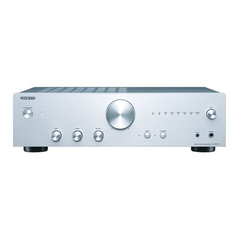
Onkyo
Onkyo DV- P303 User manual
Popular Amplifier manuals by other brands

Unison Research
Unison Research REFERENCE PRE owner's manual

Pioneer
Pioneer GM-X904 owner's manual

Rockford Fosgate
Rockford Fosgate PRIME R2-200X2 Installation & operation

Crown
Crown BCA supplementary guide

Audio Research
Audio Research REFERENCE PHONO 10 owner's manual

Audio Research
Audio Research SP9 MKIII owner's manual