HC-HOBBY A-10 Warthog Twin EOF User manual

A-10
Warthog
Twin
EOF
Assembly
Instructions
Specifications:
Wingspan:
1017mm
(40.
03in)
Length:
916mm(36.06in)
Height:284mm(11.18in)
Weight:
970g
Wingloading:
59g/dm2
Motor:
<t>30
brushless
outerrunnermotor
www.
he
hobby,
com

TABLE
OF
CONTENTS
1
,
Introduction
1
2,
Prescribed
Use1
3,
Main
Specifications
2
4,
ProductDescription
2
5,
Scope
of
Delivery
3
6,
Meaning
ofthe
Icons
4
7,
SafetyInstructions
4
8,
Notes
on
Batteries
and
RechargeableBatteries
7
9,
Transmitter'
s
Modes
and
Construction
8
10,
GettingStartedwith
the
Transmitter
10
11,
Charging
the
FlightBattery
13
12,
Assembly
14
13,
Checking
and
Setting
the
ModelFunctions
22
14,
Accessories
26

1
INTRODUCTION
Dear
customer:
Thank
youfor
purchasingthisproduct!
This
productmeets
the
requirements
of
current
European
and
nationalguidelines.
We
kindlyrequest
the
user
to
follow
the
operatinginstructions
to
preservethiscondition
and
to
ensure
safeoperation!
;
Theseoperating
instructions
belong
to
this
product.
It
contains
important
information
;;;
specific
toits
operation
and
maintenance.
Please
take
this
into
considerationwhen
I
you
pass
it
on
to
third
parties.
Please
keep
these
instructions
for
further
reference!
All
company
names
and
productdesignationscontainedherein
are
trademarks
ofthe
respective
owners.
All
rightsreserved.
2
PRESCRIBED
USE
This
product
isan
electrically
drivenmodelairplane,which
is
wirelessly
radio-controlled
via
the
remotecontrol
system
included
inthe
delivery.
The
model
is
designed
for
outdoor
use
and
should
be
flownunder
weak
winds
orin
calmweatherconditionsonly.
The
model
airplane
is
pre-assembled
andis
delivered
with
built-in
remotecontrol
and
drive
components.
The
productmust
notget
damp
or
wet.
The
product
isnot
suitable
for
childrenunder
14
years
of
age.
;
Take
note
ofallthe
safety
instructions
in
these
operating
instructions!They
contain
:
important
information
regarding
the
handling
ofthe
product.
3
MAIN
SPECIFICATIONS
Items
Wingspan:
Length:
Height:
Weight:
Wingloading:
Thrust:
Engine
type:
Ducted
fan:
Battery:
Servo:
Receiver:
Transmitter:
ESC:
Parameters
1017mm(40.
03in)
916(36.
06in)
284(11.
18in)
970g(34.
2 oz)
59g/dm2(2.
1on/sq.ft)
3=750g
(jj
30
brushless
outer
runner
motor
EOF
75X2
Li-poty2200mah
11.1V
20C
9gx4
6CH
4ch
20Ax2
4
PRODUCTDESCRIPTION
»The
design
for
dimension
and
appearance
is
based
onthe
realplane,which
gives
a
vivid
similarity
and
flying
image.
»It
is
configured
with
two
engines,which
is
4>75mm
ducted
fans
based
on
elaboratecalculation.
The
thrust
is
strong
andthe
electricity
current
is
small.
Anditis
alsoconfigured
with
two
high
KV
motors,which
is
verypowerful
to
thiskit.
1
Moduledesigned.
Itis
veryconvenient
to
repair
or
exchange
the
parts,
such
as
mainwing,
tail
wing,
ESC,
motor,
servos,
receivers,
the
controlsteel
wire
and
canopy.
»It
onlytakes
4-5
steps
todothe
assembly.
'
It
flies
stably
inlow
height
andyou
will
enjoy
thelow
height
flying
near
the
ground.
»It
very
easy
todo
take-off
and
landing.
>The
power
is
strong
andthe
maneuverability
is
nice.
Itcandoa lot
aerial
acrobatics,
such
as
flip,
loop,turnover
flying
atlow
speed
andsoon.
5
SCOPE
OF
DELIVERY
6
MEANING
OFTHE
ICONS
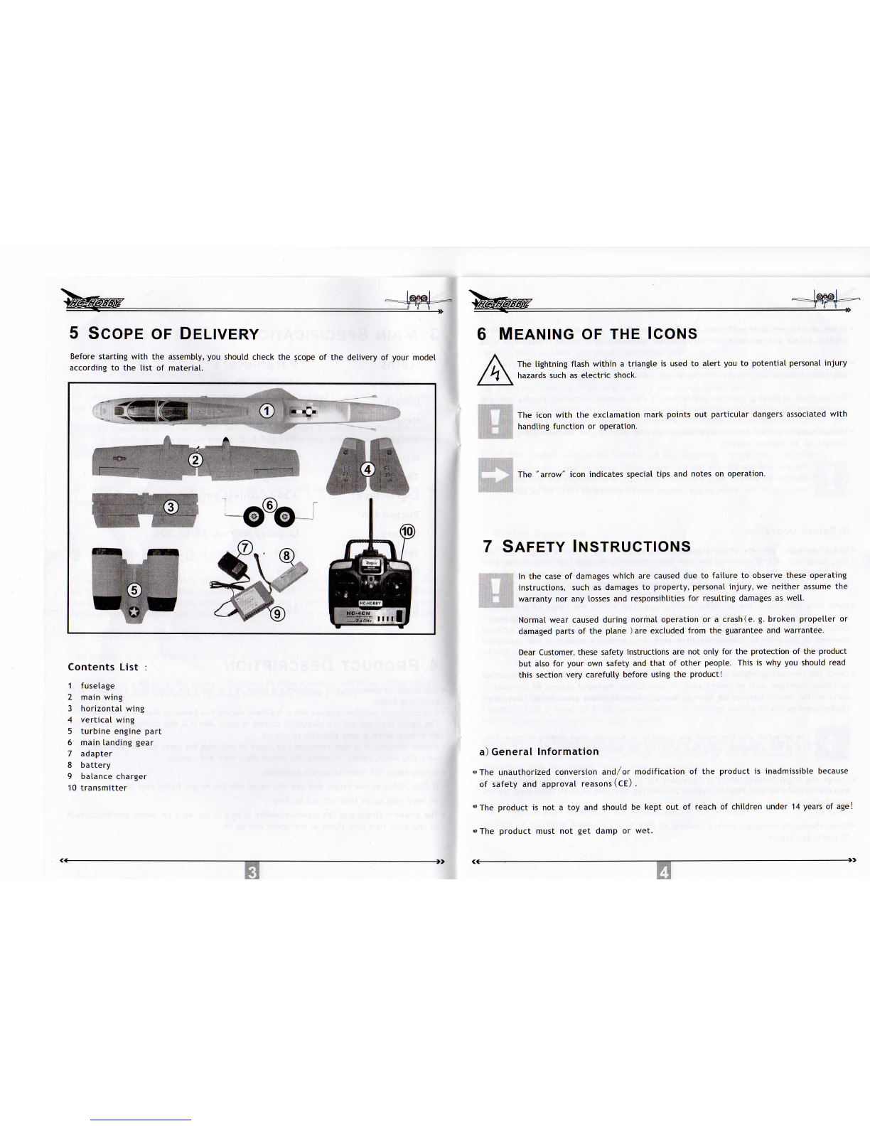
Before
starting
with
the
assembly,
you
should
check
the
scope
ofthe
delivery
of
yourmodel
according
to the
list
of
material.
Contents
List
:
1
fuselage
2
mainwing
3
horizontal
wing
4
vertical
wing
5
turbine
enginepart
6
mainlandinggear
7
adapter
8
battery
9
balancecharger
10
transmitter
The
lightningflash
within
a
triangle
is
used
to
alert
youto
potential
personal
injury
hazards
such
as
electric
shock.
The
icon
with
the
exclamationmarkpoints
out
particular
dangers
associated
with
handlingfunction
or
operation.
The
"arrow"iconindicatesspecialtips
and
notes
on
operation.
7
SAFETYINSTRUCTIONS
In
the
case
of
damages
which
are
caused
dueto
failure
to
observethese
operating
instructions,such
as
damages
to
property,personal
injury,
we
neither
assume
the
warranty
norany
losses
and
responsihlities
for
resulting
damages
as
well.
Normal
wear
caused
duringnormaloperation
ora
crash
(e.g.
brokenpropeller
or
damaged
parts
ofthe
plane
) are
excludedfrom
the
guarantee
and
warrantee.
Dear
Customer,
thesesafetyinstructions
arenot
only
forthe
protection
ofthe
product
but
also
for
your
own
safety
and
that
of
otherpeople.This
iswhyyou
shouldread
thissectionverycarefullybefore
using
the
product!
a)
GeneralInformation
«The
unauthorized
conversion
and/or
modification
ofthe
product
is
inadmissible
because
of
safety
and
approval
reasons
(CE).
"
The
product
isnota toyand
should
be
kept
outof
reach
of
childrenunder
14
years
of
age!
•
The
product
must
notget
damp
or
wet.

"If
youdonotyet
havesufficientknowledge
onhowto
deal
with
remote-controlled
models,
please
contact
an
experienced
model
sportsman
ora
model
construction
club.
•
Taking
outa
private
liability
insurance
is
recommended.
Ifyou
alreadyhaveone,
get
some
informationwhether
the
operation
ofa
model
is
covered
by
yourinsurance.
•
Donot
leavepackagingmaterialunattended.
Itmay
becomedangerousplayingmaterial
for
children!
"Should
questionsarisethat
arenot
answered
with
the
help
of
thisoperatingmanual,
contact
usor
anotherexpert.
The
useand
operation
of
remotecontrolmodelairplanes
hastobe
learned!
Ifyou
have
neversteered
such
a
model,startespecially
carefully
andget
used
tothe
reactions
ofthe
model
tothe
remotecontrol
commands
first.
Dobe
patient!
«
If
batteries
are
used
forthe
powersupply
ofthe
transmitter,make
sure
that
there
is
a
sufficient
rest
capacity
(battery
checker)
. Ifthe
batteries
are
empty,
always
replace
the
completeset,never
individual
cellsonly.
«Before
eachoperation,
control
the
settings
ofthe
steering
trim
atthe
transmitter
for
different
steeringdirectionsand,
if
necessary,
resetthem.
«
Always
switch
the
transmitter
on
first
and
make
sure
the
transimitter's
throttle
isata
minimum.
And
thenswitch
onthe
flight
battery
ofthe
model.Otherwise,unexpectedreactions
ofthe
electric
modelairplane
may
occur
andthe
propeller
can
start
to
rotate
unintentionally!
"Check
the
correct
and
secureposition
ofthe
propeller
beforeeachoperation.
»Make
sure
that
neitherobjects
nor
bodyparts
areinthe
rotating
and
suctionarea
of
the
propeller
while
itis
rotating.
b)
BeforeOperation
*
Unroll
the
wound
up
wire
ofthe
antenna
ofthe
model
toits
completelength.
The
part
that
hangs
outofthe
model
atthe
rearmustneither
be
turnedover towards
the
front
and
fastened
tothe
model
norcut
off.
The
bestreceptionresults
are
attained
ifthe
wire
hangs
loose
from
the
model
andis
draggedduring
the
flight.
•
Makesure
that
there
areno
othermodelsoperated
within
the
range
ofthe
remote
control
installation
andonthe
same
remotecontrolchannel(transmitter
frequency).
Otherwise,
you
will
losecontrolover
the
remote-controlled
model!
Always
use
different
channels
ifyou
wish
to
operatesimultaneously
twoor
severalmodels
inthe
immediate
proximity
of
each
other.
•»
Check
the
functionsafety
of
yourmodel
andthe
remote
control
installation.
Pay
attention
to
visible
damages
such
as
broken
plug-in
connectionsdamagedcables.
All
movable
parts
onthe
modelhave
tobe
smoothrunning,however,theremust
beno
tolerance
inthe
bearing.
;
r;:"
::f:
The
propeller
andthe
motor
are
mounted
atan
anglewhenlooking
at
them
first.
;,::
This
isnota
manufacturing
fault
or
defect,
but
imperative
for
aerodynamical
reasons.
»
Charge
the
flight
battery,
which
is
necessary
for
operation,
as
well
asthe
rechargeable
batteryneeded
inthe
remote
control
according
the
instructions
indicated
bythe
manufacturer.
•
Please
change
the
municipalelectricpower
of
AC
10OV-240V
and
50Hz
or
60Hz
into
the
required
DC
power
by
adapter.
C)
DuringOperation
•Donot
take
any
risks
whenoperating
the
product.
Your
own
security
and
that
of
your
environment
depends
solely
on
yourresponsibilitywhendealing
with
the
model.
•Improper
operation
can
cause
serious
damage
to
people
and
property!Therefore,during
operation,ensure
a
sufficient
safety
distance
to
persons,
animals
and
objects.
w
Select
an
appropriate
site
forthe
operation
of
yourmodelairplane.
«Fly
yourmodelonly
if
your
ability
to
respond
is
unrestricted.
The
influence
of
tiredness,
alcohol
or
medicine
can
cause
incorrect
responses.
«
Donot
direct
your modeltowardsspectators
or
towardsyourself.
•
Motor,
and
flight
battery
can
heat
up
duringoperation
ofthe
model.
Therefore,take
a
break
of
5-10minutesbefore re-chargingbattery
or
beforere-starting
with
a
possiblyexistingspare
flight
battery.
•
Always
leave
the
remotecontrol(transmitter)turned
onas
long
asthe
model
isin
operation.
Afterlanding,
always
disconnect
the
flight
batteryfirst
or
switch
the
modeloff.
Itis
only
afterwards
that
the
remotecontrol
maybe
turnedoff.
•In
case
of a
fault
or a
malfunction,correct
the
fault
first
then
re-start
the
model.
•
Don'
t
expose
yourmodel
andthe
remote
control
fora
longerperiod
of
time
to
direct
sunlight
or
excessive
heat.
8
INFORMATIONRELEVANT
TO
BATTERIES
AND9
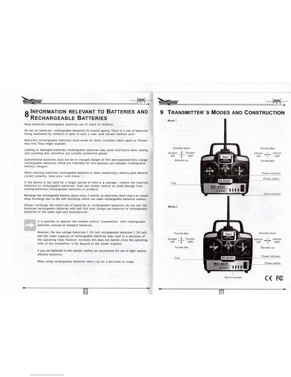
TRANSMITTER'S
MODES
AND
CONSTRUCTION
RECHARGEABLEBATTERIES
Model
Keep
batteries/rechargeable
batteries
outof
reach
of
children.
Do
notlet
batteries
/rechargeable
batteries
lie
aroundopenly.There
isa
risk
of
batteries
being
swallowed
by
children
or
pets.
In
such
a
case,
seek
instantmedicalcare!
Batteries/rechargeablebatteriesmustnever
be
short-circuited,takenapart
or
thrown
into
fire.
They
mightexplode!
Leaking
or
damagedbatteries/rechargeablebatteries
may
cause
acid
burns
whencoming
into
touchingskin,therefore
use
suitableprotectivegloves.
Conventional
batteriesmust
notbe
re-charged.
Danger
of
fire
and
explosion!Only
charge
rechargeable
batteries,which
are
intended
for
this
purpose;
use
suitablerechargeable
battery
chargers.
When
insertingbatteries/rechargeablebatteries
or
whenconnecting
a
batterypackobserve
correct
polarity(noteplus/
+and
minus/-).
Ifthe
device
isnot
used
fora
longerperiod
of
time(e.
g.
storage),
remove
the
inserted
batteries
(or
rechargeablebatteries)from
the
remotecontrol
to
avoiddamagefrom
leakingbatteries/rechargeablebatteries
or
products.
Recharge
the
rechargeablebatteryaboutevery
3
months,
as
otherwise,there
maya so
called
deep
discharge
duetothe
self-discharge,
which
can
makerechargeablebatteries
useless.
Always
exchange
the
entire
setof
batteries
or
rechargeablebatteries.
Donotmix
full
batteries/rechargeablebatteries
with
half-full
ones.
Always
use
batteries
or
rechargeable
batteries
ofthe
same
type
and
manufacturer.
Itis
possible
to
operate
the
remotecontrol(transmitter)
with
rechargeable
batteries
instead
of
standard
batteries.
However,
thelow
voltage
(batteries=1.
5V/cell,rechargeable
batteries=1.
2V/cell)
and
the
lowercapacity
of
rechargeablebatteries
does
lead
toa
decrease
of
the
operating
time.
However,normallythis
does
not
matter,
since
the
operating
time
ofthe
transmitter
isfar
beyond
ofthe
modelairplane.
If
youuse
batteries
inthe
remotecontrol,
we
recommend
theuseof
hight-quality
alkalinebatteries.
When
usingrechargeable
batteries
there
canbea
decrease
in
range.
Elevator
down
Rudder
.
f
Rudder
left
"'!
right
Elevator
up
Throttle
Max
Aileron
.
'f.
Aileron
left
right
Throttle
Min
Servoreverse
ce

THE
POSSIBLEPROBLEMS
AND
SOLUTIONS
Phenomenons
Motordoes
notrun
Can
not
fly
straight
Can
not
climb
Limited
control
range
Problems
1.
Battery
isnot
fullycharged.
2.The
circuit
in
model
has
been
damaged
duetoCra
sh.
1.
The
rudder
isnotonthe
centerposition.
2.The
mainwing
hasnot
been
installed
onthe
fuselagecenter
1.
The
battery
isnot
fullycharged.
2.
The
elevator
declinesdownward.
1.
The
batteries
are
almostflat
2.
The
transmitteraerial
isnot
fully
extended
Solutions
1.
Charge
the
battery.
2.
Install
newdry
cells.
3.
Contact
the
distributor.
4.
Reassembly
1.
Adjust
the
trim
onthe
transmitter.
2.
Reinstall
the
mainwing.
1.
Charge
the
battery
2.
Adjust
the
trim
onthe
Transmitter.
1.
Install
new
batteries
2.
Fullyextend
the
transmitter
aerial
10
GETTINGSTARTEDWITH
THE
TRANSMITTER
Please
note:
:::;;;:,,;:;:;
Inthe
operating
Instructions,
the
numbers
inthe
text
alwaysrefer
tothe
figureopposite
orthe
figures
within
the
section.
Cross
references
to
other
figures
are
indicated
with
the
respectivefigurenumber.
a)
Inserting
the
Batteries/RechargeableBatteries
For
the
powersupply
ofthe
transmitter
you
will
need
eight
mignon
alkaline
batteries
or
rechargeablebatteries
(AA).
For
ecological
and
also
economical
reasons,
itis
recommended
touse
rechargeable
batteries,
sincethey
canbe
recharged
inthe
transmitter
viaa
built-in
chargingsocket.
To
insert
the
batteries
or
rechargeable
batteries,
procedures
areas
follows.
The
batterycompartment
lid(1)
Is
located
on
the
rearside
ofthe
transmitter.
Please
press
the
corrugated
triangle
and
push
offthelid
downward.
Now
insert
the
eight
batteries
or
rechargeable
batteries
inthe
battery
compartment.Observe
the
correct
polarity
ofthe
individual
cells.
A
corresponding
note(3)
is
located
onthe
bottom
ofthe
batterycompartment.
Afterwards,
slide
thelidofthe
battery
compartmentback
on
from
the
bottom
andlet
the
lockingmechanism
click
into
place.
Either
a
teacher/studentcable
with
a 3.5mm
jackconnector
oran
interface
cable
for
flight
simulator
canbe
connected
canbe
connected
tothe
student
socket.
b)
ChargingRechargeableBatteries
inthe
Transmitter
The
transmitter
is
equipped
with
a
charge
socket
to
charge
the
insertedrechargeable
batteries.
Please
pay
attention
tothe
following
safety
instructions
and
information:
|
Ifthe
transmitter
is
turned
on,
please
donot
connect
the
adapter
with
the
battery
(1.
5V/cell)
must
notbe
recharged.There
isa
risk
of
fire
and
explosion!
Only
chargerechargeablebatteries
(1.
2V/cell)intended
for
thispurpose.
The
transmitter
hastobe
switched
off
during
the
charging
process.
Please
also
observe
the
correct
polarity
ofthe
connectorplug.
The
innercontact
of
the
charge
socket
hastobe
connected
tothe
plusconnection
(+)andthe
outside
contact
tothe
minusconnection
(-)ofthe
charger.
The
chargingcurrentshould
be
approx.
1/10
ofthe
capacityvalue
ofthe
inserted
rechargeable
batteries.
For
rechargeablebatteries
with
a
capacity
of
2000
mAh
this
corresponds
toa
chargingcurrent
of
approx.
200
mA
andthe
charging
time
takes
approx
14
hours.
In
order
to
avoid
damages
of
internal
circuit
paths
and
connections
don'
t use
fast
chargers.
please
Since
a
protectivediode
is
integrated
inthe
transmitter,
donotuse
chargers
that
briefly
interrupt
the
chargingcurrent
in
order
to
measure
the
current
rechargeable
batteryvoltage
in
this
case,
the
rechargeablebatteriesmust
be
removed
from
the
transmitter.
With
NiCd
rechargeablebatteries
a
memoryeffect
can
occur.
If
NiCd
rechargeable
batteries
are
chargedwhenthey
arenot
fully
discharged,
their
capacity
diminishes
inthe
course
of
time.
Thus,
such
rechargeablebatteries
must
be
discharged
with
an
appropriatechargeroutside
ofthe
transmitter
and
thenchargedcompletelyagain.
c)
Switching
the
Transmitter
On/off
Attention!
•
The
flight
control
system
inthe
model
is
equipped
with
an
effectiveprotective
I
circuit
which
later
prevents
the
unintentionalstart-up
of
the
drivemotor.
llS;
However,
before
each
operation
ofthe
transmitter,
you
must
ensure
that
the
controlstick
forthe
motor
rotation
speed
isin
the
Motor
off
position.
For
thispurpose,
the
controlstick
hastobe
pushed
downcompletely
or
pulled
towards
youasfaras
possible.
Sine
unlike
with
the
controlfunctions
of
the
rudder,
there
isno
resetspring
forthe
stickfunction
forthe
motor
rotation
speed,
the
controlstick
always
remains
inthe
previously
set
position.
When
the
rechargeablebatteries
are
charged
or
when
new
batteries
are
inserted,
for
test
purposes,
switch
the
transmitter
onviathe
functionswitch.
TheLED
displayglows
redand
signals
an
adequatepowersupply
tothe
transmitter.
Ifthe
power
supply
does
not
suffice
forthe
transmitter
to
workproperly(lowerthan
8.8V)
the
LED's
red
light
will
be
continuousflashing.
In
this
case,
you
shouldstopoperating
yourmodel
as
quickly
as
possible.
For
furtheroperation
ofthe
transmitter
the
rechargeablebatteries
aretobe
recharged
or
new
batteriesmust
be
inserted.

11
CHARGING
THE
FLIGHT
BATTERY
12
ASSEMBLY
Before
the
final
assembly
ofthe
model.
You
should
charge
the
flight
battery
(1).
An
appropriate
plug-in
battery
charger(2)
is
included
inthe
delivery.
Connect
the
flight
battery
with
the
connectors
(3)ofthe
plug-in
charger.
The
connector
or
socket
ofthe
plug-in
charger
hastobe
connected
tothe
socket
or
connector
onthe
batterycable.
Then
connect
the
plug-in
charger
toa
100V-240V,
50Hz/60Hz
mains
socket.
;
For
photo-technical
reasons,
the
chargingcable
ofthe
plug-in
charger
is
:
illustrated
in
wound
up
state.Before
the
first
use,
the
cableretainershould
be
opened
andthe
cable
be
unwound.
Safety
Instruction
of
Li-Polybattery
1.
Donot
disassemble
or
reconstruct
the
battery.
2.
Donot
short-circuit
the
battery.
3.
Donotuseor
leave
the
batterynearby
the
fire,
stove
or
heatedplace(morethan
80°C).
4.
Donot
immerse
the
battery
in
water
or
fire.
5.
Donot
charge
the
batteryunder
the
blazingsunlight.
6.
Donot
drive
a
nail
into
the
battery,strike
itby
hammer
or
tread
it.
7.
Donot
impact
or
toss
the
battery.
8.
Donotusethe
battery
with
conspicuous
damage
or
deformation.
9.
Donot
make
the
directsoldering
onthe
battery.
10.
Donot
reverse
charge
or
over
discharge
the
battery.
11.
Donot
reverse
charge
or
reverse
connect.
12.
Donot
connect
the
battery
tothe
ordinarychargersocket
orcar
cigarettejack.
13.
Donotusethe
battery
for
unspecifiedequipment.
14.
Donot
touch
the
leakingbattery
directly,
please
wash
yourskin
or
clothes
with
water
if
they
are
bedewed
by
liquid
leaking
from
the
battery.
15.
Donotmixthe
Li-Polybattery
with
other
un-chargeable
battery
in
using.
16.
Donot
continuecharging
the
batteryover
the
prescribed
time.
17.
Donotputthe
battery
into
the
microwaveoven
or
high-pressurecontainer.
18.
Donotusethe
abnormalbattery.
19.
Donotuseor
keep
the
batteryunder
the
sunlight.
20.
Donotusethe
batterynearby
the
placewheregeneratesstatic
electricity
(over
64V).
21.
Donot
charge
the
batterywhen
the
environmentaltemperature
is
under
0°C
orover45t.
22.
Ifyou
find
the
battery
leaking,smelling
or
abnormal,stop
using
itand
return
ittothe
seller.
23.
Keep
the
battery
away
from
the
children.
24.
Usethe
specified
charger
and
observe
charging
requirement.
25.
When
using
by
minors,parents
should
show
them
tothe
correctinstruction.
Cautions
1.
Be
fully
chargedunder
no
morethan
1A
voltage
by
using
the
specifiedcharger.
2.
Be
discharged
10C
voltage
but
avoiding
discharge
time
too
long
to
harm
the
battery.
.
3.
Repeat
the
first
and
second
step
oneortwo
times.
1.
Thismanual
will
help
you
assembleyour
A-10
step-by-step.
It
does
assume
that
this
isnot
your
first
airplane.
Ifyou
need
assistance,
please
aska
local
flyer,
visit
www.
he-hobby,
com,
or
call
us.
Let'
s
start
by
gluing
thetwo
mainwingpanelstogether.
Use
5
minute
epoxy
for
this
step.Makesure
that
the
aileronservowires
are
routed
to
the
top-side
ofthe
wingpanels.
After
the
epoxy
has
set,
itis
time
toadd
the
carbontubereinforcement
tothe
center
section
ofthe
wing-Mix
a
smallamount
of
5-minute
epoxy
and
spread
it
along
the
groove
inthe
bottomcenter
ofthe
wing.
Press
the
carbontube
in
position
andlet
the
epoxyset.
3.
Glue
the
foam
filler
into
the
space
onthe
bottom
ofthe
wing.
4.
Locate
the
blackplasticwinglocator
and
use
itto
press
a
dent
into
the
front
edge
ofthe
wings.Withyour
hobby
knife
cuta
small
groove
forthe
plasticpart.
,'*
i
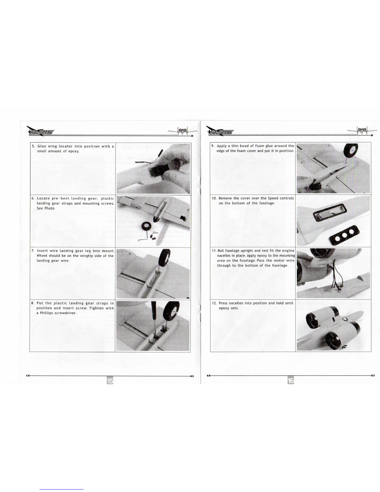
5.
Glue
wing
locator
into
position
with
a
smallamount
of
epoxy.
6.
Locate
pre-bent
landinggear,plastic
landing
gearstraps
and
mountingscrews.
See
Photo
7.
Insert
wire
landing
gear
leg
into
mount.
Wheel
should
beonthe
wingtip
side
ofthe
landinggear
wire.
"
„.
o
Put
the
plastic
landing
gearstraps
in
position
and
insert
screw.
Tighten
with
a
Phillips
screwdriver.
9.
Apply
a
thin
bead
of
foamgluearound
the
edge
of the
foamcover
and put it in
position.
10.
Remove
the
coverover
the
Speed
controls
on
the
bottom
ofthe
fuselage.
11.
Rollfuselage
upright
and
test
fitthe
engine
nacelles
in
place.
Apply
epoxy
tothe
mounting
area
onthe
fuselage.
Pass
the
motor
wire
through
tothe
bottom
ofthe
fuselage.
12.
Press
nacelles
into
position
and
hold
until
epoxy
sets.
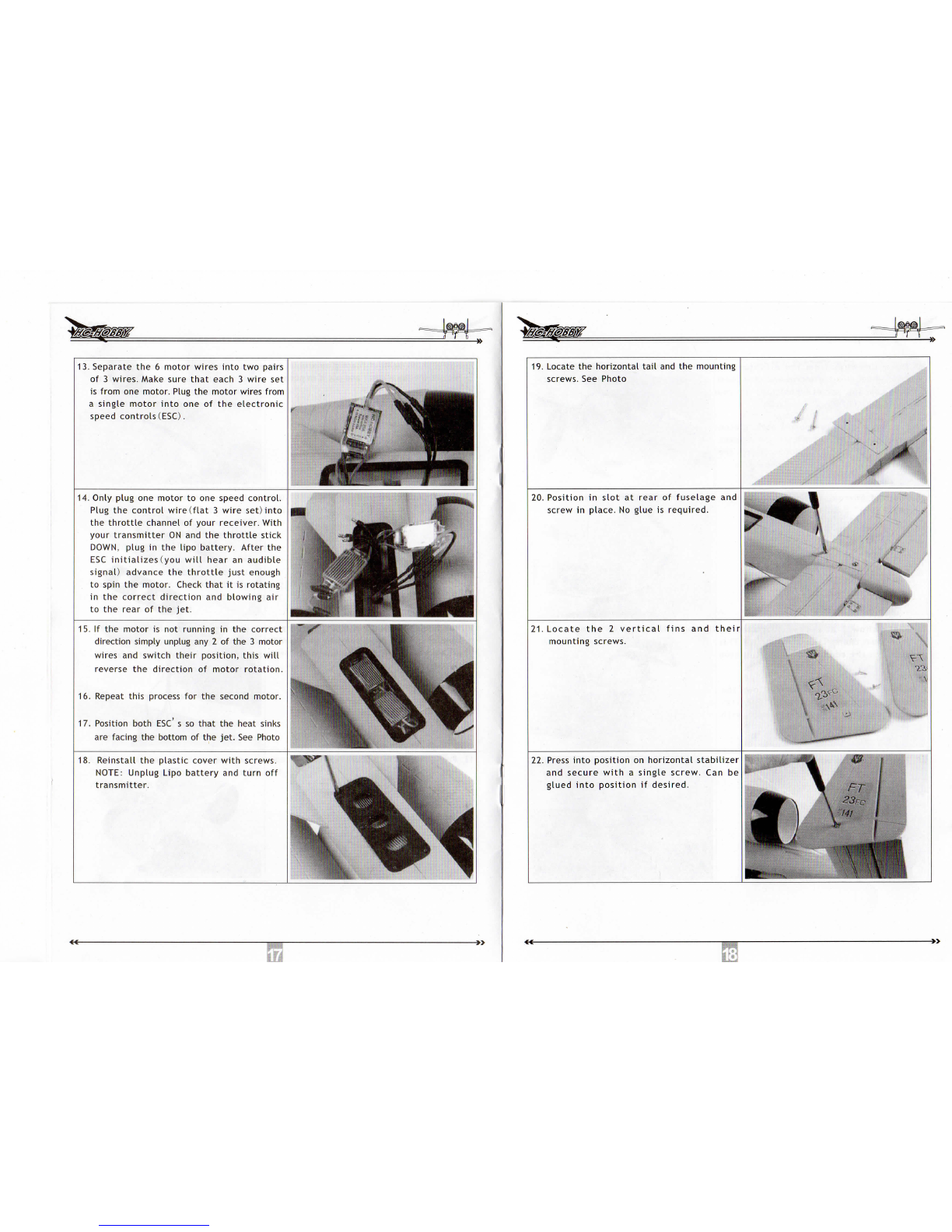
13.
Separate
the6
motorwires
into
two
pairs
of3
wires.Make
sure
that
each
3
wire
set
is
from
one
motor.
Plug
the
motorwiresfrom
a
singlemotor
into
oneofthe
electronic
speed
controls
(ESC).
14.
Onlyplug
one
motor
toone
speed
control.
Plug
the
controlwire
(flat
3
wire
set)
into
the
throttle
channel
of
yourreceiver.With
yourtransmitterONandthe
throttle
stick
DOWN,
plug
inthe
lipo
battery.After
the
ESC
initializes
(you
will
hear
an
audible
signal)
advance
the
throttle
justenough
to
spin
the
motor.
Check
that
itis
rotating
inthe
correctdirection
and
blowing
air
tothe
rear
ofthe
jet.
15.
Ifthe
motor
isnot
running
inthe
correct
directionsimplyunplug
any2 ofthe3
motor
wires
and
switch
their
position,this
will
reverse
the
direction
of
motorrotation.
I
16.
Repeat
this
process
forthe
second
motor.
,
17.
Positionboth
ESCs so
that
the
heat
sinks
are
facing
the
bottom
ofthe
jet.
See
Photo
18.
Reinstall
the
plasticcover
with
screws.
NOTE:
UnplugLipobattery
and
turn
off
transmitter.
inn
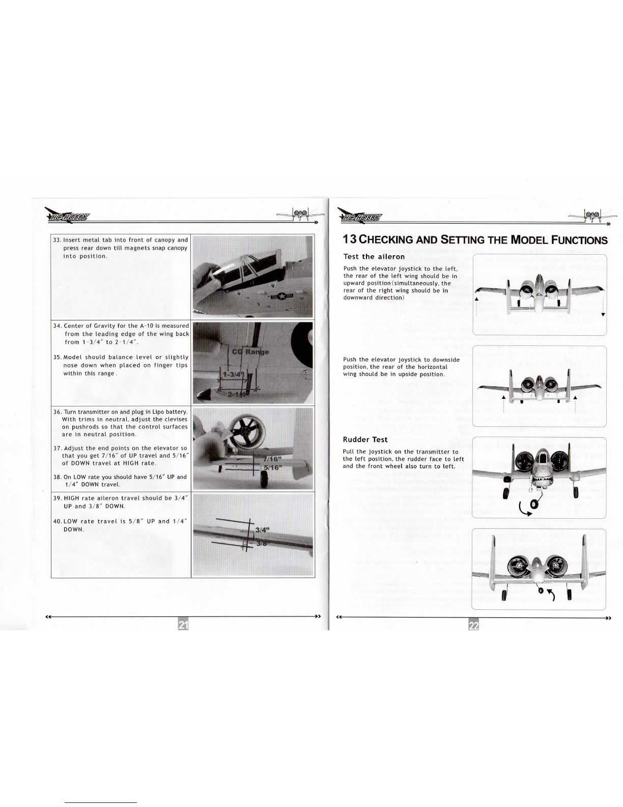
19.
Locate
the
horizontal
tail
andthe
mounting
screws.
See
Photo
20.
Position
in
slot
at
rear
of
fuselage
and
screw
in
place.
No
glue
is
required.
21.
Locate
the2
vertical
fins
and
their
mounting
screws.
•
22.
Press
into
position
on
horizontalstabilizer
and
secure
with
a
singlescrew.
Canbe
glued
into
position
if
desired.

23.
Trace
the
wiresfrom
the
elevator
and
nose
wheelsteering
servos
and
plugthem
into
the
appropriatepositions
onyou
receiver.
24.
Ifyouare
going
to
controlboth
aileron
servos
from
a
singlechannel
onthe
receiver,
plug
the
supplied
"Y"
connector
into
the
Aileronchannel
on
receiver.
See
Photo.
25.
Photo
of
Aileronsconnected
toa
single
channel
"Y"
connector.
26.
Photoshow
2
ailerons
controlled
by
individual
channels
onthe
receiver.This
requires
the
addition
of2
shortaileron
extensions
(notincluded).
27.
Separate
aileron
channelsallows
the
programming
of
aileron
differential
for
smoother
turn
performance
with
less
adverse
yaw.
28.
Positionwing
in
wingsaddle.
~[sr
29.
Screw
in
place
with
supplied
screws.
30.
Epoxy
Velcrostrap
in
batterybox.
31.
Afterepoxy
has
set,
install
lipo
battery
per
photo.
32.
Close
Velcro
to
holdbattery
in
position.
i
T
33.
Insert
metal
tab
into
front
of
canopy
and
press
rear
down
till
magnets
snap
canopy
into
position.
34.
Center
of
Gravity
forthe
A-10
is
measured
from
the
leadingedge
ofthe
wing
back
from
1-3/4"
to
2-1/4".
35.
Modelshouldbalance
level
or
slightly
nose
downwhenplaced
on
fingertips
within
this
range
.
36.
Turn
transmitter
on and
plug
in
Lipobattery.
Withtrims
in
neutral,adjust
the
clevises
on
pushrods
so
that
the
control
surfaces
are
in
neutralposition.
37.
Adjust
theend
points
onthe
elevator
so
that
youget
7/16"
ofUP
travel
and
5/16"
of
DOWN
travel
at
HIGH
rate.
38.
On LOW
rate
you
should
have
5/16"
UP and
1/4"
DOWN
travel.
39.
HIGH
rateailerontravelshould
be
3/4"
UP
and
3/8"
DOWN.
40.
LOW
rate
travel
is
5/8'
DOWN.
UP
and
1/4"
13
CHECKING
AND
SETTING
THE
MODELFUNCTIONS
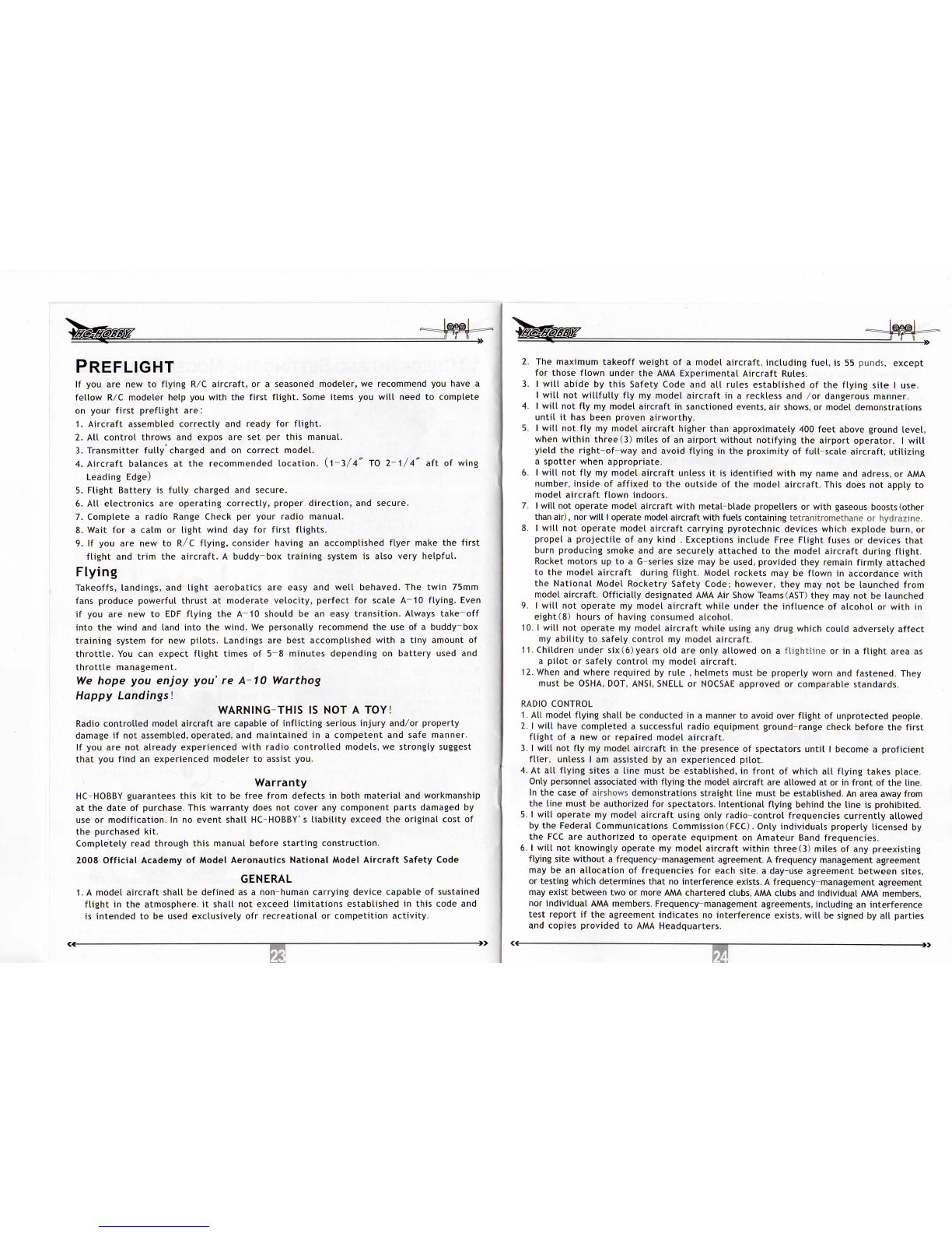
Test
the
aileron
Push
the
elevatorjoystick
tothe
left,
the
rear
ofthe
left
wing
should
bein
upward
position(simultaneously,
the
rear
ofthe
right
wing
should
bein
downward
direction)
Push
the
elevatorjoystick
to
downside
position,
the
rear
ofthe
horizontal
wing
should
bein
upsideposition.
Rudder
Test
Pull
the
joystick
onthe
transmitter
to
the
left
position,
the
rudderface
to
left
and
the
front
wheel
also
turn
to
left.
illfl
PREFLIGHT
Ifyouarenewto
flying
R/C
aircraft,
ora
seasoned
modeler,
we
recommend
you
have
a
fellow
R/C
modelerhelp
you
with
the
first
flight.
Some
items
you
will
need
to
complete
on
your
first
preflight
are:
1.
Aircraftassembledcorrectly
and
ready
for
flight.
2.All
controlthrows
and
expos
aresetper
this
manual.
3.
Transmitter
fully
charged
andon
correct
model.
4.
Aircraft
balances
atthe
recommended
location.
(1-3/4"
TO
2-1/4"
aftof
wing
Leading
Edge)
5.
Flight
Battery
is
fully
charged
and
secure.
6.
All
electronics
are
operatingcorrectly,proper
direction,
and
secure.
7.
Complete
a
radio
Range
Check
per
yourradiomanual.
8.
Wait
fora
calm
or
light
wind
dayfor
first
flights.
9.
IfyouarenewtoR/C
flying,
considerhaving
an
accomplished
flyer
make
the
first
flight
and
trim
the
aircraft.
A
buddy-box
training
system
is
alsovery
helpful.
Flying
Takeoffs,
landings,
and
light
aerobatics
are
easy
and
well
behaved.
The
twin
75mm
fans
producepowerful
thrust
at
moderate
velocity,
perfect
for
scale
A-10
flying.
Even
ifyouarenewto
EOF
flying
the
A~10
should
bean
easy
transition.
Always
take-off
into
the
wind
and
land
into
the
wind.
We
personallyrecommend
theuseofa
buddy-box
training
system
fornew
pilots.
Landings
are
bestaccomplished
with
a
tiny
amount
of
throttle.
Youcan
expect
flight
times
of
5~8
minutesdepending
on
battery
used
and
throttle
management.
We
hope
you
enjoy
you'
re
A-10
Warthog
Happy
Landings!
WARNING-THIS
ISNOTA
TOY!
Radio
controlled
model
aircraft
are
capable
of
inflicting
serious
injury
and/orproperty
damage
ifnot
assembled,operated,
and
maintained
ina
competent
and
safemanner.
Ifyouarenot
alreadyexperienced
with
radio
controlled
models,
we
strongly
suggest
that
you
find
an
experiencedmodeler
to
assist
you.
Warranty
HC-HOBBY
guarantees
this
kittobe
freefromdefects
in
both
material
and
workmanship
atthe
date
of
purchase.Thiswarranty
does
not
cover
any
componentpartsdamaged
by
use
or
modification.
Inno
eventshall
HC-HOBBY'
s
liability
exceed
the
original
cost
of
the
purchasedkit.
Completelyreadthroughthismanualbeforestartingconstruction.
2008Official
Academy
of
Model
Aeronautics
National
Model
Aircraft
Safety
Code
GENERAL
1.
A
modelaircraftshall
be
defined
asa
non-humancarryingdevicecapable
of
sustained
flight
inthe
atmosphere,
it
shall
not
exceed
limitations
established
in
thiscode
and
is
intended
tobe
used
exclusively
ofr
recreational
or
competition
activity.
Si
"
2.
The
maximumtakeoffweight
ofa
modelaircraft,
including
fuel,
is55
punds,
except
for
thoseflownunder
theAMA
ExperimentalAircraftRules.
3.
I
will
abide
by
this
Safety
Code
andall
rulesestablished
ofthe
flying
site
I
use.
I
will
not
willfully
flymy
modelaircraft
ina
reckless
and
/or
dangerousmanner.
4.
I
will
notflymy
modelaircraft
in
sanctionedevents,
air
shows,
or
modeldemonstrations
until
ithas
beenprovenairworthy.
5.
I
will
notflymy
modelaircraft
higher
thanapproximately
400
feet
above
ground
level,
when
within
three(3)
miles
ofan
airportwithout
notifying
the
airportoperator.
I
will
yield
the
right-of-way
and
avoid
flying
inthe
proximity
of
full-scale
aircraft,
utilizing
a
spotter
when
appropriate.
6.
I
will
notflymy
modelaircraft
unless
itis
identified
with
my
name
and
adress,
orAMA
number,inside
of
affixed
tothe
outside
ofthe
model
aircraft.
This
does
not
apply
to
modelaircraft
flown
indoors.
7.
I
will
not
operatemodel
aircraft
with
metal-blade
propellers
or
with
gaseous
boosts
(other
than
air),
nor
will
I
operatemodelaircraft
with
fuelscontainingtetranitromethane
or
hydrazine.
8.
I
will
not
operatemodelaircraftcarryingpyrotechnicdeviceswhichexplode
burn,
or
propel
a
projectile
ofany
kind
.
Exceptions
include
Free
Flight
fuses
or
devices
that
burn
producingsmoke
andare
securelyattached
tothe
modelaircraftduring
flight.
Rocket
motors
uptoa
G-seriessize
maybe
used,providedtheyremain
firmly
attached
tothe
model
aircraft
during
flight.
Modelrockets
maybe
flown
in
accordance
with
the
NationalModelRocketrySafety
Code;
however,they
maynotbe
launchedfrom
model
aircraft.
Officiallydesignated
AMAAir
Show
Teams
(AST)
they
maynotbe
launched
9.
I
will
not
operate
my
model
aircraft
while
under
the
influence
of
alcohol
or
with
in
eight(8)
hours
of
having
consumed
alcohol.
10.
I
will
not
operate
my
modelaircraft
while
using
any
drugwhichcouldadverselyaffect
my
ability
to
safelycontrol
my
modelaircraft.
11.
Childrenunder
six
(6)
years
oldare
onlyallowed
ona
flightline
orina
flight
area
as
a
pilot
or
safelycontrol
my
modelaircraft.
12.
When
and
whererequired
by
rule
,
helmetsmust
be
properlyworn
and
fastened.They
must
be
OSHA,
DOT,
ANSI,
SNELL
or
NOCSAE
approved
or
comparablestandards.
RADIO
CONTROL
1.
All
model
flying
shall
be
conducted
ina
manner
to
avoidover
flight
of
unprotectedpeople.
2.
I
will
have
completed
a
successful
radioequipmentground-rangecheckbefore
the
first
flight
ofa newor
repairedmodelaircraft.
3.
I
will
notflymy
modelaircraft
inthe
presence
of
spectators
until
I
become
a
proficient
flier,
unless
I am
assisted
byan
experienced
pilot.
4.
Atall
flying
sites
a
line
must
be
established,
in
front
of
which
all
flying
takesplace.
Only
personnel
associated
with
flying
the
modelaircraft
are
allowed
atorin
front
ofthe
line.
In
the
case
of
airshows
demonstrationsstraight
line
must
be
established.
An
areaawayfrom
the
line
must
be
authorized
for
spectators.
Intentional
flying
behind
the
line
is
prohibited.
5.
I
will
operate
my
modelaircraftusingonly
radio-control
frequencies
currently
allowed
by
the
FederalCommunications
Commission
(FCC).
Onlyindividualsproperlylicensed
by
theFCCare
authorized
to
operateequipment
on
Amateur
Band
frequencies.
6.
I
will
not
knowinglyoperate
my
modelaircraft
within
three
(3)
miles
ofany
preexisting
flyingsite
without
a
frequency-managementagreement.
A
frequencymanagementagreement
may
bean
allocation
of
frequencies
for
each
site,
a
day-useagreementbetweensites,
or
testingwhichdeterminesthat
no
interference
exists.
A
frequency-managementagreement
may
existbetween
twoor
more
AMA
charteredclubs,
AMA
clubs
and
individual
AMA
members,
nor
individual
AMA
members.Frequency-managementagreements,
including
an
interference
testreport
ifthe
agreementindicates
no
interferenceexists,
will
be
signed
byall
parties
and
copiesprovided
toAMA
Headquarters.

7.
With
the
exception
of
eventsflownunder
official
AMA
rules,
no
poweredmodel
may
be
flown
outdoorscloserthan
25
feet
toany
individual,
except
forthe
pilot
and
located
atthe
flight
line.
8.
Under
no
circumstances
maya
pilot
or
other
person
touch
a
model
aircraft
in
flight
while
itis
still
underpower,except
to
divert
it
from
striking
an
individual.
9.
Radio-controlled
night
flying
is
limited
to
low-performancemodel
aircraft
(less
than
100
mph).The
model
aircraft
must
be
equipped
with
a
lighting
systemwhich
clearly
defines
the
aircraft'
s
attitude
and
direction
atall
times.
10.
The
operator
ofa
radio-controlled
model
aircraft
shall
control
it
during
the
entire
flight,
maintaining
visual
contact
without
enhancement
other
than
by
corrective
lenses
that
are
prescribed
forthe
pilot.
No
model
aircraft
shall
be
equipped
with
deviceswhich
allow
ittobe
flown
toa
selected
location
which
is
beyond
the
visual
range
ofthe
pilot.
PARK
FLYERSAFEOPERATIONRECOMMENDATIONS
Inspectyourmodelbeforeeveryflight
to
makecertain
itis
airworthy.
Be
aware
ofany
otherradiofrequencyuser
whomay
present
an
interferenceproblem.
Always
be
courteous
and
respectful
of
otherusers
of
yourselectedflightarea.
Choose
an
areaclear
of
obstacles
and
largeenough
to
safelyaccommodateyourflying
activity.
Makecertainthisarea
is
clear
of
friends
and
spectatorsprior
to
launchingyouraircraft.
Be
aware
of
otheractivities
inthe
vicinity
of
yourflightpaththatcouldcausepotential
conflict.
Carefullyplanyour
flight
pathprior
to
launch.
Abide
byanyandall
established
AMA
NationalModelAircraftSafetyCode.
14TECHNICAL
SPECIFICATIONS
No:70001
Fuselage
No:70002
mainwing
No:70003
vertical
wing
No:70004
horizontal
wing
No:70005
ducted
fan
No:70006
landing
gear
No:70008
turbine
enginepart
No:70007
controlsteel
wire
No:500001
battery
No:700002
ESC
Table of contents
Popular Motorized Toy Car manuals by other brands

REVELL
REVELL Ferrari California Assembly instructions

Kidzone
Kidzone Licensed McLaren 765LT Ride ON owner's manual

Time for Machine
Time for Machine Glorious Cabrio 2 Assembly instructions

marklin
marklin VW Käfer Einsatzfahrzeug user manual

Tameo Kits
Tameo Kits TMK 222 Assembly manual

Jamara
Jamara 405170 instruction manual

ROBBE
ROBBE Tunin chassis 1:10 4WD Elektro operating instructions

Hunter Products
Hunter Products BBH-958 owner's manual

Kyosho
Kyosho MINI-Z Racer MR-02 RM Type instruction sheet

Arrma
Arrma RAIDER XL instruction manual

Carrera RC
Carrera RC Inferno 2 Assembly and operating instructions

Reely
Reely Generation X 3 operating instructions


