HD Communications HD28650 User manual

HD COM
IN WALL BOX ACCESS POINT
Model :
HD28650

In Wall Access Point
2
Copyright Notice
Copyright © 2005-2015 HD COM Technologies Inc. All rights reserved. No part of this document may
be copied, reproduced, or transmitted by any means, for any purpose without prior written permission.
Protected by TW patent 223184, JPN patent 3099924 and China patent ZL 03 2 04640.5.
Disclaimer
We shall not be liable for technical or editorial errors or omissions contained herein; nor for incidental or
consequential damages resulting from furnishing this material, or the performance or use of this
product. We reserve the right to change the product specification without notice. Information in this
document may change without notice.
Trademarks
Microsoft Win98, Windows 2000 and WinXP are registered trademarks of Microsoft Corporation.
General:All other brand and product names mentioned herein may be registered trademarks of their
respective owners. Customers should ensure that their use of this product does not infringe upon any
patent rights. Trademarks mentioned in this publication are used for identification purposes only and
are properties of their respective companies.

In Wall Access Point 3
Table of Contents
1Introduction------------------------------------------------------------------------------------------------------------5
1-1 Package Contents ---------------------------------------------------------------------------------------------------5
1-2 Features----------------------------------------------------------------------------------------------------------------6
1-3 Precautions------------------------------------------------------------------------------------------------------------6
1-4 Outlook------------------------------------------------------------------------------------------------------------------6
1-4-1 Top Panel ----------------------------------------------------------------------------------------------------6
1-4-2 Rear Panel---------------------------------------------------------------------------------------------------7
1-5 Technical Specifications -------------------------------------------------------------------------------------------7
1-5-1 Hardware Specifications---------------------------------------------------------------------------------7
1-5-2 Software Specifications ----------------------------------------------------------------------------------8
2Installation -------------------------------------------------------------------------------------------------------------9
2-1 Installation Requirements----------------------------------------------------------------------------------------10
2-2 Getting Start---------------------------------------------------------------------------------------------------------12
3 Configuring the In Wall Access Point -----------------------------------------------------------------------------16
3-1 Internet Setting -----------------------------------------------------------------------------------------------------18
3-1-1 TCP/IP Setting--------------------------------------------------------------------------------------------18
3-2 Wireless --------------------------------------------------------------------------------------------------------------20
3-2-1 Wireless Basic Setting----------------------------------------------------------------------------------20
3-2-2 Wireless Advanced Setting----------------------------------------------------------------------------21
3-2-3 Wireless Security Setting------------------------------------------------------------------------------22
3-3 Advanced ------------------------------------------------------------------------------------------------------------25
3-3-1 Management----------------------------------------------------------------------------------------------25
3-3-2 Firmware ---------------------------------------------------------------------------------------------------27
3-3-3 Configuration----------------------------------------------------------------------------------------------29
3-3-4 SNMP-------------------------------------------------------------------------------------------------------31
3-3-5 System------------------------------------------------------------------------------------------------------32
3-3-6 Ping Command-------------------------------------------------------------------------------------------32

In Wall Access Point
4
3-4 Advanced ------------------------------------------------------------------------------------------------------------32
3-4-1 Restart------------------------------------------------------------------------------------------------------32
3-4-2 Logout ------------------------------------------------------------------------------------------------------34
Appendix A Signal Connection Arrangements--------------------------------------------------------------------34
Appendix B Regulations/EMI Compliance -------------------------------------------------------------------------35
LIMITED WARRANTY---------------------------------------------------------------------------------------------------36

In Wall Access Point 5
1 Introduction
The HD28650 Access Device revolutionizes the way wireless and wired IP-based services are
delivered to hospitality and residential properties. The HD28650 integrates wired and wireless
connectivity into a small unit that can be quickly and discretely installed in a standard wall box. The
HD28650 provides One Ethernet ports, a 2.4GHz 802.11b/g/n wireless access point. The HD28650
requires a single powered cable drop to unlock its utility and, through the reduction in cabling, switch
ports, and power-sourcing equipment, the HD28650 represents the best value for the delivery of next
generation entertainment services.
1-1 Package Contents
Please inspect your package. The following items should be included:
◎HD28650
One In Wall Access Pointt
One Telephone Cable (10cm)
One UTP Ethernet/Fast Ethernet cable (Cat.5 Twisted-pair)
One Wall Faceplate(Top and Bottom )
Bracket (EU STD*2/Set JPN STD*1/Set)
One Quick Installation Guide
If any of the above items are damaged or missing, please contact your dealer immediately.

In Wall Access Point
6
1-2 Features
Wireless data rates up to 150Mbps
Comprehensive security
64/128-bit WEP encryption
WPA encryption
WPA2 encryption
Intelligent Management
1-3 Precautions
Never remove or open the cover. You may suffer serious injury if you touch these parts.
Never install the system in the wet locations.
1-4 Outlook
Figure 1 In Wall Box Access PointOutlook
1-4-1 Top Panel
The top panel of the In Wall Box Access Pointis shown below.
Figure 2 In Wall Box Access PointTop Panel
LEDs Indication
LED State Description
Off The In Wall Box Access Pointis not receiving electrical power.PWR
Green The In Wall Box Access Pointis receiving electrical power.
Off The In Wall Box Access Pointstatus is defective.
Green The In Wall Box Access Pointstatus is complete.
SYS
Green (Blinking) During firmware upgrades, this system LED will blink.
Off Port has not established any network connection.
Yellow A port has established a valid 10/100Mbps network connection.
LINK / WAN
Yellow (Blinking) 10/100Mbps traffic is traversing the port.
Off Port has not established any network connection.
Green A port has established a valid 10/100Mbps network connection.
LAN
Green (Blinking) 10/100Mbps traffic is traversing the port.
Off The Wireless is not ready.
Green The In Wall Box Access Pointhas established a valid wireless connection.
WLAN
Green (Blinking) The Wireless connection is active.

In Wall Access Point 7
1-4-2 Rear Panel
The rear panel of the In Wall Access Pointt
Figure 3 In Wall Box Access PointRear Panel
1-5 Technical Specifications
1-5-1 Hardware Specifications
Network Specification
IEEE802.3 10 Base TX Ethernet
IEEE802.3u 100 Base TX Fast Ethernet
IEEE802.3af Power over Ethernet
IEEE802.11b Wireless LAN
IEEE802.11g Wireless LAN
IEEE802.11n Wireless LAN
ANSI/IEEE 802.3 NWay auto-negotiation
Static IP Client
DHCP Client
Wi-Fi Compatible
Connectors
One LAN Ports (10BaseT/100BaseTX Auto cross-over)
1. RJ-11 Telephone Connector
2. RJ-45 Ethernet Connector
3. WPS Button
4. Reset Button
5. WLAN
6. SYSTEM
7. POWER
8. LAN Port
9. LINK Port

In Wall Access Point
8
One LINK Port (10BaseT/100BaseTX Auto cross-over)
Two Tel Port (Telephone Line transparent used)
Encryption
WEP (Wired Equivalent Privacy) 64/128-bit RC4
WPA (Wi-Fi Protected Access)
WPA2 (Wi-Fi Protected Access)
WPS (Wi-Fi Protected Setup)
LED Indicators
One POWER LED
One Link 10/100M Link/Activity LED
One LAN 10M/100M Link/Activity LEDs
One Wireless Link/Activity LED
One System LED
Environment Conditions
Operating Temperature: 0 to 50°C
Storage Temperature: -10 to 60°C
Operating Humidity: 10~80% non-condensing
Storage Humidity: 10% to 90% non-condensing
Certifications
FCC part 15 Class B, CE, NCC
Dimension
Size: 39.3(W) x 71.6(L)x 55(H)/ mm
Weight: About 85g (Net)
1-5-2 Software Specifications
Networking
• IEEE802.3 10BaseT Ethernet
• IEEE802.3u 100BaseTX Fast Ethernet
• IEEE802.3af Power over Ethernet
• IEEE802.11b Wireless LAN

In Wall Access Point 9
• IEEE802.11g Wireless LAN
• IEEE802.11n Wireless LAN
• Static IP WAN Client
• DHCP WAN Client
Security and Firewall
• WEP
• WPA
• WPA2
• WPS
Management
• Web-based Management Tool
• Firmware Upgrade via HTTP/TFTP
• Backup/Restore/Factory Default Setting
• Remote Authorized Management
• SNMP v1/v2 (MIB II, Private MIB)
• System Information Table
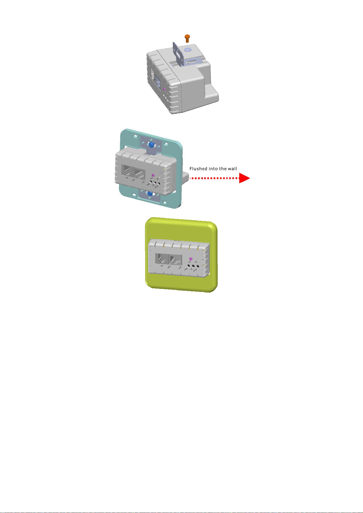
2 Installation
The followings are instructions for setting up the In Wall Access Point. Refer to the illustration and
follow the simple steps below to quickly install your In Wall Access Point.
Step 1:Slide the Bracket to align with screw holes on the HD28650, and fasten the Bracket tightly with
screws on the HD28650.
In Wall Access Point
10
Step 2:Slide the HD28650 into the Bottom Faceplate and fasten tightly into the Bottom Faceplate until
it’s flushed into the wall.
Step 3:Line-up and push the Top faceplate onto Bottom faceplate until snaps securely into place.
2-1 Installation Requirements
Before installing the In Wall Access Point, make sure your network meets the following
requirements.
System Requirements

In Wall Access Point 11
The In Wall Box Access Pointrequires one of the following types of software:
Windows 98 Second Edition/NT/2000/XP
Red Hat Linux 7.3 or later version
MAC OS X 10.2.4 or later version
Any TCP/IP-enabled systems like Mac OS and UNIX (TCP/IP protocol installed)
Standard phone line for xDSL modem
Or
Coaxial cable for Cable modem
Web Browser Software (Microsoft I.E 5.0 or later version or Netscape Navigator 5.0 or later
version)
One computer with an installed 10Mbps, 100Mbps or 10/100Mbps Ethernet card
UTP network Cable with a RJ-45 connection (Package contents)
Note: Prepare twisted-pair cables with RJ-45 plugs. Use Cat.5 cable for all connections. Make sure
each cable not exceed 328 feet (Approximately 100 meters).

In Wall Access Point
12
2-2 Getting Start
HD28650 support web-based configuration. Upon the completion of hardware installation, can be
configured through PC/NB by web browser such as Internet Explorer, Firefox, and Opera.
Default IP Address:10.59.1.254
Default Subnet Mask:255.255.255.0
Default Username and Password: admin/admin
Note
:
Set the IP segment of the administrator’s computer to be in the same range as HD28650 for
accessing the system. Do not duplicate the IP address used here with IP address of HD28650 or
any other device within the network.
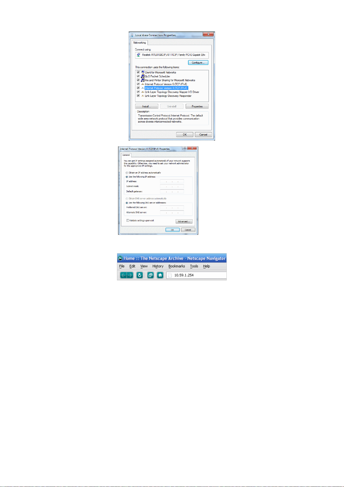
Step1:Click StartSettingControl Panel, and then “Control Panel” window appears, Click on
“Network connection” window appears.
Step2:In “Local Area Connection properties” window, select “Internet Protocol (TCP/IPv4)” and
click on “properties” button.
In Wall Access Point 13
Step 3:Launch your browser, and then enter the factory default IP address 10.59.1.254 in your
browser’s location box. Press Enter.
Step 4:.The HD28650 login screen will appear. In the Username and Password field, type the factory
default user name admin and password admin and click Setup. The HD28650 setup screen will
appear.
Example:
IP Address:10.59.1.109
Subnet Mask:255.255.255.0

In Wall Access Point
14
Note: It is important to remember your password. If for any reason you lose or forget your password, press the reset
button located on the top of the device. Reset action will re-initialize the settings. All configurations, including
username, password and IP address(s), will be reset, and requires re-entering.
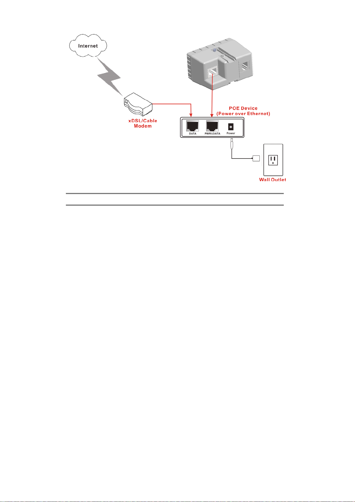
POE (Power over Ethernet) Application
HD28650
In Wall Access Point 15
Note: To use the HD28650’s POE feature, follow the instructions for your specific POE device.

In Wall Access Point
16
3 Configuring the In Wall Access Point
Step 1: Start your browser, and then enter the factory default IP address 10.59.1.254 in your browser’s
location box. Press Enter.
Figure 4 Web Browser Location Field (Factory Default)
Step 2: The In Wall Box Access Pointconfiguration tools menu will appear. In the Username and
Password field, type the factory default user name admin and password admin and click
Login. If you are first time setting the system, the wizard setup screen will appear. You will be
guided, step-by-step, through a basic setup procedure.
Figure 5 Configuration Tools Menu
Note:
This Web agent is best viewed with IE 5.0 or Netscape 6.0 and above browsers.
Username and Password can consist of up to 20 alphanumeric characters and are case sensitive.
If for some reason your password is lost or you cannot gain access to the In Wall Box Access
PointConfiguration Program, please press the reset button to load the device to manufacturer
defaults.
If the In Wall Box Access Pointdoesn’t send packet in 5 minutes (default), the In Wall Box Access
Pointwills logout automatically.
Proxy needs to set disable first when administrator accesses admin UI
Username: admin
Password: admin
HD28650

In Wall Access Point 17
The Setting enables you to configure advanced settings related to accessing the Internet;display In
Wall Box Access Pointbasic status and process Firmware upgrade, change password and backup or
restore configuration. Including,
Internet Setting
Link
Wireless
Basic
Advanced
Security
WPS
Administration
Management
Firmware
Configuration
SNMP
System Status
Ping Command
System Tool
Restart
Logout
Figure 6 Configuration Tools Menu

In Wall Access Point
18
3-1 Internet Setting
3-1-1 TCP/IP Setting
The IP address can be manually set or automatically assigned by a DHCP server on the LAN. If you are
manually setting the IP address, Subnet mask, and Gateway IP address settings, set them
appropriately, so that they comply with your LAN environment.
Figure 7 the TCP/IP Setting
DHCP Client
The device can work as a DHCP client. This allows the device to obtain the IP address and other
TCP/IP settings from your switch or IP router. If your device comes with this feature, please enable
Use DHCP Client.
Figure 8 DHCP Client Setting Screen
Item Default Description
MTU Setting 1492 MTU (Maximum Transfer Unit) specifies maximum

In Wall Access Point 19
transmission unit size.
Static IP
Figure 9 Static IP Setting Screen
Item Description
IP Address 10.59.1.254 Enter the IP address for the xDSL/Cable connection (provided
by your ISP).
Subnet Mask 255.255.255.0 Enter the subnet mask for the IP address.
Gateway IP
Gateway
Enter the Gateway IP address for the xDSL/Cable connection
Primary DNS
Server
A primary DNS server IP address for the xDSL/Cable
connection
Secondary
DNS Server
A secondary DNS server IP address for the xDSL/Cable
connection. If the primary DNS Server IP were not available,
meanwhile, Secondary DNS Server IP would start in the same
time.
MTU Setting 1492 MTU (Maximum Transfer Unit) specifies maximum
transmission unit size.

In Wall Access Point
20
3-2 Wireless
3-2-1 Wireless Basic Setting
Figure 10 Wireless Basic Setting Screen
Item Default Description
General Settings
ESSID Wireless The ESSID is the unique name that is shared among all
points in a wireless network. It is case sensitive and must not
exceed 32 characters.
Channel 6 Select the channel ID for wireless connection.
802.11 Mode 802.11g+802.11b
Select the 802.11 mode of following::
-802.11n+802.11g+802.11b
-802.11n+802.11g
-802.11g+802.11n
-802.11n only
-802.11g only
-802.11b only
Channel Width Auto 20/40MHz Select of channel width of Auto 20/40 MHz or 20MHz
Transmit Power 10% To Adjust the output power of the system to get the
appropriate coverage of your wireless network. Select the
10% to 100% that you needed for your environment.
Table of contents


