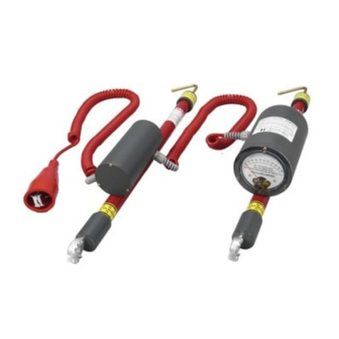
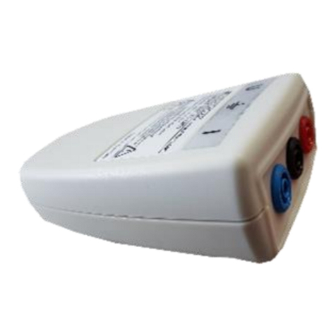
HDE DigiVolt DVM-80UVM Instruction Manual

Operating
and
Instruction
Manual
DV -80UV VOLT ETER/PHASER
a n d A C C E S S O R I E S
1475 Lakeside Drive • Waukegan, Illinois 60085 U.S.A. • 847.473.4980
f a x 8 4 7 . 4 7 3 . 4 9 8 1 • website: www.HDElectric C o m p a ny. c o m

2

IMPORTANT SAFETY INFORMATION . . . . . . . . . . . . . . . . . . . . . . . . . . . . . . . . . . . 4
ENERAL DESCRIPTION . . . . . . . . . . . . . . . . . . . . . . . . . . . . . . . . . . . . . . . . . . . . . 5
TECHNICAL SPECIFICATIONS . . . . . . . . . . . . . . . . . . . . . . . . . . . . . . . . . . . . . . . . . 6
OPERATIN INSTRUCTIONS . . . . . . . . . . . . . . . . . . . . . . . . . . . . . . . . . . . . . . . . . 7-9
Pre-Use Inspection . . . . . . . . . . . . . . . . . . . . . . . . . . . . . . . . . . . . . . . . . . . . . . . 7
Voltage and Phasing Measurements – Line-to-Line . . . . . . . . . . . . . . . . . . . . . 7
Voltage Measurements – Line-to- round . . . . . . . . . . . . . . . . . . . . . . . . . . . . . 8
Test Point Measurements . . . . . . . . . . . . . . . . . . . . . . . . . . . . . . . . . . . . . . . . . 8
Peak Hold . . . . . . . . . . . . . . . . . . . . . . . . . . . . . . . . . . . . . . . . . . . . . . . . . . . . . . 9
Care and Maintenance . . . . . . . . . . . . . . . . . . . . . . . . . . . . . . . . . . . . . . . . . . . . 9
PROBES AND ACCESSORIES . . . . . . . . . . . . . . . . . . . . . . . . . . . . . . . . . . . . . . 9-14
Overhead and Underground Probes . . . . . . . . . . . . . . . . . . . . . . . . . . . . . . . . . 9
Add-on Resistor Stick . . . . . . . . . . . . . . . . . . . . . . . . . . . . . . . . . . . . . . . . . . . . 10
Hot Stick . . . . . . . . . . . . . . . . . . . . . . . . . . . . . . . . . . . . . . . . . . . . . . . . . . . . . . 10
Hot Stick Adapter . . . . . . . . . . . . . . . . . . . . . . . . . . . . . . . . . . . . . . . . . . . . . . . 10
Proof Tester®Voltmeter Tester . . . . . . . . . . . . . . . . . . . . . . . . . . . . . . . . . . . . 11
Cable Fault Tester . . . . . . . . . . . . . . . . . . . . . . . . . . . . . . . . . . . . . . . . . . . . 12-14
REPAIRS . . . . . . . . . . . . . . . . . . . . . . . . . . . . . . . . . . . . . . . . . . . . . . . . . . . . . . . . . . 14
CALIBRATION AND MAINTENANCE LO . . . . . . . . . . . . . . . . . . . . . . . . . . . . . . . 15
TERMS AND CONDITIONS OF SALE . . . . . . . . . . . . . . . . . . . . . . . . . . . . . . . . . . 16
3
Operating & Instruction Manual
DVM-80UVM
a n d AC C E S S O R I E S
VOLT ETER/PHASER

4
All meters require the use of accessory hot sticks, which may or may not be supplied with
the meter. The minimum hot stick length required for safe use depends upon the particular
operation; consult federal, state, company and OSHA specifications for the proper hot
stick length for the intended operation.
The users of this meter should always be equipped with personal protective equipment
including high voltage gloves, flame retardant clothing, eye and face protection. Some
applications may require additional protective equipment.
Accessory probes are available for all meters. Always use the proper probe(s) for
your application.
OPERATIONAL IMPAIRMENT - If the DVM is used in a manner not described in this
instruction manual, the protection and effective operation of this equipment may be impaired.
Failure to follow these and other warnings and safety precautions may result in
severe injury or death.
WARNING
WARNING
HOT STICK REQUIRED
DANGER
Keep Connecting Cord
Free and Clear of Everything
At All Times During Operation.
#VMCWL-96
See Instructions
DANGER
ELECTRIC SHOCK HAZARD
ELECTRICAL ARC HAZARD
READ INSTRUCTIONS AND OPERATIONS
MANUAL BEFORE USE
Always wear personal protectve equ pment nclud ng eye and face
protect on, nsulatng gloves and FR cloth ng.
All OSHA and company work pract ces must be followed.
Always ma nta n proper work ng clearances.
Use only HD Electr c probes appropr ate and ntended for the work
to be performed.
Th s product s des gned for use by profess onals tra ned n ts use
and applcat on n and around h gh voltage electr cal equpment. If
you are not tra ned n the work methods requred for safe operaton,
DO NOT PROCEED unt l you obta n the proper tra n ng.
Fa lure to follow these recommended practces may result n severe
burns, serous njury or death.
HD Electr c Company
www.hdelectr ccompany.com Phone: (847) 473-4980
IMPORTANT SAFETY INFORMATION
Read and understand these instructions prior to use. These operating instructions
are not a substitute for proper training in the use of this equipment. High voltage
systems present serious hazards, including the risk of death or serious injury due to arcing,
thermal burns and electrocution. HD Electric Company products are intended solely
for use by professionals with knowledge, training and experience in the use of the
equipment and its accessories in and around high voltage systems.
All applicable federal, state, company and OSHA work practices must be followed. If you
are unfamiliar with the work practices required, DO NOT PROCEED. Call HD Electric
Company if you have any questions regarding this equipment. These important labels
are affixed to the product. Read and understand each label before proceeding.
THESE I PORTANT LABELS ARE AFFIXED TO THE PRODUCT.
READ AND UNDERSTAND EACH OF THE BEFORE PROCEEDING.
To measure elbow test points, push ON button again. Blinking single decimal
point indicates test point measurement mode. Meter displays actual primary voltage.
To measure direct contact, push ON button again.
PEAK HOLD mode is indicated by two additional flashing decimal points. To clear
PEAK HOLD reading, press PEAK HOLD button again.
Rigorous hot stick work precautions and all OSHA and company work
NOTICE: Use only with insulated hot sticks with length appropriate for voltage and use
correct probes for overhead and underground applications. This product is designed for use
by professionals trained in its use and application in and around high voltage electric equipment.
If you are not trained in the work methods required for safe operation, do not proceed until you
obtain the training.
Do not rely on elbow test point measurements for indication that circuit is deenergized. Do
not exceed 40kV without extension resistors. Install one R-80 extension resistor on each stick for readings
to 80kV and multiply display reading x 2. Meter display 1.indicates overrange. Test on known voltage
source before and after each use. Inspect connecting cord and return meter to HD Electric Company
for repair if cord or other meter components are worn or damaged. Keep connecting cord free and
clear of all energized and grounded surfaces during application.
WARNING:
practices must be followed. Always wear approved insulated gloves, eye and face
protection and FR clothing. Do not touch meter housing during measurement.
Read and understand instructions prior to use. Failure to follow these instructions
or other misuse or misapplication can lead to severe injury and death.
Replace battery with 9V Alkaline or Lithium only
Part No. DVM-80UVM
www.HDElectricCompany.com 01/19
DigiVolt 80UVM
®
Serial No.
CAUTION:

5
ENERAL DESCRIPTION
The DVM-80UVM is a high accuracy digital voltmeter and phasing set designed to measure
voltages up to 40kV and up to 80kV when used with a pair of add-on resistors. The
DVM-80UVM includes an elbow test point reading feature as well as a peak hold
feature. The DVM-80UVM can be purchased on its own or in a complete, ready-
to-use Universal Voltmeter Kit that contains the following probes and accessories:
DVM-80UVK UNIVERSAL VOLTMETER KIT
• Dual stick phasing voltmeter (DVM-80UVM)
• Two overhead hook probes (025-OLPS-5)
• Two resistor sticks for measurements up to 80kV (R-80)
• Two underground bushing probes, 15 and 25kV class (ASP-15/25)
• An underground cable fault tester, 15, 25 and 35kV class (CFT-35)
• Voltmeter proof tester (PT-5000B)
• Two shotgun hot stick adapters (HSA-2500)
• A soft-sided, multi-functional carrying bag (B-12)
See pages 9-14 for a complete list of probes and accessories available.
All HD Electric voltmeters and phasers are constructed with epoxy encapsulated high
voltage resistors, a connecting cord and a meter display. The DVM-80UVM is a digital
meter. The major elements are shown here:
The high voltage resistors limit the current through the connecting cord to less than one
milliamp. Although the connecting cord is insulated for voltage up to 10kV, it should
always be kept free and clear from you, ground and any other conductors. These
instruments will measure DC and AC 16-1000Hz RMS.
WARNING: The DVM-80UVM will require add-on resistor sticks for higher voltage
ranges. Always completely remove the voltmeter from the live circuit before adding
or removing add-on resistor sticks. Always use add-on resistor sticks in pairs, one on
each voltmeter stick.
Universal Spline
Resistor
Stick
Resistor Stick
Universal Spline
Connecting
Cord
LCD Screen

6
TECHNICAL SPECIFICATIONS
ENVIRONMENTAL CONDITIONS
• Conditions
-
Indoor and outdoor use
• Altitude
-
Up to 6,566 ft. (2000M)
• Operating -20°F to +140°F
Temperature
-
(-29°C to +60°C)
• Humidity
-
95% to +60°C
(non-condensing)
• Pollution Degree
-
PD4
• easurement Category IV
-
Classification Rating (CAT IV) –
Product is intended for use with test
and measuring circuits connected to
the circuits/wiring outside of a building
installation, including transmission lines.
• Overvoltage Category IV
• Enclosure aterial
-
PVC UL 94-V0, fiberglass
• Printed Circuit Boards
-
FR-4 UL94V-0
BATTERY REPLACEMENT
INSTRUCTIONS
To replace the battery, open and remove
the compartment on the rear of the
meter housing. Remove and dispose
of the old battery, replacing it with a
fresh, new 9-volt lithium or alkaline
battery. Note battery polarity on
the battery compartment. This
compartment cannot be reinserted
if the battery polarity is reversed.
MANUFACTURIN LOCATION
HD Electric Company • Waukegan, IL. 60085, USA
DIMENSIONS:
• Length (w/o probes)
-
15.125” (38.4cm)
• Display Housing
-
5”W x 4.5”L x 1.38”H
(13cm x 11cm x 3.5cm)
• Diameter of Fiberglass
-
1” (2.54cm)
• Connecting Cord Length
-
12’ (3.6m) fully extended,
3.5’ (1.7m) retracted
• Weight
-
(w/o probes): 3.0 lbs. (1.36kg)
• LCD Numeral Height
-
0.4”, indicates 3.5 digits
• Battery Life
-
17 hours continuous use
• Battery
-
9V alkaline 1604A, IEC 6LR61
or 9V lithium, ANSI-1604LC.
• Digital eter
-
Reads in kilovolts,
3.5 digits with decimal point
• Voltage Range
-
5V-40kV, up to 80kV
with add-on resistors, DC, AC 16-1000Hz
• Auto-Ranging
-
No range selector switch
• Accuracy
- Within 1% of reading +/- 3 counts
- With R-80 add-on resistors installed -
within 2% of reading +/- 3 counts
(line-to-ground & line-to-line measurements)
• eter Resolution
0.005 - 1.899 range with 1 Volt resolution
1.90 - 18.99 range with 10 Volt resolution
19.0 - 40.0 range with 100 Volt resolution

7
OPERATIN INSTRUCTIONS
The DVM-80UVM requires one 9V lithium or alkaline battery, which powers
the unit and activates the backlight. The meter will shut off automatically a
few minutes after the display reads zero, but not while voltage measurements
are being made. The DVM-80UVM includes an elbow test point reading feature,
which is displayed by a blinking decimal point ( . ) and a Peak Hold feature which
is indicated by all decimal points flashing.
To activate the Peak Hold feature, press the Peak Hold button. The display will hold
the highest reading while Peak Hold is activated. To deactivate the Peak Hold and
clear the display, press the Peak Hold button again.
NOTE: The meter will not shut off while a peak reading is displayed.
The backlight is always on when the unit is powered on. The low battery feature will
simply shut off or will not turn on the meter when the battery is low. The unit has a 0.4”
LCD display that indicates 3-1/2 digits. The DVM-80UVM measures RMS AC and DC.
To take readings above 40kV, attach one R-80 resistor stick on each meter stick,
and then multiply the reading on the display by two (for example, if the display
reads 30kV with add-on resistor sticks installed, multiply 30 times 2 = 60.0kV).
Do not exceed 80kV with the R-80 resistor sticks attached.
PRE-USE INSPECTION
WARNING: Before using the instrument be sure to test and inspect the equipment
to ensure that it is functioning properly and is in safe, working condition. Failure to do
so may cause serious injury or death and may result in erroneous test measurements.
Before making any high voltage measurements, test and inspect the
voltmeter/phaser as follows:
1) Make certain the instrument is clean, dry and waxed to a clear shiny surface.
2) Inspect the cord for cracked insulation.
3) Be sure that you are using hot sticks of the appropriate length, and examine each
hot stick to ensure that it is clean, dry and waxed to a clear shiny surface.
4) Attach the appropriate probes for overhead or underground applications (see page 9)
and ensure that the probes are properly installed and tightened (do not overtighten).
5) Install add-on resistor sticks if necessary for the range being tested.
6) Test the voltmeter/phaser with a proof tester such as the HD Electric PT-5000B
Proof Tester Voltmeter Tester (see page 10).
Voltage and Phasing Measurements – Line-to-Line
We recommend that two person crews perform all line-to-line voltage measurements
and phasing operations. Since the operation is occurring near two energized conductors,

8
OPERATIN INSTRUCTIONS continued
the use of two person crews allows each person to operate one meter stick and maintain
high safety standards.
In order to make line-to-line measurements, each probe must contact an energized line.
Be sure that only those probes intended for the particular application are used (see page
9). Always keep the connecting cord free and clear of energized phases and ground.
For phasing applications, the probes will be placed on opposite sides of an open point,
typically a switch. The phasing operation will indicate if two sides of a line are in-phase
before closing a switch.
To check all phases, proceed as follows:
1) Measure voltage on each phase from line-to-ground to verify all phases are
live and at the same voltage.
2) Place one of the probes on a conductor on one side of the switch.
3) Place the other probe on one of the three phases on the other side of the switch.
4) If the conductors are out-of-phase, the meter will read line-to-line voltage.
If they are in-phase, the meter will read near zero but may read up to 15% of
the line-to-line voltage.
5) Continue this procedure with all three phases on both sides of the switch.
If an intermediate reading is found, the phasing cannot be determined by this
method and the switch should not be closed until other means are used for phasing.
Voltage Measurements – Line-to-Ground
Keep the connecting cord free and clear while testing.
To use this two-stick voltmeter/phaser, first connect one of the probes to either
a ground or system neutral making sure the resistor stick is making contact at all
times during measurement. The other probe should be connected to the energized
source to be measured.
Maintain contact only long enough to read the meter. Always remove the probe
from the energized source first before removing the ground connection.
TEST POINT EASURE ENTS
The DVM-80UVM includes a Test Point feature for measuring voltage from elbow test
points. To activate Test Point mode simply push the ON button again. Test Point mode
is indicated by a blinking decimal point. To turn Test Point mode off, simply push the ON
button once again and the decimal point will stop blinking. When using a voltmeter/phasing
set to phase between test points, the important measurement is whether high voltage is
present or not. The proper procedure for phasing between elbow test points is as follows:
1) Both elbows must be energized. Follow the proper safety practices for removing
the test point protective caps and exposing the live test points. Treat all exposed
electrodes as energized high voltage. Measure from both elbow test points to
ground. These measurements should show that both elbows are energized and,
if both elbows are of the same type and manufacture, should measure the
approximate line voltage.

9
OPERATIN INSTRUCTIONS continued
2) Measure from one elbow test point to the other. This reading will show either a
high voltage reading indicating the elbows are out-of-phase or a zero or low voltage
reading indicating the elbows are connected to the same phase. The out-of-
phase measurement will likely not show the higher voltage expected from
a phase-to-phase measurement but will be closer to the line-to-ground
voltage. The in-phase voltage measurement can be between zero and 15%
of the nominal line-to-ground voltage. If both elbows are of different type and
manufacture, then a higher reading may occur.
PEAK HOLD
The DVM-80UVM includes a Peak Hold feature. To activate the Peak Hold feature
press the Peak Hold button. Peak Hold is indicated by all decimal points flashing.
The display will hold the highest reading while Peak Hold is activated. To deactivate
the Peak Hold and clear the display, press the Peak Hold button again.
Note: The meter will not shut off while a peak reading is displayed.
CARE AND AINTENANCE
Periodic regular maintenance is required to keep the voltmeter in proper operating condition.
Keep the voltmeter clean and dry and always store it in its case. The fiberglass sticks
should be kept clean and free of dirt, contamination and marking. Examine the cord for
cracking or other damage prior to each use. Although we don’t specify a calibration cycle,
we recommend you test, measure and calibrate your instrument annually. The Calibration
and Maintenance Log provided on page 15 can be used to record these events.
Contact HD Electric Company for details.
CLEANING INSTRUCTIONS: To clean the DVM-80UVM wipe with a damp cloth with water.
Do not use harsh chemicals or solvents.
PROBES AND ACCESSORIES
WARNING: ALWAYS use probes appropriate to your application. NEVER use overhead
probes in underground applications. Failure to use the correct probe can result in arcing
or electrical contact and may cause serious injury or death. If you are not trained in the
particular operation or are not sure about the appropriate probe for your application
DO NOT PROCEED.
The DVM-80UVM comes standard with two overhead hook probes (025-OLPS-5), a
9-volt battery, instruction manual and a carrying case (CS-DVM). The DVM-80UVK
Universal Voltmeter Kit is supplied with a DVM-80UVM dual stick phasing voltmeter, two
overhead hook probes (025-OLPS-5), two resistor sticks (R-80), two underground bushing
probes (ASP-15/25), an underground cable fault tester (CFT-35), voltmeter proof tester
(PT-5000B), two shotgun hot stick adapters (HSA-2500), a 9-volt battery, instruction
manual and a soft-sided carrying bag (B-12). The following pages describes these probes
as well as other optional probes and accessories available.

10
PROBES AND ACCESSORIES continued
OVERHEAD PROBES
• 025-OLPS-5 brass hook probe
• 025-OLPS-6 brass pigtail probe
UNDERGROUND
DEAD FRONT
BUSHING PROBES
• ASP-15/25 for use in 15kV and 25kV
loadbreak bushings
• ASP-35U for use in 35kV
loadbreak bushings
UNDERGROUND
ELBOW PROBE
EA-15/25 for insertion in loadbreak elbows
NOTE: The elbow must be firmly
supported when using this probe
INSULATED
UNDERGROUND
PROBE
CP-1 for general underground use
on grounded terminals, exposed high
voltage terminals or elbow test points.
ADD-ON RESISTOR STICK
R-80 Resistor Sticks are used to take readings above 40kV. Always
completely remove the voltmeter from the live circuit before adding
or removing add-on resistor sticks. Always use the add-on
resistor sticks in pairs, one on each voltmeter stick, then
attach the appropriate overhead or underground probe
to be used. When a reading is displayed, multiply that
reading by two (for example, if the display reads 30kV
with add-on resistor sticks installed, multiply
30 times 2 = 60kV). Do not exceed 80kV
with the R-80 resistor sticks attached.
HOT STICK
A range of hot sticks are available
in lengths starting at 4’. Contact
HD Electric for more details.
HOT STICK ADAPTER
HSA-2500 shotgun
hot stick adapter
ASP-15/25 EA-15/25ASP-35U
025-OLPS-6025-OLPS-5
GCP-1
HSA-2500
R-80
Hot Stick

11
PROOF TESTER®
VOLT ETER TESTER
The PT-5000B Proof Tester
Voltmeter Tester will produce
5kVDC at the test leads to
confirm proper operation of
voltmeters and phasers. This
tester should be used only with
voltmeters/phasers that measure
DC voltage. It will not confirm
operation of voltmeters/
phasers that measure AC
voltage only. The PT-5000B
operates from one 9V lithium
or alkaline battery and
produces approximately
5kVDC at the connecting
leads. To use:
1) Connect both tester leads
to the voltmeter/
phaser probes.
2) Press and hold both
TEST buttons.
3) Confirm a good battery
by checking the red light
on the Tester. If the red light
does not come on, replace
the battery with a 9V lithium or alkaline only.
4) Verify the voltmeter/phaser reads approximately 5kV.
5) Release the TEST buttons and disconnect the Tester from the voltmeter/phaser.
WARNING: Do not use the voltmeter/phaser if proper operation is not confirmed.
WARNING: Do not use this tester except as directed. Do not use to test equipment
other than voltmeters/phasers. Do not apply to energized circuits or equipment. Refer
all servicing to the factory. Failure to follow these instructions may lead to electric
shock, severe injury or death.
PT-5000B Proof Tester
Voltmeter Tester
PROBES AND ACCESSORIES continued

12
CABLE FAULT TESTER
The CFT-35 Cable Fault Tester is for
use only with two stick voltmeters
for testing leakage
current in underground
primary voltage cables.
The CFT-35 can be used
on underground cables with grounded neutrals with a maximum line-to-ground voltage of
21.1kV or maximum line-to-line voltage of 36.6kV. Operation at higher voltages may
damage the CFT-35 and provide erroneous test results.
The CFT-35 is used with a voltmeter/phaser for testing installed or repaired underground
cable prior to energizing it. Only cable with extruded dielectric such as rubber or polyethylene
can be tested with the CFT-35. Using the CFT-35 on paper insulated cable may provide
erroneous test results caused by higher leakage currents typical for this type of cable.
The CFT-35 contains a high voltage rectifier and is connected to test underground
primary cable as shown in this circuit:
In practice, the CFT-35 rectifies the high voltage from the source, usually a transformer
primary, and charges up the cable, shown as a capacitor above. When a connection is
first made, the DC from the CFT-35 will charge up the cable capacitance through the
resistors in the meter sticks. If the cable is good, current will stop flowing when the
cable is charged up. If the cable is not good, the cable will not charge and current will
continue to flow, as indicated by a higher meter indication.
The following equipment is required for testing cable with a CFT-35:
1) An HD Electric two-stick voltmeter/phaser.
2) The CFT-35 Cable Fault Tester.
3) For deadfront applications, ASP bushing probe(s) or, for live front
applications, CP-1 probe(s). An EA-15/25 elbow probe may also
be used for deadfront applications.
4) For deadfront applications, a feed-through bushing may also be used.
PROBES AND ACCESSORIES continued
CFT-35

13
PROBES AND ACCESSORIES continued
Shown here is a typical application
of the CFT-35 and associated equipment
for testing underground cable from
a pad-mount dead front transformer:
Before using the
CFT-35, read and
understand all of
the instructions and
precautions for live
testing with voltmeters/phasers
(pages 7 & 8). In addition, be
sure to consult your company’s work
practices and any information provided
by the manufacturers of the apparatus
that you are testing.
Testing using the CFT-35 should
be performed as follows:
1)Test the cable with the HDE voltmeter/phaser to ensure
that it is not energized and that it is discharged.
2)Ensure that the cable to be tested is completely
isolated; that both ends have no other connection
to voltage or to a transformer winding
and are properly terminated.
3)Assemble the CFT-35
with appropriate
probe on the
voltmeter/phaser
stick with the meter.
4)Assemble the appropriate probe on the voltmeter/phaser stick without the meter.
5)Connect the voltmeter/phaser stick without the meter to the cable to be tested.
5)Connect the voltmeter/phaser stick with the CFT-35 to the voltage source.
6)Read the display on the voltmeter/phaser. The reading will be initially high.
For a short cable, the reading should return quickly to near zero.
For a longer cable, it may take a few seconds for the reading to return to near zero.
8)If the reading does not return to near zero after several seconds, the cable is
leaking or shorted and the test should be discontinued. Remember that all HDE
voltmeters/phasers are intermittent duty devices and should be connected only as
long as necessary to obtain a reading.
9)Discharge the cable by removing the voltmeter/phaser from the line, removing
the CFT-35 from the voltmeter/phaser and connecting the voltmeter/phaser from
cable to ground.
Cable Fault Tester
and Bushing Probe

14
PROBES AND ACCESSORIES continued
With the DVM-80UVM, if the cable is completely shorted the meter will read the line
voltage times 0.71. For a nominal 7.2kV circuit the meter will read approximately 5.1kV.
Listed here are the actual cable leakage currents for voltage readings on the
DVM-80UVM digital meter: Meter reading of 0.5kV = 8uA
Meter reading of 1.0kV = 16uA
Meter reading of 2.0kV = 31uA
REPAIRS
All repairs and calibration are performed at HD Electric Company.
If any damage is found, please contact HD Electric Company at
847-473-4980 or saleshde@emerson.com to arrange for service.

CALIBRATION AND AINTENANCE LOG
DATE CALIBRATED BY
15

TER S AND CONDITIONS OF SALE
HD Electric Company is herein referred to either as “HDE” or “Seller” and the customer or person or entity purchasing goods or services (hereinafter collectively referred to as “ oods”) is referred to as the “Buyer”. These
Terms and Conditions, any price list or schedule, quotation, acknowledgment or invoice from HDE relevant to the sale of the oods and all documents incorporated by specific reference therein, constitute the complete and
exclusive statement of the terms of the agreement governing the sale of oods by HDE to Buyer. Buyer’s acceptance of the oods will manifest Buyer’s assent to these terms and conditions without variation or addition. Any
different or additional terms in Buyer’s purchase order or other Buyer documents are hereby objected to. HDE reserves the right in its sole discretion to refuse orders.
1. PRICES AND TAXES: Unless a fixed price is quoted, the price at which this order is accepted is subject to adjustment to HDE’s price in effect at the time of order. Any current or future tax or governmental charge (or in-
crease in same) affecting Seller’s costs or production, sale or delivery or which Seller is otherwise required to pay or collect in connection with the sale, purchase, delivery, storage, processing, use or consumption of oods
(but excluding any tax on Seller’s net income or profit) shall be for Buyer’s account and shall be added to the price.
2. TER S OF PAY ENT: Terms are stated on HDE’s invoice in U.S. currency. HDE shall have the right, among other remedies, either to terminate this agreement or to suspend further performance under this and/or other
agreements with the Buyer in the event Buyer fails to make any payment when due, which other agreements Buyer and Seller hereby amend accordingly, or HDE otherwise deems itself insecure. Buyer shall be liable for all
expenses, including attorneys’ fees, relating to the collection of past due amounts. Should Buyer’s financial responsibility become unsatisfactory to HDE, cash payments or security satisfactory to HDE may be required by
HDE for future deliveries and for the goods theretofore delivered. If such cash payment or security is not provided, in addition to HDE’s other rights and remedies, HDE may discontinue deliveries. HDE may apply a finance
charge for payments made by credit card.
3. SHIP ENT AND DELIVERY: Unless otherwise expressly provided, shipments are made F.O.B. HDE’s shipping point. Risk of loss or damage and responsibility shall pass from HDE to Buyer upon delivery to and receipt
by common carrier. Any claims for shortages or damages suffered in transit are the responsibility of Buyer and shall be submitted by the Buyer directly to the carrier. Shortages or damages must be acknowledged and signed
for at the time of delivery. While HDE will use all reasonable commercial efforts to maintain the delivery date(s) acknowledged or quoted by HDE, all shipping dates are approximate and not guaranteed. HDE reserves the
right to make partial shipments. HDE, at its option, shall not be bound to tender delivery of any oods for which Buyer has not provided shipping instructions. If the shipment of the oods is postponed or delayed by Buyer for
any reason, Buyer agrees to reimburse HDE for any and all handling and storage costs and other additional expenses resulting therefrom. All claims for shipping errors, lost shipments or any other discrepancies must be
made within ninety (90) days or they will be disallowed and deemed waived.
4. HDE LI ITED WARRANTY: HDE covers its products with a manufacturer’s warranty against defects in material or workmanship for a period of ten years in the case of Capacitor Controls and in all other circumstances
for a period of one year, unless otherwise stated by HDE in writing. To take advantage of this warranty, the complete product must be delivered prepaid to HDE or any HDE Authorized Service Center. This warranty shall not
apply to any oods including but not limited to products which: (a) Have been repaired or altered outside HDE’s factory (or Authorized Service Center) or in any manner so as, in HDE’s judgment, to affect its serviceability or
proper operation; (b) Have been subjected by persons other than HDE (or Authorized Service Center) to improper handling, operation, maintenance, repair or alteration; and, (c) Have been subjected to normal wear and tear,
misuse, negligence, improper installation or accident. HDE’s obligation under this warranty, and the Buyer’s exclusive remedy for the breach thereof, shall be limited to, at HDE’s option, repair or replacement of any allegedly
defective oods or issuance of credit. HDE requires the return of any allegedly defective oods, transportation prepaid, before honoring any claim. All returned oods are subject to inspection, and if examination does not
disclose any defect covered by this warranty, replacement of such oods or issuance of credit for same will not be approved.
THE FORE OIN CONSTITUTES HDE’S SOLE WARRANTY RESPONSIBILITY AND BUYER’S EXCLUSIVE REMEDY WHETHER SOUNDIN IN TORT, CONTRACT, STRICT LIABILITY OR OTHERWISE, EXCEPT
AS OTHERWISE EXPRESSLY SET FORTH IN THIS A REEMENT. THERE ARE NO OTHER WARRANTIES, EXPRESS OR IMPLIED, WHETHER OF MERCHANTABILITY, FITNESS FOR A PARTICULAR PURPOSE,
OR OTHERWISE. No employee, agent, dealer, or other person is authorized to give any warranty on behalf of HDE. This warranty extends only to persons or organizations who purchase the oods from HDE for resale.
5. LI ITATION OF RE EDY AND LIABILITY: THE SOLE AND EXCLUSIVE RE EDY FOR BREACH OF ANY WARRANTY HEREUNDER SHALL BE LI ITED TO REPAIR, CORRECTION, REPLACE ENT OR CREDIT
UNDER SECTION 4. HDE SHALL NOT BE LIABLE FOR DA AGES CAUSED BY DELAY IN PERFOR ANCE, AND IN NO EVENT, REGARDLESS OF THE FOR OF THE CLAI OR CAUSE OF ACTION (WHETHER
BASED IN CONTRACT, INFRINGE ENT, NEGLIGENCE, STRICT LIABILITY, OTHER TORT OR OTHERWISE), SHALL HDE’S LIABILITY TO BUYER AND/OR ITS CUSTO ERS EXCEED THE PRICE PAID BY BUYER
FOR THE SPECIFIC GOODS GIVING RISE TO THE CLAI OR CAUSE OF ACTION, AND BUYER SHALL INDE NIFY HDE FOR ANY DA AGES IN EXCESS THEREOF. BUYER AGREES THAT IN NO EVENT
SHALL HDE’S LIABILITY TO BUYER AND/OR ITS CUSTO ERS INCLUDE SPECIAL, INDIRECT, INCIDENTAL, CONSEQUENTIAL OR PUNITIVE DA AGES OF ANY CHARACTER IN CONNECTION WITH THE
SALE, RESALE OR USE OF THE GOODS, WHICH ARE WAIVED BY BUYER AND AS TO WHICH BUYER SHALL INDE NIFY HDE. The term “consequential damages” shall include, but not be limited to, loss of an-
ticipated profits, business interruption, loss of use of revenue, cost of capital or loss of or damage to property, equipment, or data, or loss of reputation. Further, Buyer shall indemnify and hold HDE harmless from any liability
to Buyer, Buyer’s employees, workers, contractors or any other persons arising out of Buyer’s, and any other persons’, use of the oods. All instructions and warnings supplied by HDE will be passed on to those persons who
use the oods. HDE’s oods are to be used in their recommended applications and all warning labels adhered to the oods by HDE shall be left intact. It is impossible to eliminate all risks associated with the use of the
oods. Risks of serious injury or death, including risks associated with electrocution, arcing and thermal burns, are inherent in work in and around energized electrical systems. Such risks arise from the wide variety of elec-
trical systems and equipment to which oods may be applied, the manner of use or application, weather and environmental conditions or other unknown factors, all of which are beyond the control of HDE. HDE does not
agree to be an insurer of these risks, and shall have no liability for any claims arising from such risks. WHEN YOU BUY OR USE THESE PRODUCTS, YOU A REE TO ACCEPT THESE RISKS.
6. EXCUSE OF PERFOR ANCE (FORCE AJEURE): HDE shall not be liable for delays in performance or for non-performance due to acts of od; acts of Buyer; war; fire; flood; weather; sabotage; strikes, labor disputes,
civil disturbances or riots; governmental requests, restrictions, allocations, laws, regulations, orders or actions; unavailability of or delays in transportation; default of suppliers; or unforeseen circumstances or events beyond
HDE’s reasonable control. Deliveries or other performance may be suspended for an appropriate period or cancelled by HDE upon notice to Buyer in the event of any of the foregoing, but the balance of this agreement shall
otherwise remain unaffected. If HDE determines that its ability to supply the total demand for the oods, or to obtain material used directly or indirectly in the manufacture of the oods, is hindered, limited or made impracti-
cable due to causes set forth herein, HDE may allocate its available supply of the oods or such material (without obligation to acquire other supplies of any such oods or materials) among itself and its purchasers on such
basis as HDE determines to be equitable without liability for any failure of performance which may result therefrom.
7. CHANGES: HDE reserves the right to change designs and specifications for standard oods without prior notice to Buyer, but not with respect to custom oods being made for Buyer. HDE shall have no obligation to in-
stall or make such change in any oods manufactured prior to the date of such change.
8. ASSIGN ENT: Buyer shall not assign its rights or delegate its duties hereunder or any interest herein without the prior written consent of HDE, and any such assignment, without such consent, shall be void.
9. INSTALLATION: Buyer shall be responsible for receiving, inspecting, testing, storing, installing, starting up and maintaining all oods.
10. INSPECTION/TESTING: Buyer, at its expense, agrees that it will promptly inspect the oods upon receipt thereof, and in no event later than thirty (30) days from the date of receipt of the oods. Buyer shall deliver to
HDE within fifteen (15) days of inspection, but in no event later than forty-five (45) days from the date of receipt of the oods, written notice of any and all deficiencies, defects, variations from specifications or complaints of
any kind with respect to the quantity, quality, condition, shipment, performance, price or appearance of the oods so received by Buyer. In the event no such written notice is received by HDE, Buyer shall be deemed con-
clusively to have inspected and accepted all such oods unconditionally and to have waived any and all rights and claims, including without limitation any right to reject the oods or to claim damages in respect thereof. Buyer
may not return goods without first advising HDE of the reasons therefore, obtaining from HDE a material authorization number and observing such instructions as HDE may give in authorizing such return. In the event a re-
turn is authorized by HDE, a restocking for any oods requiring repackaging or maintenance a twenty percent (20%) restocking fee shall be assessed to Buyer in the final credit amount.
11. SERVICES: If this agreement requires HDE to perform or provide any services, HDE (including without limitation its successors, assigns, agents or any person or entity acting at HDE’s direction) shall not be responsible
for any damages, claims, liabilities or expenses of any nature arising out of such services.
12. U.S. EXPORT CONTROL LAWS: All oods sold to Buyer by HDE hereunder are subject to U.S. Export Control Laws. Buyer hereby agrees not to re-sell or divert any goods contrary to such laws.
13. CO PLIANCE: Seller/Contractor shall comply with all applicable federal, state or local laws, rules, regulations, or orders. Seller/Contractor shall comply with Executive Order 11246, as amended by Executive Order 11375,
and the applicable provisions of the Office of Federal Contract Compliance Programs (OFCCP), 41 CFR Part 60, which are incorporated herein by this reference. Buyer shall comply with all applicable federal, state, or local
laws, rules, regulations or orders including but not limited to the Foreign Corrupt Practices Act of 1977, as amended. HDE reserves the right to delay or refuse delivery if requests for reasonable assurances of Buyer’s com-
pliance are not tendered as requested.
14. ISCELLANEOUS: These terms and conditions supersede all other communications, negotiations and prior oral or written statements regarding the subject matter hereof. No change, modification, rescission, discharge,
abandonment, or waiver of these terms and conditions shall be binding upon HDE unless made in writing and signed on its behalf by its duly authorized representative. No conditions, usage or trade, course of dealing or per-
formance, understanding or agreement purporting to modify, vary, explain, or supplement these terms and conditions shall be binding unless hereafter made in writing and signed by Seller. No modification shall be effected
by HDE’s receipt or acceptance of Buyer’s purchase orders, shipping instruction forms, of other documentation containing terms at variance with or in addition to those set forth herein, all of which are objected to by HDE. Any
such modifications or additional terms are specifically rejected by HDE. No waiver by HDE with respect to any breach or default of any right or remedy and no course of dealing, shall be deemed to constitute a continuing
waiver of any other breach or default of any other right or remedy, unless such waiver be expressed in writing and signed by HDE. All typographical or clerical errors made by HDE in any quotation, acknowledgment or pub-
lication are subject to correction. Validity and performance relating to the interpretation and effect of this agreement shall be governed by the laws of the state of Illinois without regard to its conflict of law principles.
15. DISPUTE RESOLUTION: In the event of any dispute INCLUDIN , BUT NOT LIMITED TO, BREACH OF CONTRACT, BREACH OF WARRANTY, CLAIMS BASED IN TORT, NE LI ENCE, PRODUCT LIABILITY,
FRAUD, MARKETIN , STATE OR FEDERAL RE ULATIONS, ANY CLAIMS RE ARDIN THE ENFORCEABILITY OF THIS LIMITED WARRANTY, AND THE WAIVER OF CLASS ACTION TRIALS between Buyer and
Seller, either may choose to resolve the dispute by binding arbitration, as described below, instead of in court. THIS MEANS IF EITHER BUYER OR SELLER CHOOSE BINDIN ARBITRATION, NEITHER PARTY SHALL
HAVE THE RI HT TO LITI ATE SUCH CLAIM IN COURT OR HAVE A JURY TRIAL. DISCOVERY AND APPEAL RI HTS ARE LIMITED IN BINDIN ARBITRATION. Buyer and Seller agree that the proper venue if
Arbitration is not so chosen by Buyer or Seller of all actions arising in connection herewith shall be only in the state of Illinois and the parties agree to submit to such jurisdiction. No action, regardless of form, arising out of
transactions relating to the agreement, may be brought by either party more than two (2) years after the cause of action has accrued. The U.N. Convention on Contracts for the International Sales of oods shall not apply to
this agreement.
16. CLASS ACTION WAIVER: BINDIN ARBITRATION MUST BE ON AN INDIVIDUAL BASIS. THIS MEANS NEITHER BUYER NOR SELLER MAY JOIN OR CONSOLIDATE CLAIMS IN ARBITRATION BY OR A AINST
OTHERS, OR LITI ATE IN COURT OR ARBITRATE ANY CLAIMS AS A REPRESENTATIVE OR MEMBER OF A CLASS OR IN A PRIVATE ATTORNEY ENERAL CAPACITY. ADMINISTRATION OF ARBITRATION:
The binding arbitration must be administered by the American Arbitration Association (“AAA”) in accordance with its Commercial Arbitration Rules and/or Supplementary Procedures for Consumer-Related Disputes (includ-
ing proceedings to mitigate costs of travel). This binding arbitration is governed by the Federal Arbitration Act (“FAA”) (9 USC §1, et. seq.) and will govern the interpretation and enforcement. The binding arbitration shall be
held at a location determined by AAA or at such other location as mutually agreed. In addition to the terms stated above, the following will apply to the binding arbitration: (1) the arbitrator, and not any federal, state, or local
court or agency, will have exclusive authority to resolve any dispute relating to the interpretation, applicability, enforceability or formation of this Agreement including any claim that all or any part of this Agreement is void or
voidable; (2) the arbitrator shall apply Illinois law consistent with the FAA.
HD Electric Company is committed to ongoing review and improvement of its product lines,
and thus reserves the right to modify product design and specifications without notice.
HD Electric Company®products are available through HDE®sales representatives worldwide.
HD Electric Company is ISO 9001:2015 certified
Printed in U.S.A. © HD Electric Company 2019 • Bulletin No. DVM80UVM IM-300a
Table of contents
Other HDE Measuring Instrument manuals
Popular Measuring Instrument manuals by other brands

International Light Technologies
International Light Technologies ILT2400 Operation manual
Elcometer
Elcometer 204 user guide
Martin Lishman
Martin Lishman Field Check PLUS Instruction manual and users guide
SYSMEX
SYSMEX CyFlow Space operating manual
2DI
2DI TV2 user guide
Bante Instruments
Bante Instruments TDSscan20 user manual
