HDE DVI-100 Instruction Manual

Kilo voltímetros medidores de alto voltaje alta tensión digitales DVI-100/K02 HD-ELECTRIC manual ingles www.viaindustrial.com
DIGITAL
VOLTAGE
INDICATORS
a
n
d
ACC
E
S
SO
R
I
E
S
Operating
&
Instruction
Manual
DVI-100
DVI-500

Kilo voltímetros medidores de alto voltaje alta tensión digitales DVI-100/K02 HD-ELECTRIC manual ingles www.viaindustrial.com
D
I
G
I
TA
L
V
O
LTAG
E
I
N
D
I
C
ATO
R
S
DESCRIPTION
TheDigitalVoltageIndicators,DVI-100 and DVI-500,
are direct contact digitalvoltage indicators foroverhead
and underground power distribution systems up to
500kVline-to-ground (870kVline-to-line).The display
isauto-rangingand indicatesfrom0.1kV(100volts)
to9.9kVand from10kVto 99kVforthe DVI-100and
to500kVforthe DVI-500. An audible alarmbeeps
whenever the indicated voltage is 0.1kVorhigher.
Therearetwoversions available of each model.
TheDVI-100 and DVI-500 indicatevoltage bydirectly
contacting conductors on overhead and underground
systems.TheDVI-100Tand DVI-500TwithTestPoint
mode also indicatevoltage on elbowtest points.
An optional underground probeisavailable for
underground or pad mount applications, or for
anyapplication upto 21kVline-to-ground where
the
DVI
willbe used in close proximityto grounded
conductors orsurfaces.
2

Kilo voltímetros medidores de alto voltaje alta tensión digitales DVI-100/K02 HD-ELECTRIC manual ingles www.viaindustrial.com
SAFETY
•
Onlytrained,professionaloperatingpersonnelshould
usethe DVI.Thevoltagesthisinstrumentoperatesatare
dangerousand lethal.Severeinjuryordeath canoccur
ifimproperlyused.
•
Riskofelectrocutionisinherentinoraroundhighvoltage.
•
Alwaysuseproperhigh voltageprocedures,including
personalprotectiveequipment,when workingnearor
aroundhighvoltageequipmentorconductors.
•
Donotexceedthe
DVI
maximumvoltagerating.
•
Assemblethe
DVI
withthe propercontactprobe
foryourapplication.
•
The
DVI
must beusedwithahotstickofthe
appropriatelengthforthe voltagebeingmeasured
per yourcompanyand OSHApublished requirements.
•
Donottouchthe
DVI
duringmeasurements.The
DVI
housingshouldbeconsideredtobeatthesame
voltageasthe conductorundertest.
•
Priortousing,inspecttheinstrumentforanyphysical
damage, cleanlinessand checkforproperworkingorder
bypressingand holdingthe ONbutton.Donotproceed
ifthe displaydoes notindicateall8’sorifthe beeper
does notsound.
•
Neverallowanother highvoltageorgrounded
conductorto contactthe instrumentduringuse.Keep
the
DVI
housingfreeand clearofallstructuresatalltimes.
Bridgingthe
DVI
probeorhousingfromline-to-ground
orline-to-linemaycauseafaultand arc.
•
The
DVI
does notindicatevoltagesbelow100volts.
Alwaysuseproper groundingprocedures.Azero
These
important
labels
are
affixed
to
the
products.
Read
and
understand
before
proceeding.
DVI-100
DVI-100T
DVI-500
DVI-500T
voltagereadingonthe
DVI
does
not
mean the line
isdead orgrounded.
•
Groundedequipment orlinescanappeartobelive
when incloseproximitytoenergizedconductorsif
notfullyorproperlygrounded.
•
Alwaystestthe
DVI
onaknownvoltagesource
beforeand aftereach use,orusethe PT-DVIProofTester.
•
The
DVI
is
a
voltage
indicator,
not
a
voltmeter.
Donotattempt to makeaccurate
voltagemeasurementsforphasingorother applicationswiththe DVI.
•
The
DVI
isadirectcontactdevice.Themetalportionofthe
DVI
probemust contactthe
metalconductorto betested.Voltageindicationoninsulatedconductorssuchastree
wireorspacerwirewillbemuch lowerthan actualand maynotindicateanyvoltageatall.
•
DVI
voltagereadingsaresensitivetogeometry. Readandunderstandthe Accuracy
sectionofthismanualbeforeusingtheDVI.
•
The
DVI
indicates
AC
voltageonly.ItdoesnotdetectDCvoltagesuchascharged
capacitorsorcable.
3

Kilo voltímetros medidores de alto voltaje alta tensión digitales DVI-100/K02 HD-ELECTRIC manual ingles www.viaindustrial.com
HOWTO USEIT
Test the DVI battery and display by pressing and holding the ON button. Verifythat
the display reads all 8’s and the beeper sounds. If needed, replace the 9V battery with
an alkaline or lithium type.
Installtheappropriateprobesecurelyto theDVI.Usethe overhead hookprobes,the smaller
hookcanbeusedupto99kVandthelargerhook100kVandabove,foroverheadapplications
withclearancesufficienttokeep the
DVI
housingawayfromanyotherliveorgrounded
conductor.Usethe optionalinsulatedunderground probeforunderground orpad mount
applicationsincludingloadbreakbushings,metalcladswitchgearoranyotherapplications
wheregroundedorother liveconductorsmaybeincloseproximitytothe conductorbeing
tested.Someoverheadapplicationssuchasfusecutouts,switches,disconnects,terminations
ormeasurements made nearapoleorcrossarmmaycallforuse ofthe underground probe
due to the close proximity of grounds.
Never
allow
the
DVI
to
bridge
between
two
energized
conductors
or
from
an
energized
conductor
to
ground.
Always install the DVI on ahotstick with length appropriate for the voltage to be
measured bywayof the built-inuniversalspline,making certain itis securelyattached.
Test the DVI on aknown voltage source before and after each use, such as the
PT-DVIProof Tester.
Applythe DVI probe to the conductor to be tested making sure to make metal to
metal contact.
All readings are in kV.Voltages below 0.1kV(100V) may indicate zero. Azero
voltage reading does not mean the line is dead or grounded. Voltage in excess
of 99kVline-to-ground for the DVI-100 and in excess of 500kV for the DVI-500
willcause the display to flash and may damage the unit.
ACCURACY
The DVI indicates voltage based on the electric field strength surrounding aconductor.
Electric field strength can be greatly influenced bythe geometry of aconductor and
the presence of other nearby conductors. For best accuracy, keep the DVI at least three
feet (one meter) away from inside or outside corners or points and position the face of
the DVI away from other live conductors and towards ground. The following guidelines
may be helpful:
•
The
DVI
may read up to 25% higherthan actual voltagewhen placed on outside
corners orpoints.
•
The
DVI
may read up to 25% lowerthan actual voltage when placed oninsidecorners.
•
The
DVI
may read up to 25% higherthan actual voltageif measurements are taken
with aground in closeproximity.
•
The DVI may read up to 25% higher or lower if other phases are nearby,
such as from an overbuild.
•
When checking for voltages on conductors believed to be grounded, make the
measurement and keep the DVIas far away as possible from energized conductors
and position the face of the DVItowards ground. When checking pole guy wires,
make the measurement as close to ground as possible.
4

Kilo voltímetros medidores de alto voltaje alta tensión digitales DVI-100/K02 HD-ELECTRIC manual ingles www.viaindustrial.com
Forbest overall accuracy,the
followingguidelines maybe helpful:
Bestoverallaccuracyis with
asingle energized conductor(Fig.1),
midspan withno nearbygrounds.
Expected accuracyis +/-3%.
In atypical overhead three
phase systemwith horizontal
spacing, the best accuracyis
onthe two outside conductors (Fig.2).
Expected measurement accuracy
onthe two outside conductors is +/-5%
On the center conductor,
expected accuracyis +/-10%.
In more complex situations with
transmission orother higher voltage
overbuild, accessoryhardware
such asfuses ordisconnects orfor
measurements made onpoints such
asterminations orendpoints, best
accuracyiswith the
DVI
as faraway
aspossible fromother liveconductors
orgrounds, awayfrompoints or
corners and facingthe ground (Fig.3
&
4).
Expected overallaccuracyis +/-25%.
Formeasurements made on
grounded conductors,keep the
Fig.
1
Fig.
2
Fig.
3
DVI
as farawayas possiblefrom
energized conductors and face
the
DVI
towards ground (Fig.5).
Readings on grounded conductors
with nearbyenergized conductors
mayindicate0.1to 0.2kVormore.
Fig.
4
Forbest accuracywith readings on
pad mount equipment, livefront(shown)
ordeadfront, keep the
DVI
housing
clearof adjacent grounds (Fig.6).
DVI
with IEP-DVI-5probe shown.
Expected overallaccuracyis +/-10%.
Fig.
5
Fig.
6
5

Kilo voltímetros medidores de alto voltaje alta tensión digitales DVI-100/K02 HD-ELECTRIC manual ingles www.viaindustrial.com
INDICATING
VOLTAGE
ON
ELBOW
TEST
POINTS
DVI
100T
AND
DVI
500T
ONLY
The DVI-100T and DVI-500T can be set to indicate voltages on elbow test points. For
checking elbows and all other pad mount or underground equipment, first install the
IEP-DVI-5underground probe.
Forcheckingelbowtestpointvoltages,turn the
DVI
onbypressing the
ON
button. Pressthe
ON
button againfortestpointmode,indicatedbytheflashingdecimalpoint.
Allelbowtestpointvoltageindicationsarein
kV,
calibratedforline
voltage.Forexample,anelbowenergizedat7.2kVwillindicate7as
shownhere.Expectedaccuracyis+/-10%.Variationsamong elbows
fromdifferentmanufacturersorvintagescan beasmuch as+/-25%.
To canceltestpointmode,pressthe
ON
button again.Testpointmode
Flashing
Decimal
Point
willbeautomaticallycancelledifthe indicatedvoltagesexceeds99kV.
ACCESSORIES
IEP
DVI
5
UNDERGROUND
BUSHING
PROBE
TheIEP-DVI-5UndergroundBushingProbeisdesignedfordirectinsertioninto
exposed15,25or35kVloadbreakbushings(afterconnectingelbowshavebeen
removedand properlystored).Theprobemustbeinserteddirectlyintothe bushing
and remainfreeand clearofallsurroundingsurfaces.Itisratedforuseupto 21kV
line-to-ground.Thisprobeshouldalsobeusedinmetalcladswitchgearoranyother
applicationswheregroundedorotherliveconductorsmaybein closeproximityto
the conductorbeingtested.To assemblethe IEP-DVI-5probeonthe
DVI:
1.
Inspectthe IEP-DVI-5probeforanymechanicaldefects
and makecertainitiscleanand dry.
2.
Screwthe IEP-DVI-5intotheDVI.Makecertainitissnug
byhand tightening,but DONOT
OVERTIGHTEN.
3.
Testthefullyassembled
DVI
onaknownvoltagesource,
suchasthe PT-DVIProofTester,priortousing.
PT
DVI
PROOF
TESTER
FOR
DVI
VOLTAGE
INDICATORS
The
PT-DVI
ProofTesterisforuseonthe
DVI
withanyavailableprobes.Thistester
generateshighvoltage
AC
fortestingthe
DVI.
To use,turnonthe
DVI,
holdthe
Testerinonehandandthe
DVI
intheother.Applythe
DVI
probetothemetal
end plateontheTester.Pressandholdthe
TEST
buttonontheTester.Aproperlyoperating
DVI
willindicateavoltageof0.2-0.5kVdependingonhowthe
DVI
andTesterareheld.For
bestresults,holdbothunitswithatightgripandwrapyourfingersaroundeachunit.Ifthe
DVI
doesnotindicatevoltage,donotuseitandreturnittoHDElectricCompanyforservice.
CAUTION:
This
Testergenerateshighvoltage
AC
fortesting
DVI
AC
voltageindicators.
Thereisnodangerofelectricshockwhenthistesterisusedasdirected.Discontinueuse
and returntoHDEforserviceifthehousingiscrackedorbroken,orifthe batterycoverislost.
WARNING:
Donotusethistesterexceptasdirected.Donot usetotest equipment other
than specified
DVI
VoltageIndicators.Donotapplytoenergizedcircuitsorequipment.
DonotoperatethisTesterwithoutthe batterycoverand donotopen thehousing.Refer
allservicingtothe factory.Failuretofollowtheseinstructionsmayleadto electricshock,
severeinjuryordeath.
6

Kilo voltímetros medidores de alto voltaje alta tensión digitales DVI-100/K02 HD-ELECTRIC manual ingles www.viaindustrial.com
OTHER
ACCESSORIES
TheDVI-100 comes standard with (1)HP-DVI-2smalloverhead hook probeand aCS-DVI
carrying case.TheDVI-500comes standard with (1)HP-DVI-2smalloverhead hook probe,
(1)HP-DVI-6largeoverhead hook probeand aCS-DVI-5carrying case.Both casescan
accommodate the IEP-DVI-5underground bushing probe, the PT-DVIProofTesterand a
spare 9V battery.
ADAPTER
FOR
SHOTGUN
STICK
HSA
2500
HOTSTICKS
Arange of hotsticks are availablein lengths
starting at 4’.Contact HD Electricformore details.
SPECIFICATIONS
MODEL
NUMBER:
DVI-100, DVI-100T,
DVI-500 and DVI-500T
HP-DVI-6
HSA-2500
HP-DVI-2
OPERATING
VOLTAGE
DVI-100: 0-99kV(0.1kV-9.9kVand 10kV-99kV)
RANGES:
DVI-500: 0-500kV(0.1kV-9.9kVand 10kV-500kV)
OPERATING
FREQUENCY:
60Hz(50Hzavailable)
OPERATING
TEMPERATURE
RANGE:
-40Fto +120F(-40°to 49°C)
DIMENSIONS:
Displayhousing:4.25”H x7”Wx4.5”D (11cmx18cmx11 cm)
Overhead probes:
HP-DVI-2:
8”long (20cm)forconductors to 1”diameter
HP-DVI-6:
12”long(30cm)forconductorsto6”diameter
WEIGHT:
1.37 lb.(0.62kg) with overhead probe
LED
HEIGHT:
DVI-100:
2.25”(6 cm)
DVI-500:
1.45”(3.7cm)
ACCURACY:
Laboratorycalibrated to +/-3%
Typicaloverhead linein compact overhead three phase +/-10%
Other applications upto +/-25%
BATTERY
LIFE:
About100 readings with 9Valkaline
MAINTENANCE
AND
CARE
STORAGE
It isrecommended forprotection of the
DVI
that itand itsaccessories
are stored inthe carrying caseprovided.
CLEANLINESS
Themolded housing is veryrugged, butitshould bekept cleanand
freeof dirt, grease and anyother foreign materials. If the housing surface
integrityhas been compromised in anyway,remove from serviceand
return to factoryforrepairor replacement.
DAMAGE
If you suspect any mechanical or electrical damage, do not use the
DVI
and arrange forrepair byreturning to the factory.
CALIBRATION
&
TESTING
Regularcalibrationof the
DVI
isnotrequired.
Thereis noaccessible calibrationadjustment.
SERVICE
Return toHDElectricCompanyforservice.
7

Kilo voltímetros medidores de alto voltaje alta tensión digitales DVI-100/K02 HD-ELECTRIC manual ingles www.viaindustrial.com
LIMITED
WARRANTY
AND
LIMITATION
OF
LIABILITY
This
warranty
applies
to
all
products
sold
by
HD
Electric
Company
(the
"Products");
provided,
however,
that
the
term
Products
does
not
include
any
third
party
products
purchased
through
HD
Electric
Company,
for
which
no
warranties
are
made
(the
"Third
Party
Products").
Third
Party
Products
may
be
subject
to
a
separate
manufacturer's
warranty;
[should
you
have
any
question
regarding
whether
a
separate
warranty
applies,
please
contact
HD
Electric
Company].
NOTICE:
READTHIS
LIMITATION
OF
WARRANTY
AND
LIABILITY
BEFORE
BUYING
OR
USING
THE
PRODUCTS
CONTAINED
HEREIN.
ItisimpossibletoeliminateallrisksassociatedwiththeuseoftheProducts.Risksofseriousinjuryordeath,includingrisksassociatedwithelectrocution,
arcingandthermalburns,areinherentinworkinandaroundenergizedelectricalsystems.Suchrisksarisefromthewidevarietyofelectricalsystemsand
equipmenttowhichProductsmaybeapplied,themannerofuseorapplication,weatherandenvironmentalconditionsorotherunknownfactors,allof
which
are
beyond
the
control
of
HD
Electric
Company.
HD
Electric
Company
does
not
agree
to
be
an
insurer
of
these
risks.
WHENYOU
BUY
OR
USE
THESE
PRODUCTS,
YOU
AGREE
TO
ACCEPTTHESE
RISKS.
HDElectricCompanywarrantstotheoriginalpurchaserthattheProducts(excludinganythirdpartyproductspurchasedthroughHDElectricCompany,
for
which
no
warranties
are
made)
will
be
free
from
defects
in
material
and
workmanship,
under
normal
use
and
regular
service,
and
preventative
maintenance
for
a
period
of
one
(1)
year
from
the
date
of
shipment
(the“Warranty
Period”).
Should
any
failure
to
conform
with
this
warranty
be
found
duringtheWarrantyPeriod,youmustnotifyHDElectricCompanyofyourclaimwithinthirty(30)daysofdiscovery,andwithintheWarrantyPeriod.Your
failuretogivenoticeofclaimsofbreachofwarrantywithintheWarrantyPeriodshallbedeemedanabsoluteandunconditionalwaiverofclaimsforsuch
defects.
HD
Electric
Company
will
have
no
responsibility
to
honor
claims
received
after
the
date
the
applicableWarranty
Period
expires.
Upon
notice
of
your
claim,
HD
Electric
Company
will
provide
a
return
authorization
number,
and
further
instructions
on
how
to
return
the
productforservice.YoumustfollowHDElectricCompany’sinstruction.YouareresponsibleforallProductremoval,handling,re-installation,andshipping
(bothtoandfromHDElectricCompany).Productsreturnedforrepair,aswellasrepairedorreplacementProductsshallbesentpostage/freightprepaid.
After
receipt
of
a
product
which
HD
Electric
Company
determines
is
defective,
HD
Electric
will,
at
its
option,
either
(1)
repair
(or
authorize
the
repair
of)
the
Product
or
(2)
replace
the
Product,
subject
to
the
following:The
Products
are
made
using
parts
sourced
from
a
variety
of
manufacturers.
Due
to
the
rapidlychangingtechnologyenvironment,partsmaybecomeobsolete/unavailableovertime(endoflife).IntheeventthataProductcannotberepaired
orreplacedduetounavailabilityofparts,HDElectricCompanywillusecommerciallyreasonableeffortstoobtainsubstitutepartsorconductworkaround
design,
but
cannot
guarantee
its
ability
to
do
so.
Itemsnotfounddefectivewillbereturnedatyourexpense,orfailingreceiptofinstructionfromyouonreturnofsuchitemswithinfive(5)businessdays
of
our
notice
to
you
that
the
product
is
not
defective,
HD
Electric
may
dispose
of
the
product
at
its
discretion
and
with
no
liability
to
you.
HD
Electric
Company’s
determination
of
defects
is
final.
Products
repaired
or
replaced
during
theWarranty
Period
shall
be
covered
by
the
foregoing
warranties
for
the
remainder
of
the
originalWarranty
Period
or
ninety
(90)
days
from
the
date
of
delivery
of
the
repaired
or
replaced
Products,
whichever
is
longer.
LIMITATIONS:
This
warranty
is
void
in
the
event
of
misuse,
alteration,
faulty
installation,
or
misapplication
of
the
product.
This
warranty
does
not
cover
failure
of
product
or
components
due
to
any
ACT
OF
NATURE;
lightning,
floods,
hurricanes,
tornadoes
or
any
other
such
catastrophic
events.
HD
Electric
Company
does
not
warrant
any
third
party
products
or
associated
hardware
or
their
performance
or
suitability
for
use
and
application.
Such
items
are
provided“as-is”.
All
repairs
must
be
authorized
by
HD
Electric
Company.
Unauthorized
repairs
will
not
be
reimbursed
under
any
circumstances.
HD
Electric
Company
is
not
required
to
make
replacement
or
loaner
equipment
available
while
Products
are
being
repaired
or
replaced,
or
to
compensate
you
for
any
in/out
labor
charges
or
expenses
associated
with
removal,
handling
or
re-installation
of
the
Products.
TO
THE
MAXIMUM
EXTENT
PERMITTED
BY
LAW,
THIS
WARRANTY
AND
THE
REMEDIES
SET
FORTH
ABOVE
ARE
EXCLUSIVE
AND
IN
LIEU
OF
ALL
OTHER
WARRANTIES,
REMEDIES
AND
CONDITIONS,
WHETHER
ORAL
OR
WRITTEN,
EXPRESS
OR
IMPLIED.
HD
ELECTRIC
EXPRESSLY
DISCLAIMS
ALL
OTHER
WARRANTIES
OF
ANY
KIND,
EXPRESS
OR
IMPLIED,
INCLUDING
WITHOUT
LIMITATION
IMPLIED
WARRANTIES
OF
FITNESS
FOR
A
PARTICULAR
PURPOSE,
MERCHANTABILITY
AND
NON-INFRINGEMENT.
IN
NO
EVENT
SHALL
HD
ELECTRIC
COMPANY
BE
LIABLE
FOR
ANY
INCIDENTAL,
CONSEQUENTIAL
OR
SPECIAL
DAMAGES
RESULTING
FROM
THE
USE
OR
HANDLING
OF
THESE
PRODUCTS.
THIS
SHALL
INCLUDE
BUT,
NOT
LIMITEDTO,
LOST
PROFITS
OR
REVENUE,
LOSS
OF
USE
OF
THE
PRODUCTS,
COST
OF
SUBSTITUTE
PRODUCTS,
FACILITIES
OR
SERVICES,
OR
DOWNTIME.
IN
NO
EVENT
SHALL
HD
ELECTRIC
COMPANY
HAVE
ANY
LIABILITY
FOR
ANY
THIRD
PARTY
PRODUCTS
OR
ASSOCIATED
HARDWARE,
OR
CUSTOMER-
OWNED
SYSTEMS,
EQUIPMENT
OR
SOFTWARE.
HD
Electric
Company
must
have
prompt
notice
of
any
claim
so
that
an
immediate
product
inspection
and
investigation
can
be
made.
Buyer
and
all
users
shall
promptly
notify
HD
Electric
Company
of
any
claims,
whether
based
on
contract,
negligence,
strict
liability,
or
other
tort
or
otherwise
be
barred
from
any
remedy.
This manual suits for next models
3
Table of contents
Other HDE Measuring Instrument manuals
Popular Measuring Instrument manuals by other brands

Milwaukee
Milwaukee 2205-20 Operator's manual
Bridge Technologies
Bridge Technologies VB60 QAM Initial setup guide

Fluidwell
Fluidwell E Series Operation manual

Emerson
Emerson Rosemount 8750WA Quick installation guide

Succeeder
Succeeder SF-8200 Operation manual
Active Tools
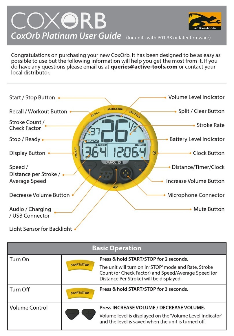
Active Tools CoxOrb Platinum user guide

