Heal Force Smart-Mini Operation manual

Smart-Mini
Water Purification System
Operation and Service Manual
Version:1501

Notice
If it is the first time for you to use our product, please carefully read this operating and
maintenance manual which will give you a lot of help. We take responsibility for regular
maintenance and repair work instead of consequences caused by improper operation.
The content of the publication is subject to change and/or updating without notice. The
content of this manual is only for reference use. The manufactory and the distributors shall
not be responsible for losses caused by incorrect description or misuse of this manual. The
graphics contained in the manual are as general representative which may have some errors
compared to entity. But the description is definitely match the function.
In accordance with copyright law, the company holds and retains the exclusive right to
all the works. Without written consent provided by company, any other organization or
individual has no right to any form of manual changes.
Preface
Thank you for using Smart-Mini water purification system designed and manufactured
by Shanghai Canrex Analytic Instrument Co, Ltd.
If you have any good suggestion, Please contact us, we will improve our products and
after sale service continuously.
Global Exclusive Agent: Healforce development (hongkong) Co. ltd. Tel: (00852)28987303
China Exclusive Agent: Nison Instrument (Shanghai) Co. ltd. Tel: (8621)62728646
Manufacture: Shanghai Canrex Analytic Instrument Co. ltd. Tel: (8621)50911997
ISO 9001:2008 Certificate

I
Contents
Chapter 1 General.....................................................................................................................1
1.1 Confirm the ordering products.......................................................................................1
1.2 Safety information......................................................................................................... 1
1.3 System operating environment...................................................................................... 1
1.4 warnings signal.............................................................................................................. 2
Chapter 2 System Introduction............................................................................................... 3
2.1 System principle.............................................................................................................3
2.2 Technical features.......................................................................................................... 3
2.3 Specifications for the system......................................................................................... 4
2.4 Diagram of the Smart-Mini system................................................................................5
Chapter 3 Instructions before installation..............................................................................7
3.1 check before installation................................................................................................ 7
3.2 Option spare parts.......................................................................................................... 7
3.2.1 Systematic data recording package CR-SP840....................................................7
3.2.2 Enhanced pretreatment cartridge CR-SP102....................................................... 7
Chapter 4 Installation...............................................................................................................9
4.1 Pipeline connections...................................................................................................... 9
4 .2 Signal cable connection.............................................................................................. 10
4.3 Pretreatment installation.............................................................................................. 10
4.3.1 open the side door of the main unit....................................................................10
4.3.2 The position of the main components................................................................ 10
4.3.3 Installation of pretreatment cartridge.................................................................11
4.3.4 Installation of ultra-purification cartridge (CR-SP302M)................................. 12
4.3.5 Installation of ultra-purification cartridge(CR-SP303M).................................. 12
Chapter 5 Parameter setting and operation......................................................................... 14
5.1 Control panel area........................................................................................................ 14
5.2 LCD display area......................................................................................................... 14
5.3 symbols and graphics for LCD display........................................................................14
5.4 Function Keypad..........................................................................................................15
5.5 Operation......................................................................................................................15
5.6 Parameters setting........................................................................................................ 17
5.6.1 Alarm Settings....................................................................................................18
5.6.2 Calendar setting................................................................................................. 21
5.6.3 Volume of taking product water setting............................................................. 22
5.6.4 Dispensing flow setting......................................................................................22
5.6.5 Ultra-pure water quality setting......................................................................... 23
5.6.6 Unit selection..................................................................................................... 23
Chapter 6 Maintenance.......................................................................................................... 25
6.1 Routine maintenance....................................................................................................25
6.2 Periodic maintenance................................................................................................... 25
6.3 Maintenance works and service works........................................................................ 26
6.3.1 Into the maintenance settings.............................................................................26
6.3.2 Pre-treatment replacement................................................................................. 28

II
6.3.3 RO membrane replacement................................................................................29
6.3.5 UV lamp replacement........................................................................................ 33
6.3.6 Micro-filter replacement.................................................................................... 34
6.3.7How to re-installation when the cartridges are not installed in the right place...36
6.4 System status check..................................................................................................... 36
6.5 Data record of system.................................................................................................. 37
6.7 Restore factory settings................................................................................................39
Chapter 7 Troubleshooting.....................................................................................................40
7.1 No display.................................................................................................................... 40
7.2 Making RO water is too low........................................................................................40
7.3 The pure water conductivity is too high....................................................................41
7.4 Ultra-pure water resistivity is too low......................................................................... 41
7.5 The flow rate of ultra-pure water is too low................................................................ 41
Chapter 8 Order information................................................................................................ 42
8.1 Consumable..................................................................................................................42
8.2 Option parts..................................................................................................................42
Chapter 9 Appendix................................................................................................................43
Appendix 1 Fuse replacement............................................................................................43
Appendix 2 pressure limiter installation............................................................................ 44
Appendix 3 inlet valve unit installation............................................................................. 45
Appendix 4 Leakage protection sensor installation........................................................ 46
Appendix 5 Components connection to main-board......................................................... 47

1
Chapter 1 General
1.1 Confirm the ordering products
The manual is written for Smart-Mini series water purification system
The content of the manual can lead users to installation, operation and maintenance of
the Smart-Mini series water purification system
We strongly recommend our users to read and understand the content of the manual
before installation, operation and maintenance
You can easily find the model of the system in the nameplate at the back of the system.
Please contact Shanghai Canrex Analytic Instrument Co., Ltd if you find out any
incorrect description in this manual.
1.2 Safety information
You must use the safety norms according to this manual before using the Smart-Mini
system, especially water and power supply. It is necessary to refer to this manual when you
install or operate the Smart-Mini system. Unqualified using environment will endanger the
normal operation, or even damage the whole system.
The installation, commissioning and maintenance of the equipment can only be
completed by Heal Force or its authorized agents. Heal Force did not responsible for duties
and responsibilities if the equipment is disassembled by unauthorized dealer or service
personnel.
1.3 System operating environment
Indoor sue
Avoid direct sunlight
Between 0-2000 meters altitude
Ambient temperature: 4-45℃
Operating Voltage: AC 220V 50 Hz OR 110V 60Hz
Inlet pressure: 0.1-0.4MPA.
The fluctuation range of the main power supply can be 10% of the normal voltage.
Transient over-voltage power supply is grade 2.
There is an drains around the equipment(1 meters)
Adequate indoor ventilation
Mounting surface must be fixed, level, and not burning
Avoid direct sunlight
2
No heat source next to the equipment.
Be away from strong magnetic field.
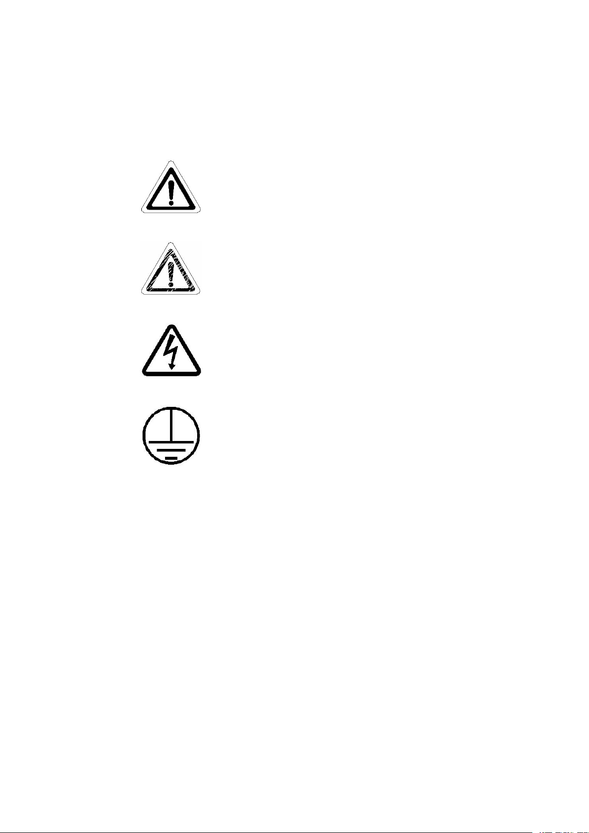
1.4 warnings signal
Note alert you to pertinent facts and conditions, please
read this operation and service manual carefully before
you operate the main system
Caution: Caution alert you to the possibility of damage to
the equipment, and water in pipe may spill out when the
cartridge is installed OR replaced.
Danger: Danger alert to a possibility of personal injury.
Power supply must be firmly grounded

3
Chapter 2 System Introduction
2.1 System principle
Smart-Mini Series is an advanced essential laboratory equipment, widely used in trace
analysis, diagnostics, toxicology, precision optics laboratories, as well as in hospital, research
institute and other water quality monitor department. The device adopted advanced modular
design, CPU auto-control technology, highly integrated water treatment equipment. It is the
new generation of intelligent water purification system with intellectual property.
The feed water of Smart-Mini system is ordinary tap water. The feed water is passing
through the multi-channel process of pretreatment cartridge, reverse osmosis cartridge,
purification cartridge, Ultra-purification cartridge ,UV sterilizer, Micro-filter cartridge. The
quality of ultrapure water can reach the resistivity of 18 MΩ.cm, and eliminating bacteria.
2.2 Technical features
Product line is abundant, as many as a hundred variety, to meet individual needs.
Disposable integrated cartridge simplifies operation. It takes less time to replace any
component
Modular design concept, including pretreatment cartridge, reverse osmosis,
purification cartridge Self-diagnostic microprocessor control system monitors major
parameters and alarm to ensuring the main system at optimize operation status.
Advanced CPU self-controlled technology can determine the configuration. The
system will shutdown automatically when the feed water is shortage and auto flush when the
main system re-stared. Double channel design for pure water and ultrapure water.
Special UV sterilizer control technology make the UV light work only when
ultrapure water is produced, thus can extend life time of UV lamp.
Interactive LCD display affords user optimum convenience, with indication on
conductivity, resistivity, temperature, operate mode, volume dispense products water.
3-channel resistivity sensors, equipped with temperature compensation function,
comprehensively monitor system operation and water quality variation.
Two hours standby mode with various types of loop disinfection. Using hydrogen
peroxide as disinfectant to protect operator and filtration cartridge, and guarantee the quality
of ultrapure water.
Leakage protection unit(optional). The main unit cut off the inlet water and send an
alarm signal if water leakage occurs.
A special connection process is applied for the Smart-Mini system, eliminating the

4
risk of RO membranes seepage when the main unit is in standby mode.
Volume dispense function (0.1-25L adjustable) or water producing amount according
to your needs
PIN-coded access to software set points prevent unauthorized changes to operation or
system settings.
RS232 port allows for data collection and permanent record of water quality and
system parameters--essential for compliance with good laboratory practice guidelines.
With remote monitor software (option),you can remote the water system on the
computer.
2.3 Specifications for the system
Smart-Mini
Feed water
requirement
Conductivity μS/cm@25℃
<400
Pressure MPa
0.1~0.4
Temperature ℃
5~40
Pure water
Specification
Ion rejection rate %@25℃
≥95
Bacteria remove %
>99
Products resistivity MΩ.cm
>18
Make rate* L/H@25℃
25-30
Dispensing rate L/H
25-30
TOC** ppb
1-10
Particles***(0.22μm) /ml
<1
Bacteria*** cfu/ml
1
Power Consumption W
85
Weight kg
30
Main System
Dime. W*D*H
525*314*571
Note:
* The making rate will be changed with temperature variation. (3% per 1℃)
** The feed water TOC is less than 1000ppb.
*** with 0.22um final filter cartridge

5
2.4 Diagram of the Smart-Mini system
Smart-Mini
6
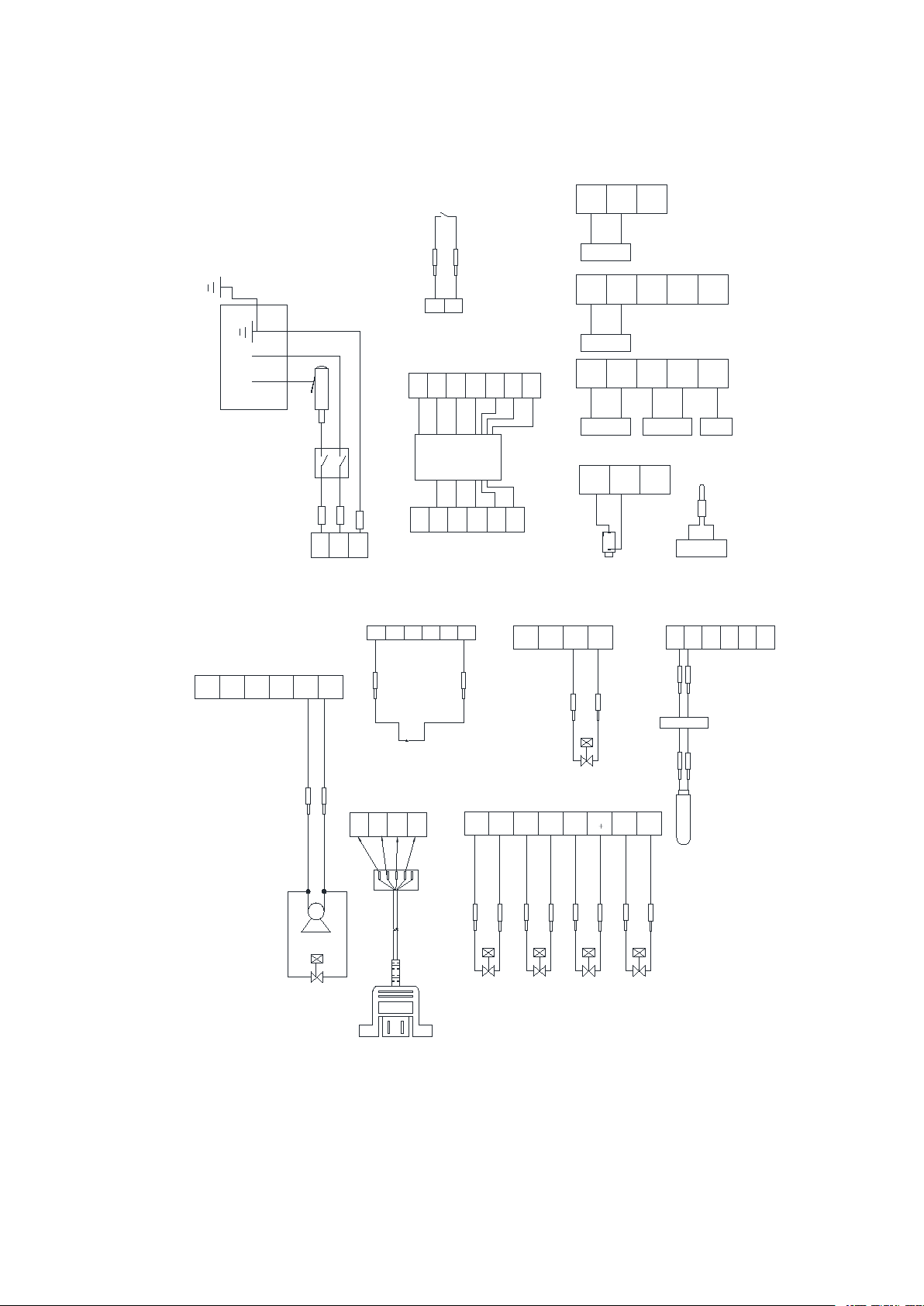
Diagram of controller and measurement
N
L
220V(IN)
+
K1 switch
fuse
plug GNDCELL CELL RT RT
B
IGND
CIGND
P1+
P2
cell 1
GNDCELL
D +IGNDE +IGND
P1
P8
P7
green yell
EE
N
L
N
L
E
L
temp
cell 2
solenoid D
GNDCELL CELL RT RT
P3
cell 3
EGND
Vio blue
vio blue
gnd
red
yel bla
blu gre
IGND P2+ IGND
LNE
red bla
P11
R80 trasformer
ACC
6
P13
P12
GND ACD ACA ACB ACE ACF
yel blu yel whi whi bro bro
5 4 3 2 1
yel whi y g bla red
CELL
P5
low pressure sensor
BREAK IN
black
red
r y
y g w b
(220V)
(110V)
CELL CELL GND
P4
water sensor
red bla
J socket
J plug
pump 1
solenoid valve H
redbla
black
green
V+
P9 D- D+
+
+J
IGNDKIGND
solenoid valve J
red
bla
solenoid E
red bla
solenoid B
red bla
solenoid C
red bla
P15
P6
high pressure switch
+5
bla
red
1 2 3 4 5
red
yel
wui
bla
P14
220V EGND
trasformer
UV lamp
IGND A+
V-
220V EGND
UV2 UV1
red whi grebla
USB socket

7
Chapter 3 Instructions before installation
3.1 check before installation
Users please ensure whether the product you received is your purchase before
installation.
You had batter check all items according the packing list.
Whether the power site is close to the system.
Whether the feed water meets the requirements.
Whether the feed water pressure is normal.
Whether the feed water supply is nonstop.
Whether the feed water pipe has1/2″NPTF whorl connector.
Whether it is needed another frame for wall installation.
Whether the strength of the wall can bear the system (including tank full of water)
weight.
Whether the system’s height can clearly observe both LCD screen and keypad
operations on control panel.
Whether there is adequate space to substitute supplies and connecting pipe as well
around and behind the system.
Whether you have installed more than 1/2 ″drains, not more than one meter far
away from the system, intended for discharging waste-water and water overflowing.
Whether the installment circumstances are consistent with the regulations.
Whether there is reserved space if you are going to install RS232 signal accessing
your computer.
Whether there is reserved space if you are looking forward to having moving handle
and pedal switch installed.
3.2 Option spare parts
3.2.1 Systematic data recording package CR-SP840
It includes systematic data recording software and RS232 connecting signal. Using it,
you can easily have SMART-MINI system and your computer connected, on which you can
install and record you using this recording system and water quality.
3.2.2 Enhanced pretreatment cartridge CR-SP102

8
Enhanced pretreatment cartridge is a multi-stage pretreatment module to removes the
impurities in tap water including suspended particulates, colloids, microorganisms, organics,
chlorine and heavy metals to ensure the following purification modules work properly.
9
Chapter 4 Installation
It is important for the user to master installation and removal of quick connector. If user
dose not operate properly will lead to water leakage, quick connector damage and pipeline
broken,
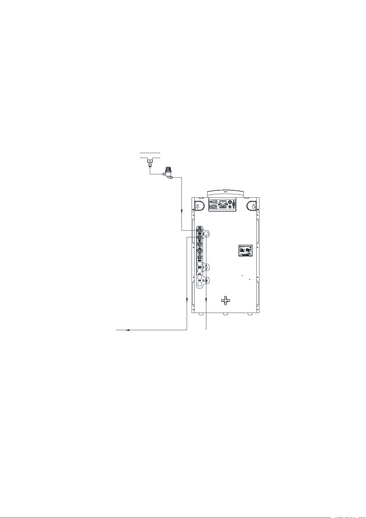
4.1 Pipeline connections
pre-filter
drain
feed water
drain drain
A Get two black tubes (1 / 4 ", 2m), one ends of the tube connect to the "DRAIN1" and
"DRAIN2" at the back of main unit, the other ends into the external drainage pipes which
have been pre-installed.
B Get a blue tube (1 / 4 ", 20cm) and Pre- filter, one end of the blue tube connects to
the tap water connector, the other end connects to the Pre-filter “in”.
Get a blue tube (1 / 4 ", 2m), one end connect to the Pre- filter “outlet”, the other end
connect into the “feed” at the back of main unit.
10
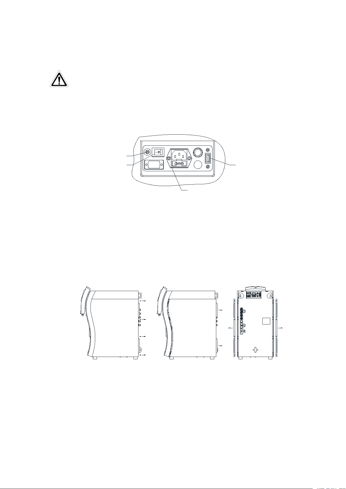
4 .2 Signal cable connection
1, socket for leakage sensor 2, Power on/off 3, socket for power supply 4,socket
for USB(option) .
4.3 Pretreatment installation
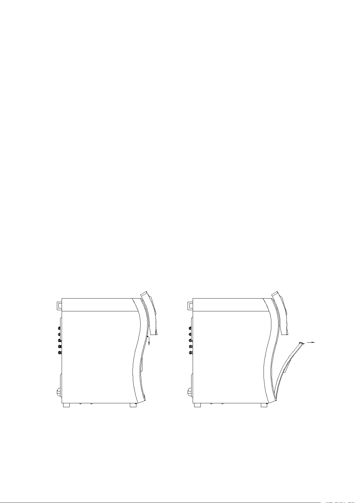
4.3.1 open the side door of the main unit
Opening method is showed below
A B C
Step A: unscrew the screw of the side door with a screwdriver.
Step B: pull the handle of the side door with both hands, forced back to pull the a side
door out of 10mm ~ 13mm.
Step C: carry out the side door.
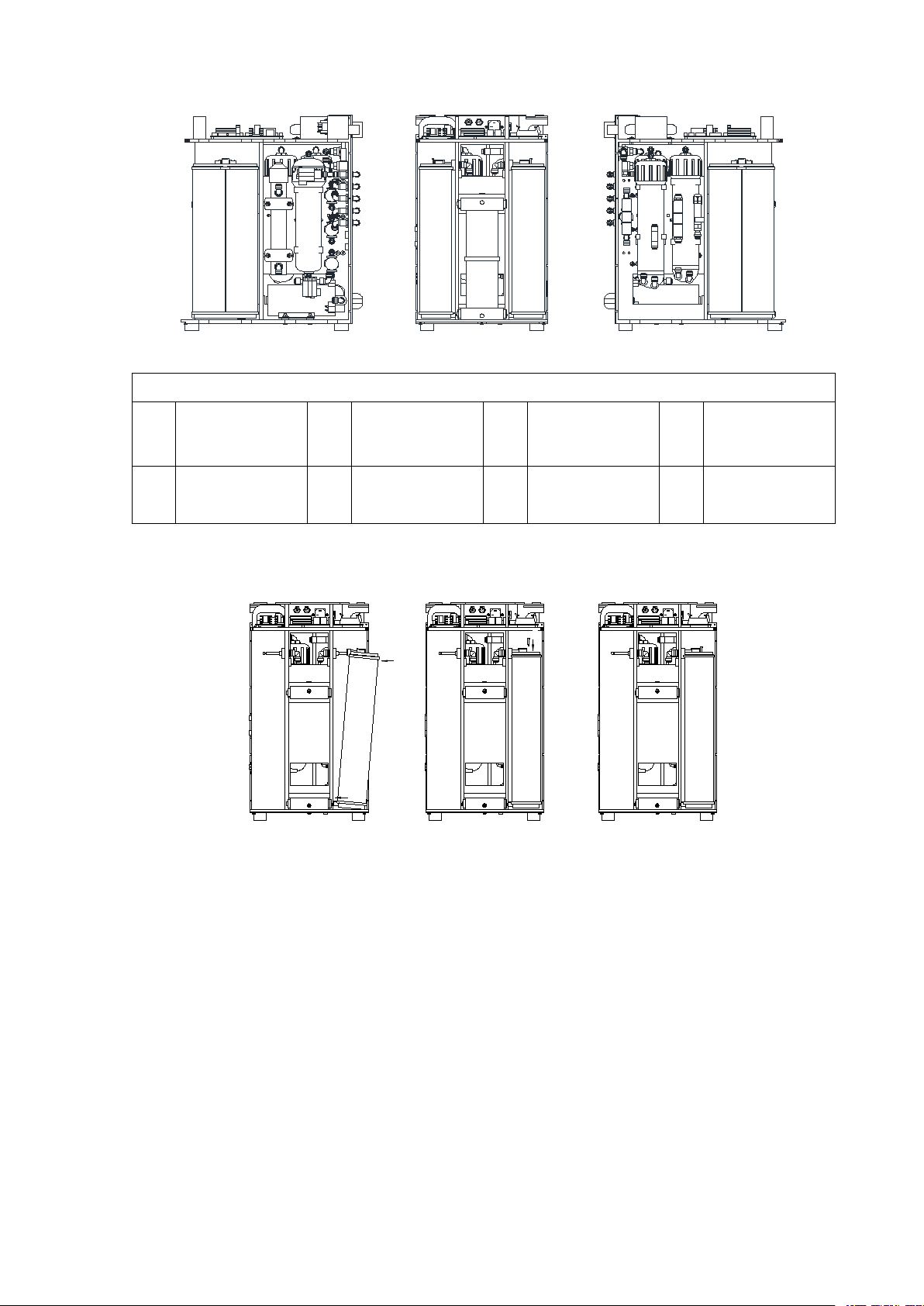
4.3.2 The position of the main components
1
2
3
4
11
A
B
CD E
F
A D
Instructions to the main component
A
Pretreatment
cartridge
B
RO cartridge
C
UV light
D
Ultra-Purifica
tion cartridge
E
Ultra-Purificatio
n cartridge
F
Micro-filter
4.3.3 Installation of pretreatment cartridge
A
B
C
D
Confirm the Smart-Mini system is power off.
Pretreatment cartridge is installed in the right chamber of smart-Mini system.
Get the pretreatment cartridge from the box (make sure number is correct for the
CR-SP101M), open the vacuum bag, remove protection cover for the inlet and outlet of
pretreatment cartridge. Make sure there is a black “O” ring in the inlet and outlet, which is in
the bottom of the hole.
Use pure water to make the black "O" rings wet. Do not use lubricants for lubrication,
such as glycerol or Vaseline or other lubricant.
12
Place the square tenon at the low of the pretreatment into the corresponding square hole
on the main unit, shown as in the figure “A” above.
Push the joint at the up of the pretreatment cartridge to the main unit shown as in the
figure “B” above. Make sure the "O"-rings of pretreatment cartridge can be completely sealed
with the joints.
There is locking plate connected with nylon line on the joints of main unit. Insert the
locking plate into the slot of metal bar, as shown in the figure C above.
Pretreatment cartridge installation is complete. As shown in Figure D.
4.3.4 Installation of ultra-purification cartridge (CR-SP302M)
Remove the left side door (front view), please refer to of this chapter.
Ultra-Purification cartridge is installed in the left chamber of Smart-Mini system.
Get the ultra-purification cartridge from the box (make sure number is correct for the
CR-SP302M).
The operation method: please refer to section4.3.3 of this chapter.
4.3.5 Installation of ultra-purification cartridge(CR-SP303M)
Open the front door of the main unit
AB
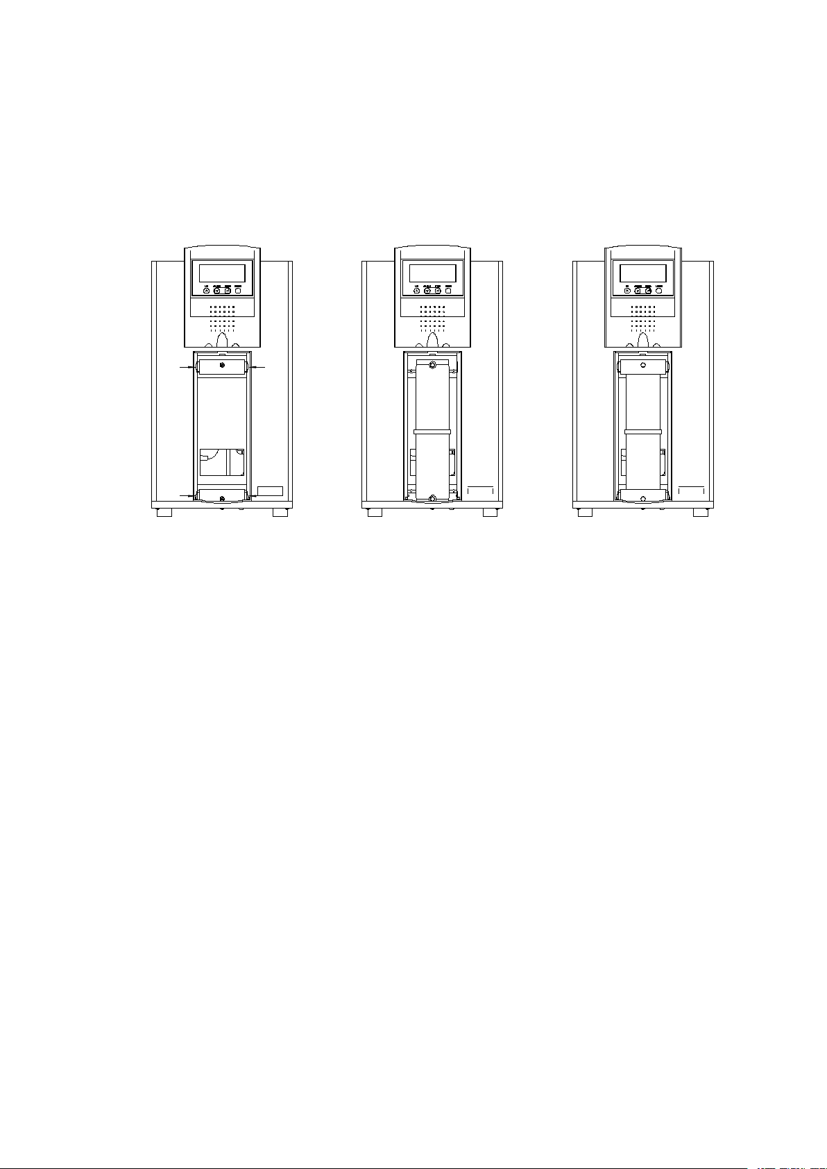
13
Press and pull the latch at the top of the front door, to remove the front door (press down
about 3mm , do not press down hardly which may cause deformation or even fracture
bayonet). As shown in figure “A””B”
Installation of purification cartridge(CR-SP301MS)
A B C
Open the front door of the Smart-Mini system. Please refer to this chapter.
Open the front door , the cabinet of ultra-purification cartridges has upper and lower
latch, As shown in Figure A
Take out the ultra-purification cartridge from the box (make sure number is correct for
the CR-SP303M), open the vacuum bag, remove protection cover for the port of cartridge.
Make sure there is a black “O” ring in the ports, which is in the right position.( should be
close to the inlet and outlet inside the convex shoulder). If the position is not right, Please
adjust it to the right position.
Wet the "O"-rings with ultra-pure water. Do not use lubricants for lubrication, such as
glycerol or Vaseline or other lubricant.
Push the ultra-purification cartridge firmly into place , Both the top and bottom ports of
the cartridge have to be fully seated shown as figure ”B” above.
Place the latch as origin. Make sure that both the top latch and bottom latch are fully
closed. Each latch should “click” when it is fully closed.
Install the front door as this chapter. The purification cartridge installation is completed
14
Chapter 5 Parameter setting and operation
5.1 Control panel area
A
B
A: dashed box for the LCD display area.
B: dashed box for the function keypad board.
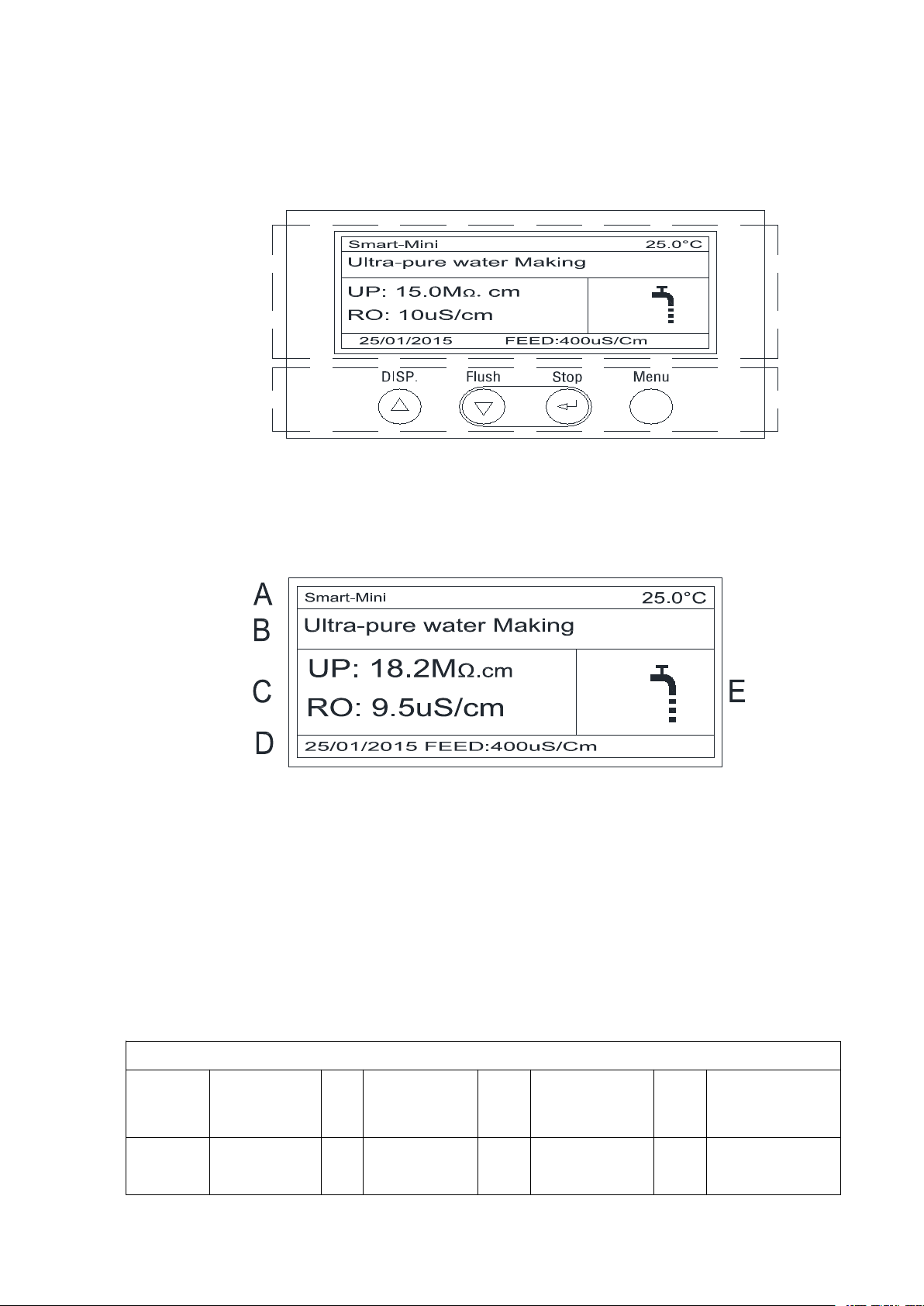
5.2 LCD display area
A: system model and the current temperature display .
B: current status
C: product water quality and Volume dispense status.
D: date and feed water conductivity.
E: graphic for display status.
5.3 symbols and graphics for LCD display
symbols
FEED
Feed water
conductivity
RO
Pure water
conductivity
UV
UV light
DS
RO deionization
rate
PF
Pretreatment
cartridge
MF
Micro-filter
Vol.
Disp.
Fixed Volume
Dispensing
UP
Products
resistivity

15
graphics
Without feed
water
System leakage
Feed water
low quality
Pretreatment
failure
RO failure
MF
Micro-filter
failure
UV light failure
Water tank level
RO failure
Ultrapure water
producing
Ultrapure water
recycle
Purification
cartridge failure
5.4 Function Keypad
There are 4 function keypads in Smart-Mini system: disp./ ▲, Flush/ ▼, Stop/ and
Menu
Disp./ ▲Dispense product water keypad at the operation, it will be become
adjusting keypad at the menu mode.
Flush/ ▼RO cartridge flush keypad at the operation, it will be become adjusting
keypad at the menu mode.
Stop/
Stopping water dispensing or flushing at the operation, it will be become
confirmation keypad at the menu mode. press the button to stop the water
producing or flushing process. After entering the settings menu it becomes the
confirmation keypad.
Menu Parameter setting keypad.
5.5 Operation
Turn on feed water supply. Ensure that all the pipe connecting parts have no leaking.
Switch on the power supply at the back of the main unit.
After the main unit is powered on, LCD will display a welcome message, which is
followed by the current state of the system. The system will remain in flushing status about 3
minute. As shown below:
Table of contents
Other Heal Force Water Filtration System manuals

Popular Water Filtration System manuals by other brands


Sartorius
Sartorius Sartolab RF 150 Sartolab BT 150 quick start guide

Oase
Oase Filtral 2500 UVC operating instructions

Clean Water Systems
Clean Water Systems Fleck 2510-XST Installation & start?up guide

Premier
Premier WP-5 Nstallation, operation and maintenance manual

Lenze
Lenze E84AZESM Series Mounting instructions

Canature
Canature RO 75 GPD 4 STAGE BP Installation and operation manual


