Heal Force Smart-NE Series Operation manual

Smart-NE Series
Water Purification System
Operation and Service Manual
Version:2004

Notice
If it is the first time for you to use our product, please carefully read this operating and maintenance
manual which will give you a lot of help. We take responsibility for regular maintenance and repair work
instead of consequences caused by improper operation.
The content of the publication is subject to change and/or updating without notice. The content of
this manual is only for reference use. The manufactory and the distributors shall not be responsible for
losses caused by incorrect description or misuse of this manual. The graphics contained in the manual
are as general representative which may have some errors compared to entity. But the description is
definitely match the function.
In accordance with copyright law, the company holds and retains the exclusive right to all the works.
Without written consent provided by company, any other organization or individual has no right to any
form of manual changes.
Preface
Thank you for using Smart-NE water purification system.
If you have any good suggestion, Please contact us, we will improve our products and after sale
service continuously.
Global Exclusive Agent: Healforce development (hongkong) Co. ltd. Tel: (00852)28987303
China Exclusive Agent: Nison Instrument (Shanghai) Co. ltd. Tel: (8621)62728646
Manufacture: Shanghai Canrex Analytic Instrument Co. ltd. Tel: (8621)50911997

ISO 9001 Certificate

I
Contents
Chapter 1 General............................................................................................................................1
1.1 Confirm the ordering products........................................................................................... 1
1.2 Safety information................................................................................................................ 1
1.3 System operating environment.......................................................................................... 1
1.4 warnings signal.....................................................................................................................1
Chapter 2 System Introduction....................................................................................................2
2.1 System principle................................................................................................................... 2
2.2 Technical features................................................................................................................ 2
2.3 Specifications for the system............................................................................................. 2
2.4 Diagram of the Smart-NE system......................................................................................3
Chapter 3 Instructions before installation................................................................................ 4
3.1 Check before installation.....................................................................................................4
3.2 Option spare parts............................................................................................................... 4
3.2.1 Pressure reducing valve CR-SP829.......................................................................4
3.2.2 Systematic data recording package CR-SP840................................................... 4
3.2.3 Enhanced pretreatment cartridge CR-SP102....................................................... 4
3.2.4 Water leakage sensor CR-SP846........................................................................... 4
Chapter 4 Installation..................................................................................................................... 5
4.1 Accessory installation of storage tank.............................................................................. 5
4.2 Pipeline connections............................................................................................................5
4.2.1 Feed pipeline and drain pipeline installations....................................................... 5
4.2.2 Pipeline connections between main unit and water tank.................................... 5
4.2.3 Pipeline connections between main unit and RWD............................................. 6
4.3 Signal cable connection...................................................................................................... 6
4.3.1 Level cable..................................................................................................................7
4.3.2 Pump power cable.....................................................................................................7
4.3.3 Cable connect between main unit and RWD........................................................ 7
4.4 Cartridge installation............................................................................................................7
4.4.1 Open the side door of the main unit....................................................................... 7
4.4.2 The position of the main components.................................................................... 7
4.4.3 Installation of pretreatment cartridge...................................................................... 8
4.4.4 Installation of purification cartridge(CR-SP303M)................................................ 8
Chapter 5 Parameter setting and operation........................................................................... 10
5.1 Control panel area............................................................................................................. 10
5.2 LCD display area................................................................................................................10
5.3 Symbols and graphics for LCD display...........................................................................10
5.4 Function Keypad................................................................................................................ 10
5.5 Operation.............................................................................................................................11
5.6 Parameters setting.............................................................................................................12
5.6.1 Alarm Settings.......................................................................................................... 12
5.6.2 Calendar setting.......................................................................................................14
5.6.3 Volume of taking product water setting................................................................ 14
5.6.4 Dispensing flow setting........................................................................................... 14
5.6.5 Ultra-pure water quality setting..............................................................................15
5.6.6 Unit selection............................................................................................................15
Chapter 6 Maintenance................................................................................................................ 16
6.1 Routine maintenance.........................................................................................................16
6.2 Periodic maintenance........................................................................................................16
6.3 Maintenance works and service works...........................................................................16
6.3.1 Pre-filter cleaning.....................................................................................................16
6.3.2 Into the maintenance settings................................................................................17

II
6.3.3 Pre-treatment replacement.................................................................................... 17
6.3.4 RO membrane replacement...................................................................................18
6.3.5 Purification cartridge replacement........................................................................ 20
6.3.7 Micro/Ultra-filter replacement.................................................................................21
6.3.8 Re-install the cartridges..........................................................................................22
6.4 System status check..........................................................................................................22
6.5 Obligate level setting......................................................................................................... 23
6.6 Data record of system....................................................................................................... 23
6.7 Restore factory settings.................................................................................................... 24
6.8 Main unit disinfection.........................................................................................................25
Chapter 7 Troubleshooting......................................................................................................... 27
7.1 No display............................................................................................................................27
7.2 Making RO water is too low..............................................................................................27
7.3 The pure water conductivity of Smart-NE is too high................................................... 27
7.4 Ultra-pure water resistivity is too low.............................................................................. 27
7.5 The flow rate of ultra-pure water is too low....................................................................27
Chapter 8 Order information...................................................................................................... 28
8.1 Consumable........................................................................................................................28
8.2 Option parts.........................................................................................................................28
Chapter 9 Appendix...................................................................................................................... 29
Appendix 1 Fuse replacement................................................................................................29
Appendix 2 Pressure reductor installation............................................................................ 29
Appendix 3 Inlet valve unit installation.................................................................................. 30
Appendix 4 Electrical connections......................................................................................... 30

1
Chapter 1 General
1.1 Confirm the ordering products
The manual is written for Smart-NE series water purification system
The content of the manual can lead users to installation, operation and maintenance of the
Smart-NE series water purification system
We strongly recommend our users to read and understand the content of the manual before
installation, operation and maintenance
You can easily find the model of the system in the nameplate at the back of the system.
1.2 Safety information
You must use the safety norms according to this manual before using the Smart-NE system,
especially water and power supply. It is necessary to refer to this manual when you install or operate the
Smart-NE system. Unqualified using environment will endanger the normal operation, or even damage
the whole system.
The installation, commissioning and maintenance of the equipment can only be completed by its
authorized agents. We did not responsible for duties and responsibilities if the equipment is
disassembled by unauthorized dealer or service personnel.
1.3 System operating environment
Indoor use
Avoid direct sunlight
Between 0-2000 meters altitude
Ambient temperature: 4-45℃
Operating Voltage: 220-230V AC 50/60Hz
Inlet pressure: 0.1-0.4MPA.
The fluctuation range of the main power supply can be 10% of the normal voltage.
Transient over-voltage power supply is grade 2.
There is an drains around the equipment(1 meters)
Adequate indoor ventilation
Mounting surface must be fixed, level, and not burning
Avoid direct sunlight
No heat source next to the equipment.
Be away from strong magnetic field.
1.4 warnings signal
Note alert you to pertinent facts and conditions, please read this operation and
service manual carefully before you operate the main system
Caution: Caution alert you to the possibility of damage to the equipment, and
water in pipe may spill out when the cartridge is installed OR replaced.
Danger: Danger alert to a possibility of personal injury.
Power supply must be firmly grounded

2
Chapter 2 System Introduction
2.1 System principle
Smart-NE Series is an advanced essential laboratory equipment, widely used in trace analysis,
diagnostics, toxicology, precision optics laboratories, as well as in hospital, research institute and other
water quality monitor department. The device adopted advanced modular design, CPU auto-control
technology, highly integrated water treatment equipment. It is the new generation of intelligent water
purification system with intellectual property.
The feed water of Smart-NE system is ordinary tap water. The feed water is passing through the
multi-channel process of pretreatment cartridge, reverse osmosis cartridge, EDI, Ultra-purification
cartridge, UV sterilizer, Ultra-filter cartridge. The quality of ultrapure water can reach the resistivity of 18
MΩ.cm and eliminating bacteria.
2.2 Technical features
Product line is abundant, as many as a hundred variety, to meet individual needs.
Disposable integrated cartridge simplifies operation. It takes less time to replace any component
Modular design concept, including pretreatment cartridge, reverse osmosis, purification cartridge
Self-diagnostic microprocessor control system monitors major parameters and alarm to ensuring the
main system at optimize operation status.
Advanced CPU self-controlled technology can determine the configuration. The system will
shutdown automatically when the feed water is shortage and auto flush when the main system re-stared.
Double channel design for pure water and ultrapure water.
Special UV sterilizer control technology make the UV light work only when ultrapure water is
produced, thus can extend life time of UV lamp.
Interactive LCD display affords user optimum convenience, with indication on conductivity, resistivity,
temperature, operate mode, water tank level, volume dispense products water.
4-channel resistivity sensors, equipped with temperature compensation function, comprehensively
monitor system operation and water quality variation.
Two hours standby mode with various types of loop disinfection. Using hydrogen peroxide as
disinfectant to protect operator and filtration cartridge, and guarantee the quality of ultrapure water.
A special connection process is applied for the Smart-NE system, eliminating the risk of RO
membranes seepage when the main unit is in standby mode, ensuring the qualified water into the water
tank.
30Lor 60L storage tank with 5 level sensor, with optional air filter and UV sterilizer for water tank,
which provides flexible solutions for different water usage.
Adjustable level of water system start to making EDI water, keep the EDI water in the storage tank
fresh according to the user demand.
Volume dispense function (0.1-25L adjustable) or water producing amount according to your needs
PIN-coded access to software set points prevent unauthorized changes to operation or system
settings.
Remote water producing function (optional)
USB port allows for data collection and permanent record of water quality and system
parameters--essential for compliance with good laboratory practice guidelines.
With remote monitor software (option), you can remote the water system on the computer.
2.3 Specifications for the system
Feed water requirement
Conductivity μS/cm@25℃
<400
Note:
* The making
rate will be changed
with temperature
variation. (3% per
1℃)
** The feed
water TOC is less
than 1000ppb.
*** with 0.22um
final filter cartridge
**** with
Ultra-filter cartridge
Pressure MPa
0.1~0.4
Temperature ℃
5~40
Pure water
Ion rejection rate %@25℃
≥95
Bacteria remove %
>99
Make rate* L/H@25℃
25-30
High-pure water
resistivity MΩ.cm
>10
Make rate L/H
10-15
Ultra-Pure water
resistivity MΩ.cm
>18
TOC** ppb
1-10
Endotoxin*** Eu/ml
<0.001Eu/ml
3
Particles****(0.22μm)/ml
<1
Dispensing rate L/H
60-100
Power Consumption W
150
Weight kg
38
Storage tank
30L
Main System Dime. W*D*H
525*314*571
Storage Tank Dime.W*D*H
430*380*580
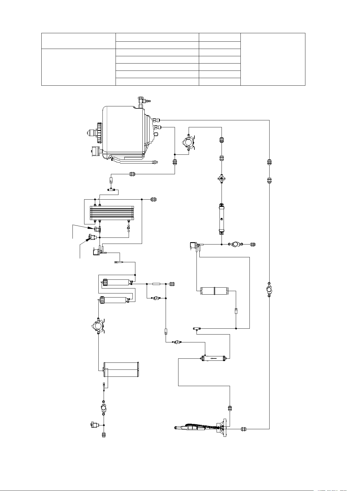
2.4 Diagram of the Smart-NE system
FEEDFEED
lowlow pressurepressure switch1switch1
solenoidsolenoid valveHvalveH
conductivityconductivity cell1cell1
pretreatmentpretreatment carteidgecarteidge
pump1pump1
reversereverse osmosisosmosiscartridgecartridge
flowflow controlcontrolvalve2valve2
solenoidsolenoid valveCvalveC
DRAIN1DRAIN1
conductivityconductivity cell4cell4
solenoidsolenoid valveBvalveB
OUTOUT
ININ
OUTOUT
ININ
pressurepressure reducingreducing valvevalve
solenoidsolenoid valveAvalveA
highhigh purepure waterwater
ultra-purificationultra-purification cartridgecartridge
resistivityresistivity cell3cell3
UFUF cartridgecartridge
solenoidsolenoid valveEvalveE
RWD1-1RWD1-1
RECREC RECREC
solenoidsolenoid valveDvalveD
checkcheck valve3valve3
solenoidsolenoid valveJvalveJ
checkcheck valve2valve2
DRAIN2DRAIN2
highhigh pressurepressure switchswitch
flowflow controlcontrolvalve1valve1
resistivityresistivity cell2cell2
pump2pump2
lowlow pressurepressure switch2switch2
RWD1-2RWD1-2
UVUV lamplamp
checkcheck valve1valve1
EDIEDI
waterwatertanktank
RWDRWD

4
Chapter 3 Instructions before installation
3.1 Check before installation
Users please ensure whether the product you received is your purchase before installation.
You had batter check all items according the packing list.
Whether the power site is close to the system.
Whether the feed water meets the requirements.
Whether the feed water pressure is normal.
Whether the feed water supply is nonstop.
Whether the feed water pipe has1/2″NPTF whorl connector.
Whether it is needed another frame for wall installation.
Whether the strength of the wall can bear the system (including tank full of water) weight.
Whether the system’s height can clearly observe both LCD screen and keypad operations on control
panel.
Whether there is adequate space to substitute supplies and connecting pipe as well around and
behind the system.
Whether you have installed more than 1/2″ drains, not more than one meter far away from the
system, intended for discharging waste-water and water overflowing.
Whether the installment circumstances are consistent with the regulations.
Whether there is reserved space if you are going to install USB signal accessing your computer.
Whether there is reserved space if you are looking forward to having moving handle and pedal
switch installed.
3.2 Option spare parts
3.2.1 Pressure reducing valve CR-SP829
Please purchase this product additionally when the feed water pressure is too high(>0.4MPa).
This component can reduce pressure to 0.4Mpa below.
3.2.2 Systematic data recording package CR-SP840
It includes systematic data recording software and USB connecting signal. Using it, you can easily
have Smart-NE system and your computer connected, on which you can install and record you using
this recording system and water quality.
3.2.3 Enhanced pretreatment cartridge CR-SP102
Enhanced pretreatment cartridge is a multi-stage pretreatment module to removes the impurities in
tap water including suspended particulates, colloids, microorganisms, organics, chlorine and heavy
metals to ensure the following purification modules work properly.
3.2.4 Water leakage sensor CR-SP846
It will cut off systematic water supply in time when it breaks down or water leaks out, preventing
further leakage.
5
Chapter 4 Installation
It is important for the user to master installation and removal of quick connector. If user dose not
operate properly will lead to water leakage, quick connector damage and pipeline broken.
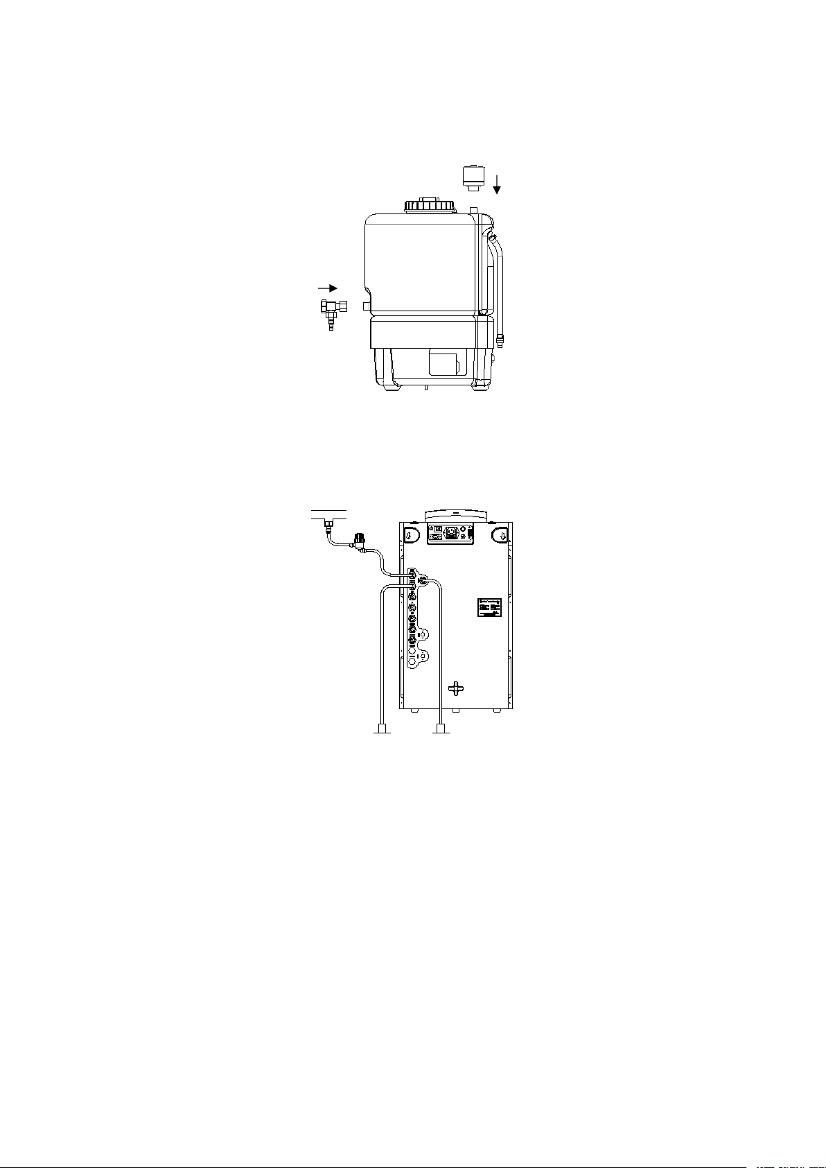
4.1 Accessory installation of storage tank
First to twine the 1/2’ NPTF outlet in the front of the storage tank with Teflon tape ,then get the RO
dispense valve connect to the outlet of storage, be sure the “O” ring and screw tight.
Get the air-filter and screw to the 1/2”NPTF outlet on the top of the storage tank according to the
clockwise sense, be sure not to screw tight.
4.2 Pipeline connections
4.2.1 Feed pipeline and drain pipeline installations
Before connecting the inlet pipe, make sure that the external water supply has been shut down to
prevent water supply pipe splashing around, resulting in unnecessary losses.
Get the quick connector and the tread sealing tape out. Wind the tread sealing tape around the 1 / 2
"NPTF connector (usually 3 to 4 laps) of pre-installed external water pipeline. And then screw on the
connector.
Cut a blue tube and prefilter, one end of the blue tube connects to the tap water connector, the other
end connects to the prefilter “in”.
Cut a blue tube, one end connects to the prefilter “outlet”, the other end connects into the “feed” at
the back of main unit.
Cut two black tubes, one ends of the tubes connect to the "DRAIN1"and “DRAIN2” at the back of
main unit, insert the other ends into the floor drain.
4.2.2 Pipeline connections between main unit and water tank
Water supply pipe
Prefilter
Floor drain

6
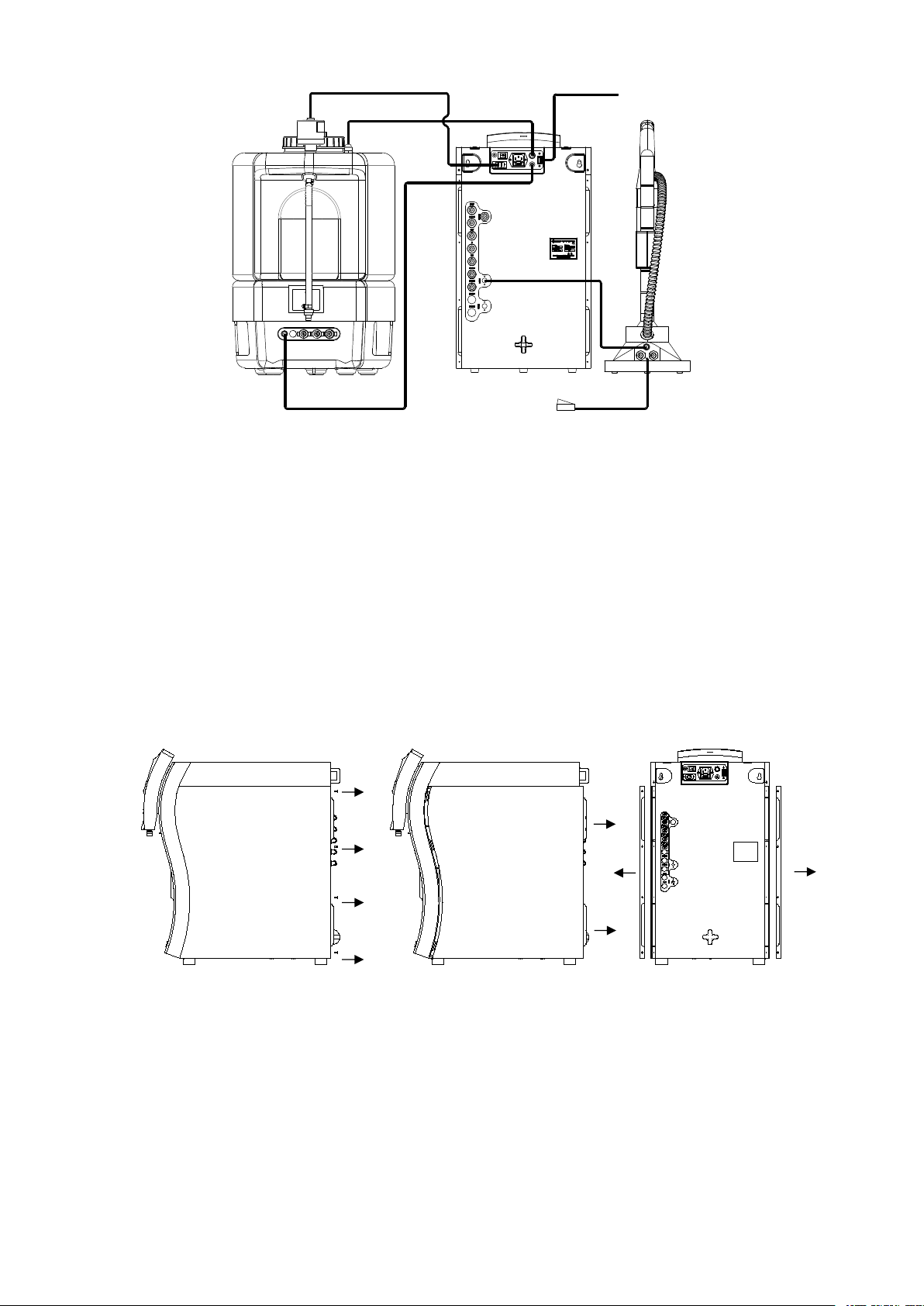
Cut a white tube, insert one end of the tube into the "OUT" on the back of main unit, and the other
end into the "IN" on the back of storage tank.
Cut a white tube, insert one end of the tube into the "IN" on the back of main unit, and the other end
into the "OUT" on the back of storage tank.
Cut a white tube, insert one end of the tube into the "REC" on the back of main unit, and the other
end into the "REC" on the back of storage tank.
Get a transparent tube (DN12mm,2m), one end of the tube connect to the air check valve at the
back of storage tank with clamp fitting, the other end into the external drainage pipes which have been
pre-installed.
4.2.3 Pipeline connections between main unit and RWD
Get a white tube, insert one end of the tube into the "RWD1-1" on the back of main unit, and the
other end into the one of the connectors on the back of RWD.
Get a white tube, insert one end of the tube into the "RWD1-2" on the back of main unit, and the
other end into the one of the connectors on the back of RWD.
4.3 Signal cable connection
1 power switch
2 power supply socket
3 level sensor socket
4 USB socket
5 tank pump socket
6 tank UV socket
Floor drain
1
2
3
5
6
4
7
4.3.1 Level cable
Connect the seven core signal cable on the top of the water storage tank to the level sensor socket
on the back of the main unit.
4.3.2 Pump power cable
Get the three core signal cable, one end connect to three core socket at the back of main unit, the
other end connect to the three core socket at the back of storage tank base.
4.3.3 Cable connect between main unit and RWD
Get the PS/2 signal cable, one end connects to the “RWD1” at the back of the main unit, the other
end connects to the PS/2 socket at the back of the remote water dispenser.
4.3.4 Main power supply cable
Make sure that the system switch status is "OFF" the switch should be in the "O"
Put the power cord plug into the power supply socket.
Insert the other end of the power cord into the external power supply outlet.
4.4 Cartridge installation
4.4.1 Open the side door of the main unit
Unscrew the screw of the side door with a screwdriver.
Pull the handle of the side door with both hands, forced back to pull the a side door out of 10mm ~
13mm.
Carry out the side door.
4.4.2 The position of the main components
Water tank
Foot control
Remote water dispenser
Main unit

8
A Pretreatment cartridge
B RO cartridge
C UV light
D EDI
E Ultrapure cartridge
F MF/UF cartridge
4.4.3 Installation of pretreatment cartridge
Confirm the system is power off.
Pretreatment cartridge is installed in the right chamber of Smart-NE system.
Get the pretreatment cartridge from the box (make sure number is correct for the CR-SP101M),
open the vacuum bag, remove protection cover for the inlet and outlet of pretreatment cartridge. Make
sure there is a black “O” ring in the inlet and outlet, which is in the bottom of the hole.
Use pure water to make the black "O" rings wet. Do not use lubricants for lubrication, such as
glycerol or Vaseline or other lubricant.
Place the square tenon at the low of the pretreatment into the corresponding square hole on the
main unit.
Push the joint at the up of the pretreatment cartridge to the main unit. Make sure the "O"-rings of
pretreatment cartridge can be completely sealed with the joints.
There is locking plate connected with nylon line on the joints of main unit. Insert the locking plate
into the slot of metal bar.
Pretreatment cartridge installation is complete.
4.4.4 Installation of purification cartridge(CR-SP303M)
Open the front door of the main unit
A
C
F
D
E
A
B
D

9
Press and pull the latch at the top of the front door, to remove the front door (press down about 3mm,
do not press down hardly which may cause deformation or even fracture bayonet).
Open the front door of the system. Please refer to this chapter.
Open the front door, the cabinet of ultra-purification cartridges has upper and lower latch.
Take out the purification cartridge from the box (make sure number is correct for the CR-SP303M),
open the vacuum bag, remove protection cover for the port of cartridge. Make sure there is a black “O”
ring in the ports, which is in the right position.( should be close to the inlet and outlet inside the convex
shoulder). If the position is not right, Please adjust it to the right position.
Wet the "O"-rings with ultra-pure water. Do not use lubricants for lubrication, such as glycerol or
Vaseline or other lubricant.
Push the purification cartridge firmly into place, Both the top and bottom ports of the cartridge have
to be fully seated.
Place the latch as origin. Make sure that both the top latch and bottom latch are fully closed. Each
latch should “click” when it is fully closed.
Install the front door as this chapter. The purification cartridge installation is completed
10
Chapter 5 Parameter setting and operation
5.1 Control panel area
DISP.DISP. FlushFlush StopStop M enuM enu
Smart-NE
Ultra-water Dispensing
25.0°C
08:00 20/09/2016
UP: 18.2 MΩ·cm
Vol Disp: OFF
A: dashed box for the LCD display area.
B: dashed box for the function keypad board.
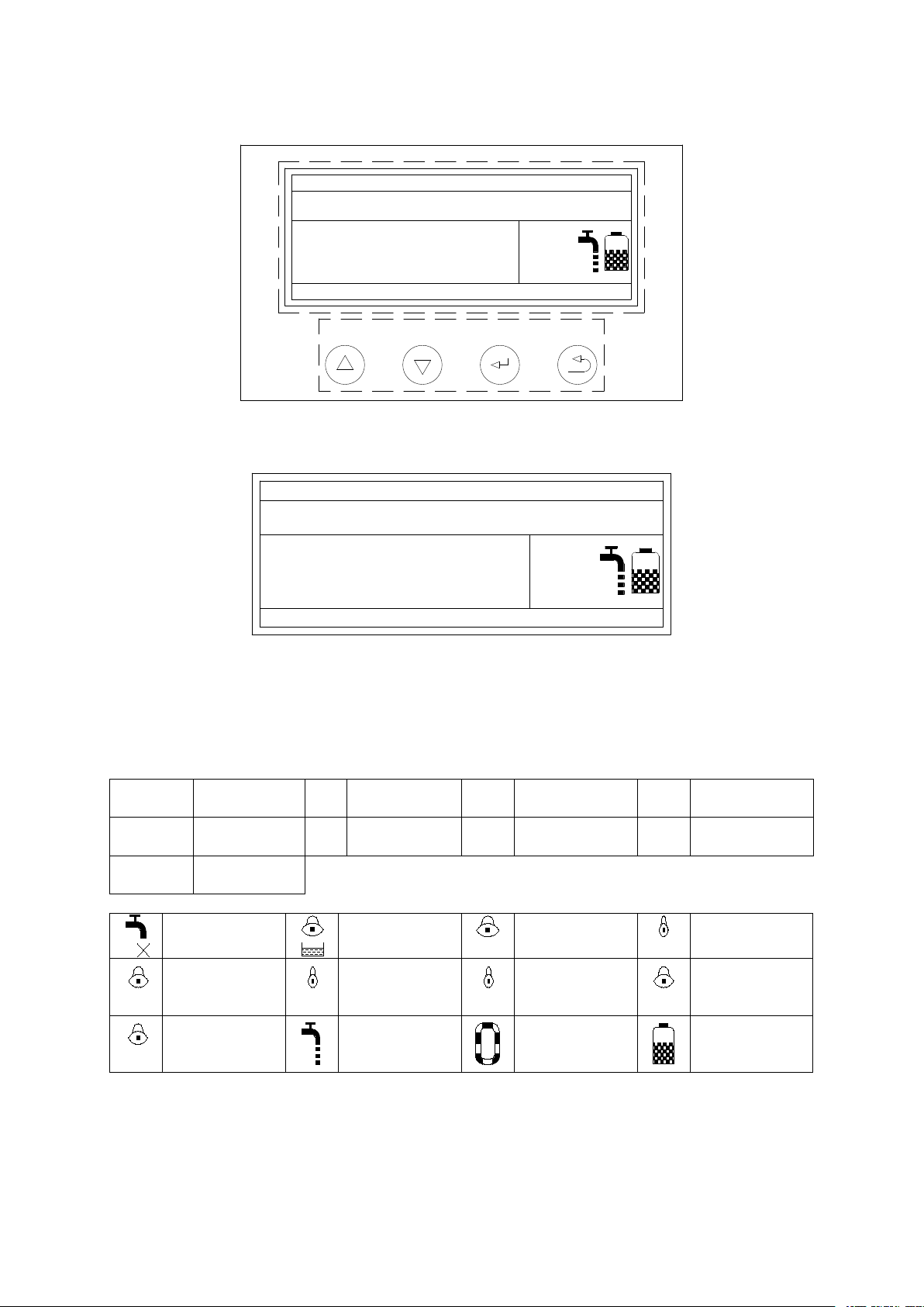
5.2 LCD display area
Smart-NE
Ultra-water Dispensing
25.0°C
08:00 20/09/2016
UP: 18.2 MΩ·cm
Vol Disp: OFF
A: system model and the current temperature display .
B: current status
C: product water quality and Volume dispense status.
D: date and feed water conductivity.
E: graphic for display status.
5.3 Symbols and graphics for LCD display
symbols
FEED
Feed water
conductivity
RO
Pure water
conductivity
UP
Products
resistivity
DS
deionization
rate
PF
Pretreatment
cartridge
UF
Ultra-filter
UV
UV lamp
Vol.
Disp
Fixed Volume
Dispensing
EDI
EDI water
resistivity
graphics
Without feed
water
System
leakage
FE
Feed water
low quality
PF
Pretreatment
failure
RO
RO failure
UF
Ultra-filter
failure
UV
UV light failure
DI
Purification
cartridge
failure
DS
RO failure
Ultrapure
water
producing
Ultrapure
water recycle
Tank level
5.4 Function Keypad
There are 4 function keypads in the system: DISP./▲, Flush/▼, Stop/and Menu/.
DISP./▲
Dispense product water, adjusting keypad at the menu mode.
Flush/▼
Flush cartridges, adjusting keypad at the menu mode.
Stop/
Stop current operation, confirmation keypad at the menu mode.
Menu/
Parameter setting.
A
B
A
B
C
D
E
11
5.5 Operation
Turn on feed water supply. Ensure that all the pipe connecting parts have no leaking. Switch on the
power supply at the back of the main unit.
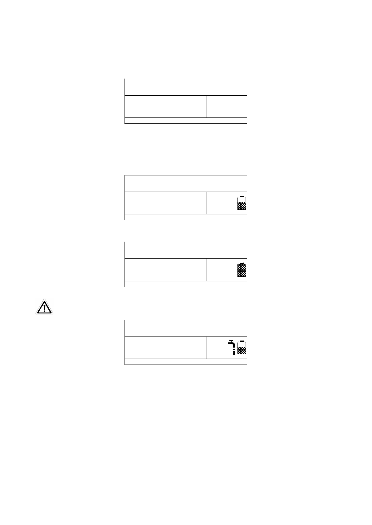
After the main unit is powered on, LCD will display a welcome message, which is followed by the
current state of the system. The system will remain in flushing status about 1 minute.
Smart-NE
System Flushing...
25.0°C
08:00 20/09/2016
1:001:00
The lack of water warning will show in the right of display area when the pressure of feed water is
too low or no feed water. The main unit will stop to standby status. The main unit will re-start to flush
automatically when the water comes again, as shown below:
When the flushing process of main unit is finished, the system will automatically enter the water
producing state. The Smart-NE will flush automatically RO membrane before and after producing EDI
water. The system also shows water conductivity.
Smart-NE
EDI water making
25.0°C
20/09/2016
RO: 10.0 μs/cm
EDI: 15.2 MΩ.cm
FEED: 400μs/cm
When the storage tank of Smart-NE system is full , the system will enter the standby mode
automatically.
Standby
25.0°C
IdealIdeal forfor lablab
08:00 20/09/2016
Smart-NE
Press "Disp. / ▲" keypad you can take the high pure water.
Ensure that the pure water at least 20% of the Smart-NE water tank(water level 1).
Smart-NE
HP-water Dispensing
25.0°C
08:00 20/09/2016
Ideal for lab
Vol Disp: OFF
Press "Stop/" keypad to stopping take product water. The LCD displays the next system state.
Smart-NE has manual flush function for RO membrane cartridge, press the "Flush / ▼" to flush RO
membrane cartridge manually for 1 minute. At this time the LCD display of the main unit is the same as
flushing mode from the beginning.
Press the "Stop / "keypad to stop flushing operation. LCD will display the next current-status.
You can take ultrapure water with the remote water dispenser. If the quality of current ultrapure
water can not meet the requirement of original setting (ie 16.0MΩ.cm), the system will automatically
enter recycling mode to improve the water quality. And if the water quality reaches the set value, the
main unit starts to produce ultra-pure water.
When the Smart-NE system is in the standby state, the ultrapure water in the loop will automatically
recycle for 5 minutes every 2 hours, which will guarantee the quality of ultrapure water to the setting
requirement.

12
Smart-NE
25.0°C
08:00 20/09/2016
Cycling...Cycling...
Standby
5.6 Parameters setting
Press "Menu" keypad to enter the menu
语言 LANGUAGE
ENGLISH
中文
Press "Disp./▲" or "Flush/▼" keypad to select "ENGLISH". Press the "Stop /" keypad to confirm
the setting and to the next level.
Password: 85
Press or hold down the "Disp. / ▲" or "Flush / ▼" keypad to enter the correct password. The default
password is 85. Enter the password, press the "Stop / " keypad to confirm the entry of next menu level.
If the password input is error, the system will be directly reset.
Parameter
setting
Service
setting
Press the "disp. / ▲" "Flush / ▼" keypad to select "Parameter setting". Press the "Stop / " keypad
to enter the parameter setting level
After entering the parameter setting menu, you can see the contents of the setting are: Alarm
settings, Calendar, Product conductivity unit, Volume of water dispense,
AlarmAlarm settingsetting
AlarmAlarm
settingsetting CalenderCalender Prod.Prod.
unitunit
VolumeVolume
ofof waterwater Prod.Prod.
Resis.Resis. Disp.Disp.
flowflow
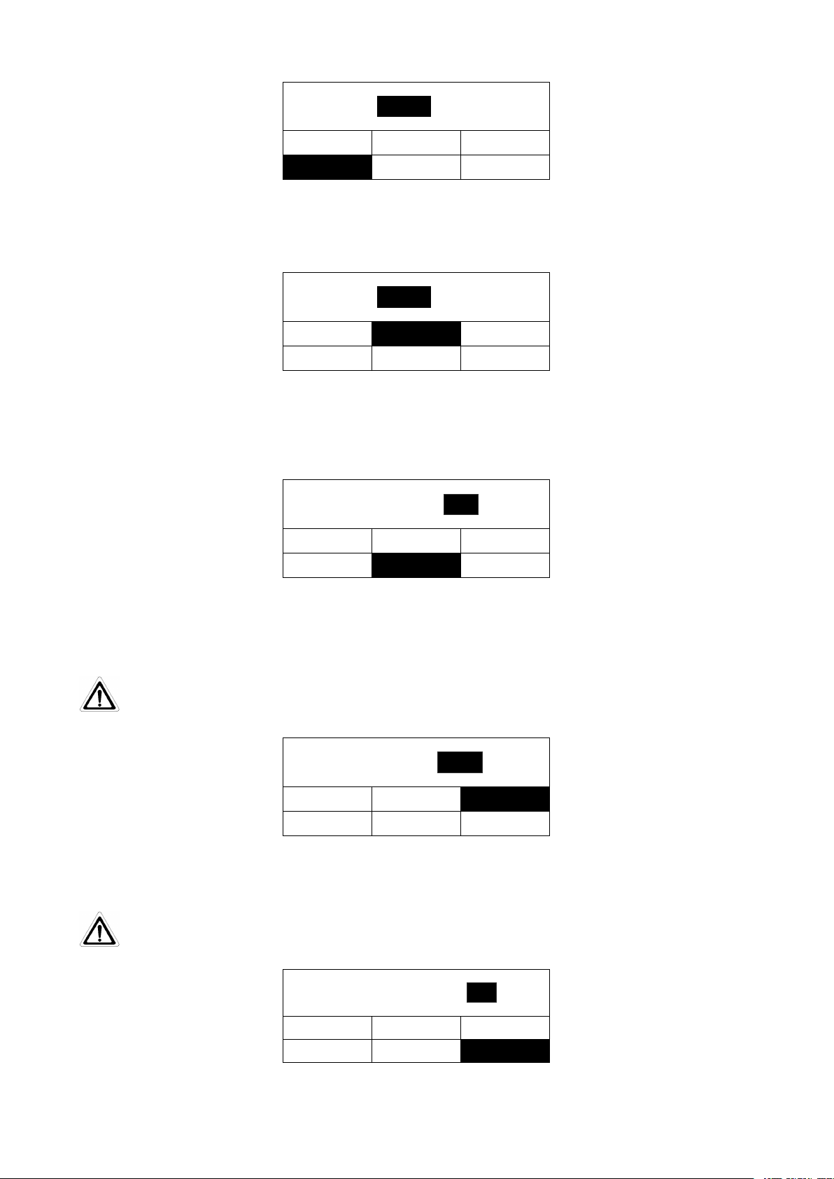
5.6.1 Alarm Settings
After entering the parameter setting menu, press the "Disp. / ▲" or "Flush / ▼" keypad to select
"Alarm setting". Press the "Stop / " keypad to confirm the settings menu to enter the alarm category
including various settings.
UFUF lifelife
UVUV lifelife FeedFeed
RORO
DSDS
PFPF
lifelife : 400h400h 500h500h 600h600h
PFPF lifelife
Alarm time setting for pretreatment failure
In this menu level the maintenance interval for the pre-treatment cartridge ,it must be reset after
exchanged ,the manufacture setting is 400 hour, the user can press “Disp./▲,Flush/▼” keypad to select
one of the 400,500,600hour according to the tap water quality. Press the “Stop/” keypad to confirms the
setting and switches to the next menu level.
Select alarm time UV lamp failure
13
UVUV lifelife
PFPF lifelife UFUF lifelife
FeedFeed
RORO
DSDS
UVUV
lifelife : 6000h6000h 8000h8000h
4000h4000h
In this menu level the maintenance interval for the UV oxidator of main system must be reset after
exchanging the UV lamp. the manufacture setting is 4000hour for UV lamp life time, the user can press
“Disp./▲,Flush/▼” keypad to select one of the 4000,5000,6000,hour according to the user desire. Press
the “Stop/” keypad to confirms the setting and switches to the next menu level.
Micro-filter failure time alarm options
UVUV lifelife
PFPF lifelife UFUF lifelife
FeedFeed
RORO
DSDS
UFUF
lifelife : 6000h6000h 8000h8000h
4000h4000h
In this menu level the maintenance interval for the Micro-filter Cartridge life time of main system
must be reset after exchanging the cartridge. the manufacture setting is 4000hour for Micro-filter
Cartridge life time, the user can press “Disp./▲,Flush/▼” keypad to select one of the 4000,5000,6000
hour according to the user de sire. Press the “Stop/” keypad to confirms the setting and switches to the
next menu level.
Feed water quality alarm setting
PFPF lifelife UFUF lifelife RORO
DSDS
FeedFeed WaterWater
Alarm-HAlarm-H :
UVUV lifelife
μs/cmμs/cm
400400
FeedFeed
The limit of the feed tap water conductivity can be adjusted by the user. If the adjusted limit will be
overstepped it will decrease the life time of Pre-treatment cartridge, RO membrane and purification
cartridge. the manufacture setting is 400us/cm, the user can press “Disp./▲,Flush/▼” keypad to
adjusting according to the user desire. Press the “Stop/” keypad to confirms the setting and switches to
the next menu level.
When setting the value, please refer to the actual water quality. Only to eliminate the alarm for
feed water. If the feed water quality is poor, the overall performance and lifetime of each
module will be affected.
Pure water quality alarm settings
PFPF lifelife UFUF lifelife
FeedFeed DSDS
RORO
Alarm-HAlarm-H :
UVUV lifelife
μs/cμs/c
RORO
20.020.0
The limit of the RO water conductivity can be adjusted by the user. if the adjusted limit will be
overstepped it will decrease the life time of purification cartridge. the manufacture setting is 20us/cm, the
user can press “Disp./▲,Flush/▼” keypad to adjusting according to the user desire. Press the “Stop/”
keypad to confirms the setting and switches to the next menu level
If this value is set too large, then the performance and lifetime of the ultrapure water purification
cartridge will be affected.
Alarm settings for reverse osmosis desalting rate
PFPF lifelife UFUF lifelife
FeedFeed
RORO
DSDS
Alarm-LAlarm-L :
UVUV lifelife
%
DSDS
9090
The limit of the desalting rate of the RO membrane can be adjusted by the user. The display of the

14
system shows the alarm message “Ds light” if the adjusted limit will be overstepped (manufacture’s
setting is 90%). press “Disp./▲,Flush/▼”keypad to increases or decreases the value, press the Stop/”
keypad to confirm the setting and switches to the next menu level.
This value should not be set too low, otherwise the pure water quality will be affected. If the quality
of inlet water is too poor, Please set high value for higher pure water requirement. Value setting range:
50 to 99.
5.6.2 Calendar setting
After entering the parameter setting menu, press “Disp./▲” or “Flush/▼”keypad to select the
"Calendar" function.
CalenderCalender
AlarmAlarm
settingsetting CalenderCalender Prod.Prod.
unitunit
VolumeVolume
ofof waterwater Prod.Prod.
Resis.Resis. Disp.Disp.
flowflow
In this menu level the user want to change the timer in maim system ,you can be press the
“Disp./▲,Flush/▼”keypad to set the correct date and time according to the mention of the display. Press
the “Stop /” keypad to confirms the setting and switches to the next menu level.
YearYear
MonthMonth
9
HourHour
1212 MinuteMinute
3030
DateDate
2020
20162016
YearYear
20162016
5.6.3 Volume of taking product water setting
After entering the parameter setting menu , press “Disp./▲” or “Flush/▼”keypad to select the
"Volume of water" function.
VolumeVolume ofof waterwater
AlarmAlarm
settingsetting CalenderCalender Prod.Prod.
unitunit
VolumeVolume
ofof waterwater Prod.Prod.
Resis.Resis. Disp.Disp.
flowflow
Press "Stop / " keypad to enter the volume of taking water setting interface.
AlarmAlarm
settingsetting CalenderCalender Prod.Prod.
unitunit
VolumeVolume
ofof waterwater Prod.Prod.
Resis.Resis. Disp.Disp.
flowflow
Volume:Volume: OFFOFF
In this menu level the user can be adjusted fixed quantity of take water from 0.1L to 25L, or No
limit(off) , the manufacture setting is No limit(OFF), the user can press “Disp./▲,Flush/▼” keypad to
adjusting according to the user desire. Press the “Stop/” keypad to confirms the setting and switches to
the next menu level
5.6.4 Dispensing flow setting
By setting this parameter, user can calibration the accuracy of fixed quantity of taking water such as
1L or 5L.
After entering the parameter setting menu ,Press the “Disp./▲”or “Flush/▼”keypad to select the
"Dispense flow" function.
DispensingDispensing flowflow
AlarmAlarm
settingsetting CalenderCalender Prod.Prod.
unitunit
VolumeVolume
ofof waterwater Prod.Prod.
Resis.Resis. Disp.Disp.
flowflow
Press the “Stop/” keypad to confirms the setting and switches to the next menu level.

15
AlarmAlarm
settingsetting CalenderCalender Prod.Prod.
unitunit
VolumeVolume
ofof waterwater Prod.Prod.
Resis.Resis. Disp.Disp.
flowflow
DispensingDispensing
flowflow : L/mL/m
1.501.50
Note: Suggestion the user had batter to calibrating fixed quantity every half month.
5.6.5 Ultra-pure water quality setting
After entering the parameter setting menu according to this chapter, press “Disp./▲”or
“Flush/▼”keypad to select the "Prod. Resis." function.
ProductProduct resistivityresistivity
AlarmAlarm
settingsetting CalenderCalender Prod.Prod.
unitunit
VolumeVolume
ofof waterwater Prod.Prod.
Resis.Resis. Disp.Disp.
flowflow
Press “Stop/”keypad to enter the water quality parameters setting interface.
AlarmAlarm
settingsetting CalenderCalender Prod.Prod.
unitunit
VolumeVolume
ofof waterwater Prod.Prod.
Resis.Resis. Disp.Disp.
flowflow
Prod.Prod.
Resis.Resis. : MΩMΩ·cmcm
16.016.0
The limit of the resistivity of the ultra pure water from purification cartridge can be adjusted by the
user. the manufacture setting is 16.00MΩ.cm, if the resistivity of product water is lower than limit ,the
product water will be recycling in main system , the product water ‘s resistivity of user’ taken is higher
than the limit. the user can press “Disp./▲,Flush/▼” keypad to adjusting according to the user desire.
Press the “Stop/” keypad to confirms the setting and switches to the next menu level.
5.6.6 Unit selection
By setting this parameter, user can choose to the unit form of the ultrapure water, MΩ.cm or μS/cm.
After entering the parameter setting menu according to this chapter, press “Disp./▲”or
“Flush/▼”keypad to select the "Prod. Unit." function.
ProductProduct unitunit
AlarmAlarm
settingsetting CalenderCalender Prod.Prod.
unitunit
VolumeVolume
ofof waterwater Prod.Prod.
Resis.Resis. Disp.Disp.
flowflow
Press "Stop / " button to confirm the unit selection interface.
AlarmAlarm
settingsetting CalenderCalender Prod.Prod.
unitunit
VolumeVolume
ofof waterwater Prod.Prod.
Resis.Resis. Disp.Disp.
flowflow
Prod.Prod.
unitunit : μs/cmμs/cm
MΩ·cmcm
In this menu level the user can select the display unit of product water , the user can press
“Disp./▲,Flush/▼” keypad to selecting one of “MΩ.cm” “or us/cm” according to the user desire. Press
the “Stop/Enter” keypad to confirms the setting and switches to the next menu level.
Table of contents
Other Heal Force Water Filtration System manuals

Popular Water Filtration System manuals by other brands


Pentair
Pentair EZ-RO 200/2G-BL Installation & operation guide

PureEffect
PureEffect ULTRA-WHW installation instructions

Simple Water Service
Simple Water Service 7QCRO Installation, operation & service

Weller
Weller Zero Smog TL Translation of the original instructions

Sterling
Sterling OXY3 Series Installation instructions and owner's manual

AAF
AAF TM4 Installation, operation and maintanance instructions