8Fuel Conversion Kit Instructions • 54D0704 Rev. A • 04/17
Bench Testing Engine / Burner Assembly
Millivolt Models:
1. Attach ex connector. Turn on the gas shut off valve.
Turn the control knob to the “PILOT” position only.
Figure 9
2. Light the pilot. Use soapy water to check for leaks on
the pilot assembly and regulator.
3. Turn control knob to “ON” position following the light-
ing instructions in owner’s manual. Use soapy water to check for leaks around
tting of aluminum tubing. Light burner. Figure 10
4. Place the Propane Conversion rating label plate and the regulator’s conver-
sion label on the existing rating plates. Refer to Figure 6 for rating plate and
conversion label locations. Attach conversion label to control valve.
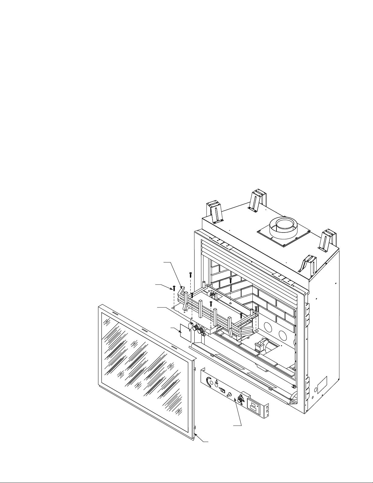
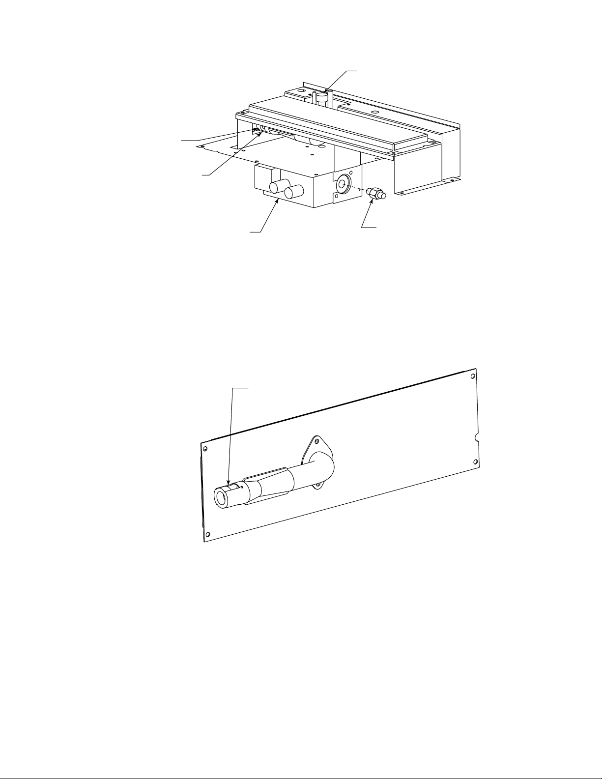
5. Reinstall engine/burner system assembly. Make sure the gasket provides a
good seal. Reattach the ignitor and on/off switch wires. Reattach valve cover/
faceplate.
6. Reattach the union. Open the gas shut off valve. Check the connection for
leaks using a soapy water solution.
7. Reinstall logs, grate and embers. Refer to Owner’s Manual
8. Reinstall glass door.
9. Light unit. Check for proper burner ame appearance. Refer to Owner’s Manu-
al.
Electronic Models
1. Attach ex connector. Turn on the gas shut off valve.
2. Turn RS-OFF-ON rocker switch to “ON” position.
3. Check for leaks around pilot, regulator and tting of aluminum tubing with soapy
water. Turn off burner.
4. Place the Propane Conversion rating plate and the regulator conversion label
on the existing rating plates. Refer to Figure 6 for rating plate and conversion
label locations. Attach conversion label to control valve.
5. Reinstall engine/burner system assembly. Make sure the gasket provides a good seal. Reattach
the ignitor and on/off switch wires. Reattach valve cover/faceplate.
6. Reattach the union. Open the gas shut off valve. Check the connection for leaks using a soapy
water solution.
7. Reinstall logs, grate and embers. Refer to Owner’s Manual
8. Reinstall glass door.
9. Light unit. Check for proper burner ame appearance. Refer to Owner’s Manual
DANGER
Never check for gas leak with open
ame!
TOLIP
O
F
F
P
I
L
O
T
O
N
FP1935
control knob pilot
Figure 9
Valve Control - “PILOT” Position
FP1935
O
F
F
P
I
L
O
T
O
N
TOLIP
FP1937
control knob on
Figure 10
Valve Control - “ON” Position
FP1937
Hearth & Home Technologies
7571 215th Street West, Lakeville, MN 50044
www.hearthnhome.com