28 Heat & Glo • VRTIKL-AU • 2123-900 • 7/07
B. Lighting the Appliance
Electronic Ignition
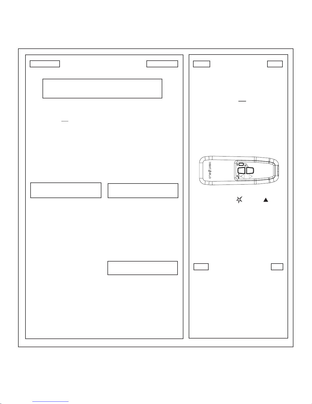
LIGHTING
INSTRUCTIONS
TO TURN OFF
GAS TO HEATER
1. Push the ‘OFF’ button on remote.
2. Remove batteries from receiver.
FOR YOUR SAFETY
READ BEFORE LIGHTING
WARNING: If you do not follow these instructions
exactly, a fire or explosion may result causing property
damage, personal injury or loss of life.
A. This heater is equipped with an
electronic pilot ignition device
which automatically lights the
burner. Do not try to light the
burner by hand.
B. BEFORE LIGHTING, smell all
around the heater area for gas.
Be sure to smell next to the floor
becausesome gas is heavierthan
air and will settle on the floor.
WHAT TO DO IF YOU SMELL
GAS
• Do not try to light any appliance.
Improper installation, adjustment,
alteration, service or maintenance
can cause injury or property dam-
age.Refertotheowner’s information
manual provided with this fireplace.
This heater needs fresh air for safe
operation and must be installed so
there are provisions for adequate
combustion and ventilation air.
If not installed, operated, and main-
tained in accordance with the man-
ufacturer’s instructions, this product
could expose you to substances in
fuel or fuel combustion.
Keep burner and control compart-
ment clean. See installation and
operating instructions accompany-
ing heater.
CAUTION:
Hotwhilein operation. Do nottouch.
Keep children, clothing, furniture,
gasoline and other liquids having
flammable vapors away.
Do not operate the heater with
panel(s) removed, cracked or bro-
ken. Replacement of the panel(s)
should be done by a licensed or
qualified service person.
• Donottouchanyelectric switch; do
not use any phone in your building.
• Immediately call your gas supplier
from a neighbor’s phone. Follow
the gas supplier’s instructions.
• If you cannot reach your gas sup-
plier, call the fire department.
C. Do not use this fireplace if any part
hasbeenunderwater.Immediately
callaqualifiedservicetechnicianto
inspect the heater and to replace
any part of the control system and
any gas control which has been
under water.
NOT FOR USE
WITH SOLID FUEL
For use with natural or propane
gases.
WARNING:
1. This heater is equipped with an igni-
tion device which automatically lights
the burner. Do not try to light the
burner by hand.
2. Wait five (5) minutes to clear out any
gas. Then smell for gas, including
nearthefloor.If yousmell gas,STOP!
Follow “B” in the Safety Information
located on the left side of this page. If
you don’t smell gas, go to next step.
3. To light the burner, simultaneously
press the star and up arrow
buttons on the remote control until a
shortacoustic signalconfirmsthe start
sequence has begun.
4. Iftheheaterwillnot operate,check the
batteries then follow the instructions
“To Turn Off Gas to Heater” and call
your service technician or gas sup-
plier.