Heat Electric Conservatory Radiator 3100 User manual

Revision
0501M077.H
Date
08/08/2012
Heat Electric Radiators
Installation and Operating Instructions
INSTALLER PLEASE NOTE:
LEAVE INSTALLATION AND OPERATING INSTRUCTIONS WITH CUSTOMER

Page 2
Document
Heat Electric - Operator
Revision
0501M077.H
Date
08/08/2012
INSTALLATION AND OPERATION

1.0 Contents Page
1.0 Contents 3
2.0 This manual covers the following models 4
3.0 Important Health and Safety Information 5
4.0 Installation Instructions 7
4.1 Positioning 7
4.2 Fitting 8
5.0 Operating Instructions 10
5.1 Before Switching On 10
5.2 Switching On 10
5.3 Manual Operation 11
5.4 24 Hour Timer 11
5.5 Setting the Heating Times 12
5.6 Overriding the Timer 12
6.0 Radio Frequency Control Options (RFC1 and RFC3) 13
6.1 Batteries 13
6.2 Connecting your Radiator to your Controller 13
6.3 Choosing a position in the room 14
6.4 Range Test 14
6.5 Fixing the RFC to the Wall 14
6.6 Reverting your Radiator to Manual Control 15
6.7 Choosing a new ID 15
6.8 Frost Protection 15
6.9 Cleaning 16
7.0 Your RFC1 Unit. 17
7.1 Setting the Time and Day 18
7.2 Factory set Program 18
7.3 Frost Protection 4°C 18
7.4 Celsius or Fahrenheit 18
7.5 Setting the 7 day program 19
8.0 Your RFC3 Unit 21
8.1 Setting the Time and Day 21
8.2 Factory Set Program 22
8.3 Altering the Factory Set Program 23
8.4 User Adjustment 23
9.0 Trouble Shooting Guide 25
10.0 After Sales Service 26
Page 3
Document
Heat Electric - Operator
Revision
0501M077.H
Date
08/08/2012
Page 4
Document
Heat Electric - Operator
Revision
0501M077.H
Date
08/08/2012
INSTALLATION AND OPERATION
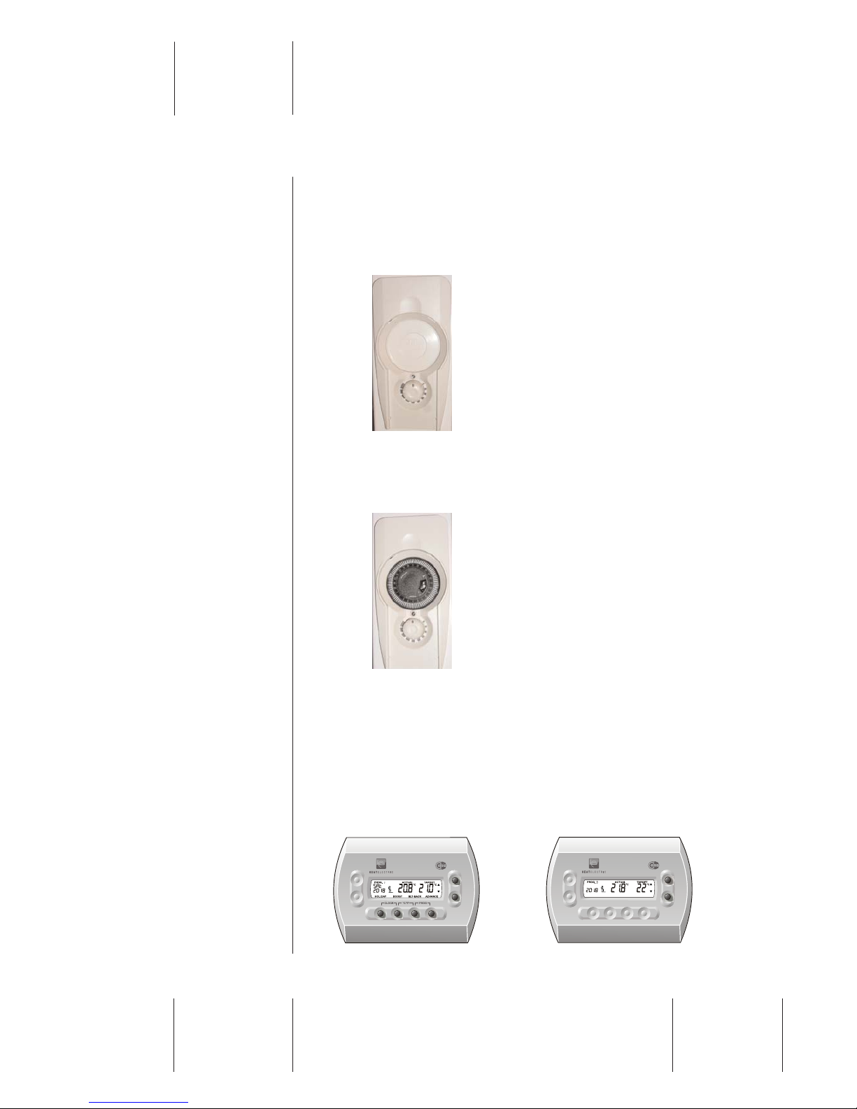
2.0 This manual covers the following models
Radio Frequency Enabled
The radio frequency enabled model contains a dial temperature setting,
tamper proof cover and a hidden air sensing thermostat, allowing for simple
to use heat control. The radiator can be used with an optional wireless
Radio Frequency controller.
Timer
The timer model features a 24 hour segment timer to allow easy heat and
time programming, a dial temperature setting, tamper proof cover and a
hidden air sensing thermostat.
Radio Frequency Control Options
The Radio Frequency controllers are an optional extra for the radio
frequency enabled model. They provide wireless, 7-day, 24 hour digital
thermostat which ensure the maximum level of energy efficient heating. The
controller also allows for six different temperature settings per day and can
program several radiators as a group. Installing more than one controller
within a home allows for zoned controllability. They can be wall mounted,
are battery powered and display the current and target room temperatures.
RFC1 RFC3

Page 5
Document
Heat Electric - Operator
Revision
0501M077.H
Date
08/08/2012
3.0 Important Health and Safety Information
In normal operation SURFACES OF THE RADIATOR CAN BECOME HOT
AND CONTACT WITH THESE AREAS SHOULD BE AVOIDED. If young
children, the aged, or infirm are likely to be left unsupervised in the vicinity
of the radiator, we advise that adequate precautions should be taken. We
recommend that a guard be used to ensure that contact with the radiator is
not possible. An LST (Low Surface Temperature ) cover is available to solve
this problem.
The RF controlled radiator is a “class I” IP44 device and it can be installed
in bathrooms zone 2 and 3 provided that no electric control unit can be
touched by people using the bath-tub or the shower. If the radiator is
installed in zone 2 or zone 3 it must be wired into a fused spur located in
the appropriate zone.
The timer radiator is IP20 compliant and can be fitted in Zone 3.
Warning
Both the RF controlled and timer radiators must not come in
direct contact with water. This includes excessive humidity or
using wet hands to operate the controls.

Page 6
Document
Heat Electric - Operator
Revision
0501M077.H
Date
08/08/2012
INSTALLATION AND OPERATION
WARNING! – The radiator must not be located immediately below or in front
of an electrical socket outlet.
WARNING! – The radiator must only be operated in the upright position and
fitted to the wall with the fixing brackets supplied.
Ensure that the mains lead is properly secured to avoid trip hazards.
DO NOT operate the radiator with the mains lead overhanging the radiator.
DO NOT FULLY COVER THE RADIATOR or place material or garments on
it. Do not obstruct the air circulation around the radiator, for example with
curtains or furniture.
Supply Voltage – 230-240VAC 50Hz
WARNING – THIS APPLIANCE MUST BE EARTHED.
This radiator must be used on an AC supply only, and the voltage marked
on the radiator must correspond with the supply voltage.
Installation must be in accordance with the requirements of the current
edition of the IEE Wiring Regulations 16th Edition.
Supply
This radiator must be plugged into a switched socket or wired into a fused
spur. If wiring into a fused spur remove the plug and dispose of safely. (If
installing in France please ensure the radiator is wired into a fused spur
only.)
Supply cord
This radiator is fitted with a moulded plug incorporating a 13 amp fuse. Any
replacement fuses must be approved by BSI to BS 1363. If the supply cord
is damaged, it must be replaced by the manufacturer, its service agent, or
similarly qualified persons in order to avoid a hazard.
Page 7
Document
Heat Electric - Operator
Revision
0501M077.H
Date
08/08/2012
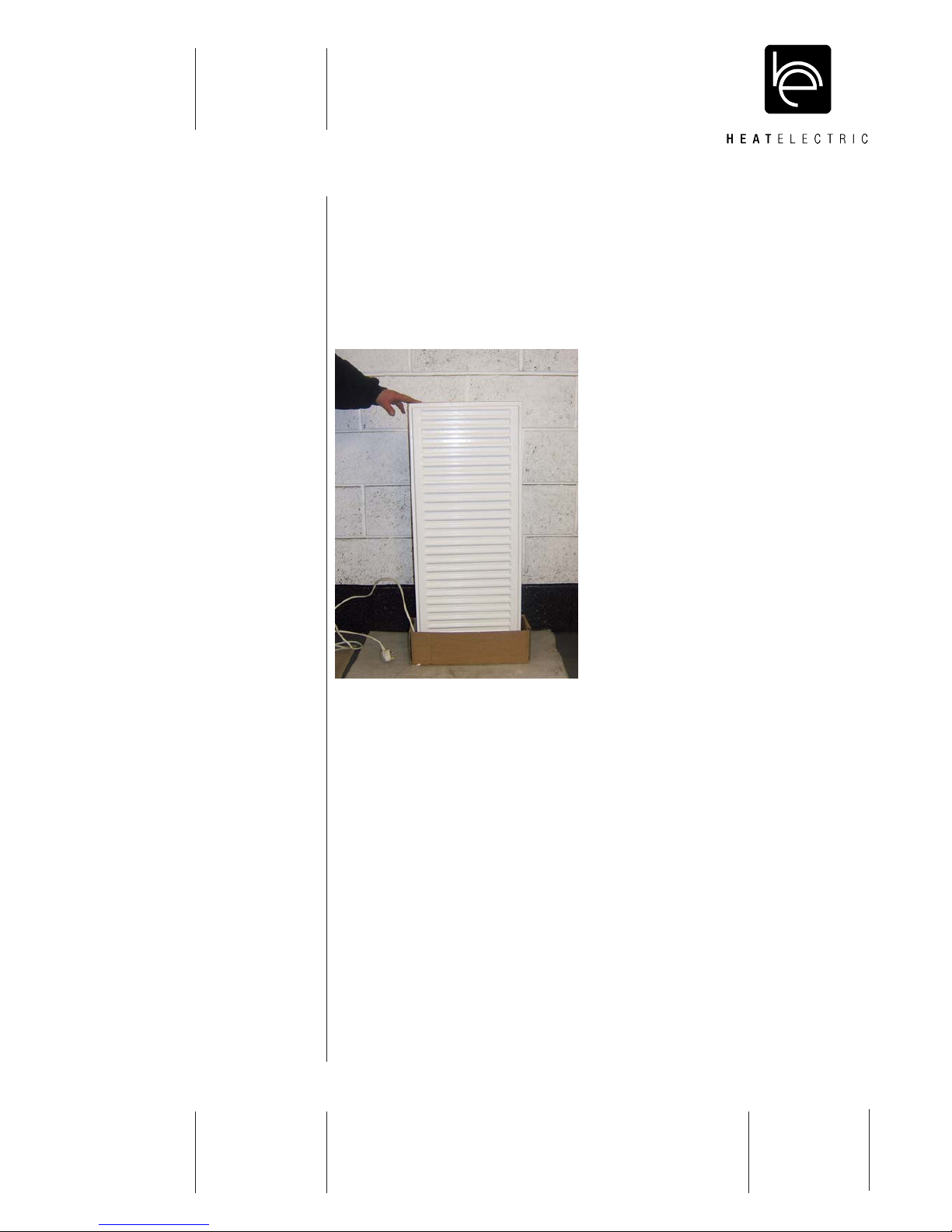
4.0 Radiator Installation Instructions
During transit the fluids contained in this radiator may have moved from
important sensing positions.
To ensure reliable operation, the radiator should be carefully stood on one
of its cardboard endcaps, with the control panel facing down, for thirty
minutes prior to installation.
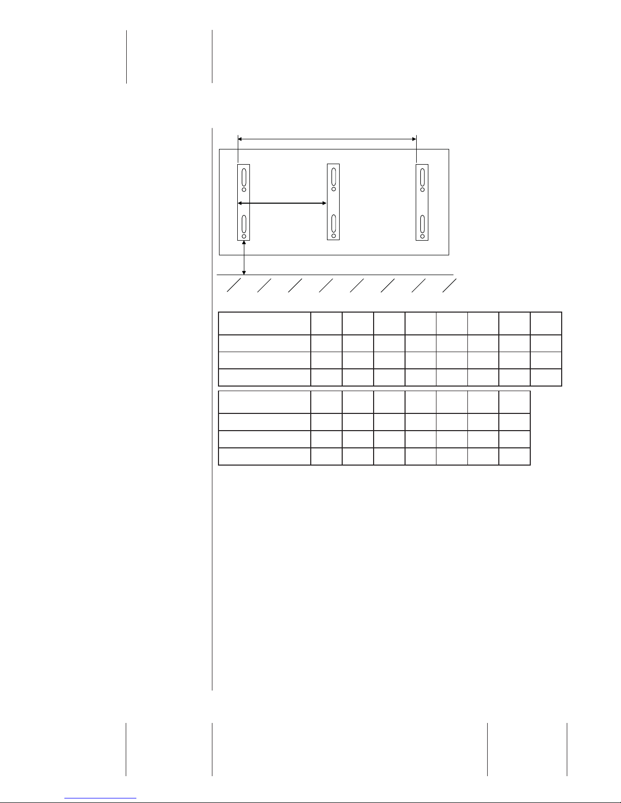
4.1 Positioning
A suitable position for the radiator should be chosen, and the positions of
the mounting brackets marked on the wall, using the dimensions given
below.
For optimum output, the bottom of the radiator should be 150mm from the
floor. Any shelf or substantial projection should be a recommended
minimum of 150mm above the top of the radiator.
Page 8
Document
Heat Electric - Operator
Revision
0501M077.H
Date
08/08/2012
INSTALLATION AND OPERATION
4.1 Fitting
Ensure that the brackets are fitted towards the outside of the hangers on the
radiator. This will prevent any lateral movement when the radiator is
mounted.
To install the radiator at the recommended minimum height, the bottom of
the wall fixing bracket should be approximately 200mm from the floor (see
diagram and table above). To allow for other heights above the floor, note
that the bottom of the fixing bracket is approximately 50mm above the
bottom of the radiator.
For most efficient operation of the radiator, there should be a gap between
the skirting board and the rear panel of the radiator to allow air flow behind
the radiator. If the bottom of the radiator is below the top of the skirting
board, it may be necessary to remove a section of skirting for this purpose.
A
A*
Note: * dimensions for additional bracket for radiators 2000mm long only.
200mm recommended, 150mm min
Model 3100 3140 3160 3200 4100 4140 4160 4200
Bracket Width (mm) 800 1200 1400 1800 800 1200 1400 1800
A* (mm) - - - 900 - - - 900
Weight (kg) 25 33 35 45 33 44 50 61
Model 6040 6060 6080 6100 6120 6140 6160
Bracket Width (mm) 200 400 600 800 1000 1200 1400
A* (mm) - - - - - - -
Weight (kg) 25 29 40 50 58 65 70
Page 9
Document
Heat Electric - Operator
Revision
0501M077.H
Date
08/08/2012
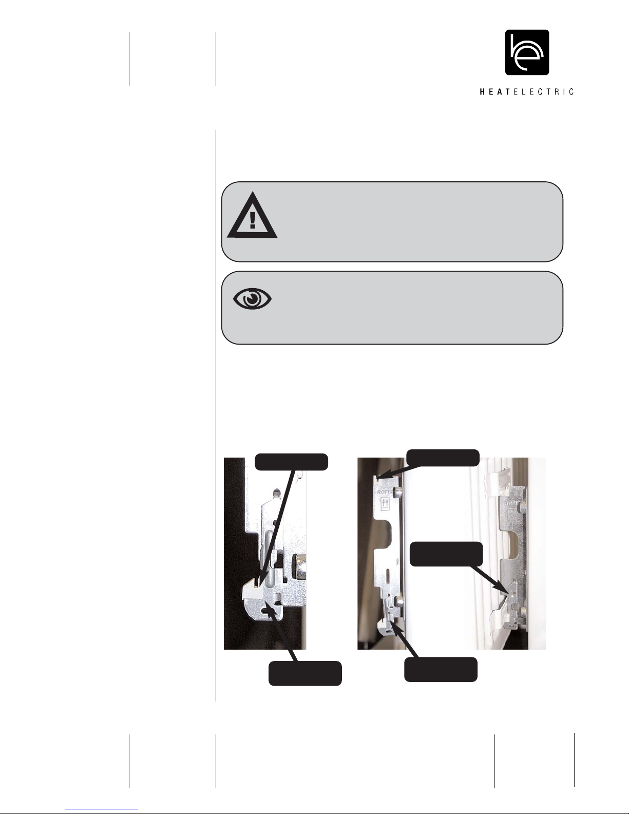
Place the bracket vertically against the wall at the appropriate height, and
to suit the length of the radiator. Mark the positions of the fixing holes on the
wall.
Insert the plastic grommets (A) onto the brackets (these minimise
expansion and contraction noise.) Pull down the spring loaded part of the
bracket (B), and push it back to locate it in its lower position.
Hook the radiator lugs on to the tops of the brackets. Return the spring
loaded part of the bracket (B) to its original position, thereby securing the
bottom of the radiator in its final position.
Caution
Fix the brackets to the wall using fixings appropriate to the
wall material and the weight of the radiator.
The radiators are supplied with wall brackets and fixings.
These fixings may not be suitable for the type of wall fixing.
Warning
When drilling wall, care must be taken to avoid existing wires
and pipes.
A) Plastic Grommet A) Plastic Grommet
B) Catch in raised
position
B) Catch in lowered
position
B) Catch securing
radiator

Page 10
Document
Heat Electric - Operator
Revision
0501M077.H
Date
08/08/2012
INSTALLATION AND OPERATION
5.0 Operating Instructions
5.1 Before Switching On
Ensure that the radiator has been installed correctly and that all warnings
and instructions have been read carefully and followed.
5.2 Switching On
When you are certain that you have completed the above, plug in and
switch on at the wall socket. Switch the power ON, check the supply light is
illuminated ORANGE for a short while then either GREEN or RED
depending on the ambient temperature of the room. This light can be seen
on the control panel.
iNote
This instruction manual should be read carefully and retained
by the user. Particular attention must be made to the health
and safety information at the beginning of this manual.
Warning
DO NOT switch off the radiator at the wall socket when the
radiator is warm.
Note
It is strongly recommended that radiators (all models) are run
for ½ hour each month during the summer to ensure that the
pump is fit for winter operation.

Page 11
Document
Heat Electric - Operator
Revision
0501M077.H
Date
08/08/2012
5.3 Manual Operation
Turn the thermostat knob clockwise to start heating the radiator.
The supply light will show RED when heating up.
As the room thermostat reaches the target temperature the supply light
turns ORANGE. When the ambient air exceeds the desired temperature the
supply light turns GREEN.
The heat demand can be altered using the thermostatic knob. The first time
the radiator is switched on you may hear a slight water rushing noise as the
pump starts, this will only be for a short while, and from then on the radiator
will operate very quietly.
5.4 24 Hour Timer
Setting the Time
The outer dial should be set to the current time. Rotate the dial slowly in a
clockwise direction, until the correct hour is aligned with the arrow printed
on the dial.
The outer dial is printed with
the 24 hour clock:
8:00am = 8 on the dial
8:00pm = 20 on the dial
Do not attempt to rotate the
dial in an anti-clockwise
direction.
Supply Light
Thermostat Knob
24 Hour Timer
5
6
7
8
9
10
11
12
13
14
15
16
17
Current Time

Page 12
Document
Heat Electric - Operator
Revision
0501M077.H
Date
08/08/2012
INSTALLATION AND OPERATION
5.5 Setting the Heating Times
Set all tappets between the on and off times required, to the outer edge of
the dial.
eg. To set on at 8:00 am – Off at 1:00 p.m. push the tappets between dial
numbers 8 and 13 to the outer edge of the dial. Each tappet equates to 15
minutes. Set any other required switching times in a similar manner.
5.6 Overriding the Timer
The manual switch will provide Permanently On / Timed / Permanently Off
control , thereby allowing manual control of the output without disrupting the
timed (tappet) settings.
5
6
7
8
9
10
11
12
13
14
15
16
17
Tappets in ON position
Tappets in OFF position
Permanently ON
Permanently OFF
TIMED - Tappets
Warning
The Permanently ON setting should not be selected for more
than 24 hours at any one time.

Page 13
Document
Heat Electric - Operator
Revision
0501M077.H
Date
08/08/2012
6.0 Radio Frequency Control Options (RFC1 and RFC3)
Radio Frequency Controllers (RFC1 and RFC3) are wireless (433MHz)
thermostats giving high precision room temperature control. They are also
a seven day programmer with up to six temperature settings per day. Each
RFC can control any number of radiators.
The temperature control is primarily set by the RFC. To allow the RFC to
control your radiator fully; the thermostat knob must be turned fully
clockwise. This will allow the RFC to run your radiator at full output if the
need arises. You can however choose a lower radiator setting for systems
where multiple radiators are operated by the same RFC by turning the
thermostat knob anti-clockwise.
6.1 Batteries
Your radio frequency controller is supplied with two factory fitted AA size
alkaline batteries, these should last around two years. The low battery
symbol appears when it is time to replace them. If you don’t replace them
for two weeks the symbol will start to flash. You must reset the clock after
changing the batteries, but all other settings are unaffected.
6.2 Connecting your Radiator to your Controller
For radio control to work, you first need to establish a radio connection
between your radiator and your RFC. You may wish to follow this procedure
if you add more radiators.
1. Turn the radiator thermostat knob fully clockwise.
2. Switch the radiator’s mains supply off.
3. Switch the mains on for about 3 seconds then off again for 3 seconds.
4. Switch the mains on and the radiator supply light will flash.
RFC1 RFC3
Holiday
Button
Boost
Button
Set-Back
Button
Advance
Button
Quick Adjust
Buttons
Note: RFC3 uses Quick Adjust buttons to access all functions

Page 14
Document
Heat Electric - Operator
Revision
0501M077.H
Date
08/08/2012
INSTALLATION AND OPERATION
5. Press the button on the back of the RFC. This will send the connection
signal. The radiator supply light will give a final flash to show that it is
connected.
6. Now that it is connected, you should never have to do this procedure again.
7. If the radiator sees no connection signal for 60 seconds it will return to
normal operation with its connection unaffected.
6.3 Choosing a position in the room.
The RFC should be positioned in a place where its temperature will not be
changed by local events. Avoid:
● Draughty places near windows, doors and vents.
● Places near the radiator or any other heat sources in the room.
● Places in direct sunlight.
● Places where it may get wet.
6.4 Range Test.
Having connected your radiator and chosen a position for the RFC you can
test the wireless connection.
Place or hold your RFC in position. Press BOOST and ADVANCE together
The RFC will transmit a special test
signal every 5 seconds causing the
radiators supply light to flash twice.
In the unlikely event that the radiator
does not respond, check that you have
connected to the radiator. If it still does not work try a different location.
Poor reception can be because :
● The RFC is too far from the radiator.
● There are metal objects (including parts of the building) obstructing
the signal path. Metal objects can also cause reflections that can
interfere with signal strength.
● There are other 433Hz transmissions nearby. This should not be a
problem as all such devices may transmit occasionally and for short
periods of time.
● The range test lasts for 10 minutes or until you press CLEAR.
6.5 Fixing the RFC to the Wall.
Remove the wall plate from the rear of the RFC. Mark wall through the
screw holes (60mm centres). Use the correct type of fitting for the wall and
mount the wall using no. 6 or 8 screws. Clip the RFC onto the wall plate.

Page 15
Document
Heat Electric - Operator
Revision
0501M077.H
Date
08/08/2012
6.6 Reverting your Radiator to Manual Control.
If for any reason you want to use your radiator without the RFC, you can
revert to Manual Control.
● If the radiator is on, switch the mains supply off and turn the
thermostat knob to maximum.
● Switch it on for 3 seconds then switch it off again.
● Repeat this process another 5 times.
● The supply light will flash for 50 seconds and your radiator will be
back to manual control.
6.7 Choosing a new ID
Every RFC has an identifying code . When you connect a radiator you are
teaching the radiator to listen for the RFC’s code. If your radiator switches
on and off when it should not, it may be that another RFC in the vicinity has
the same code. This is very unlikely since there are many thousands of
possible codes.
To make the RFC pick a new random code, hold the button on the back of
the controller on for 5 seconds until the display says “rE5 id” , then press
OK to confirm within 5 seconds. If you don’t confirm no action is taken.
After selecting a new ID you must re-connect your radiator(s).
6.8 Frost Protection
If used with the RF controller, the controller can be used to set the radiator
to the frost protection mode. Ensure the thermostat knob is not turned off.
Note
If the radiator does not heat up when the RF controller is on
a low setting, this is normally because the room is warmer
than the temperature selected on the controller, and is not
due to a fault in the radiator. If the room temperature falls
below that selected on the thermostat knob, the radiator will
then warm up to bring the room temperature to the selected
level.

Page 16
Document
Heat Electric - Operator
Revision
0501M077.H
Date
08/08/2012
INSTALLATION AND OPERATION
6.9 Cleaning
Do not use detergents, abrasive cleaners, or polish on the radiator as these
may damage the finish.
Wipe the radiator with a dry cloth to remove dust and marks.
Warning
Always disconnect from the power supply and allow the
radiator to cool before cleaning.
Note
Only external cleaning is permitted.

Page 17
Document
Heat Electric - Operator
Revision
0501M077.H
Date
08/08/2012
7.0 Your RFC1 Unit.
Quick
Adjust
Buttons
Time, Dayand Program
Here you can see the
current time and day of the
week. PROG shows which
setting the controller is
currently on.
Holiday (No Program)
Pressing HOLIDAY
switches heating to 4°C to
12°C (frost protection) or it
remains at ‘no heating’ if it
was previously showing - - -
It stays like this until you
press CLEAR.
Boost (Full Power)
Press BOOST to turn the
radiator on full power for an
hour. If you press BOOST
ag ain it adds another hour up
to a maximum of 4 hours.
You can use and to
adjust the minutes.
Boost ends when the timer
runs out or you can cancel it
by pressing CLEAR.
Power Level
As your room reaches the
target temperature the
power of your radiator is
reduced from 100% to 0%
when no bars are shown.
Actual / Target Temp
Actual is a thermometer
showing the actual room
temperature. Target is the
temperature you would like.
It is set manually or by the
program and can be - - -
when no heating is needed.
Quick Adj ust
During normal operation
you can use and to
alter the temperature.
The effect is temporary; it
reverts to normal
temperature on the next
prog or when you press
other buttons. You can set it
to - - - (no heating), 4°C
(frost protection) or
anything from 4°C to 30°C.
The and buttons are
used to adjust other things
when you are setting the
program or the clock.
Adv an ce ( Early Bird)
Press ADVANCE if you
wish to bring forward the
next program;for instance if
you arrive in or leave a
room earlier than normal.
The program stays
advanced until the
program’s normal time or
until you press CLEAR.
Set-Back ( Economy)
For economy press SET-
BACK. The 7 day program
continues to run but all
temperatures (except frost)
are lowered by 5°C. Set-
Back continues until you
press CLEAR.
Transmit Symbol
You will see the
transmit symbol
whenever the
RFC1 transmits to your
radiator. This happens
about once a minute.
Page 18
Document
Heat Electric - Operator
Revision
0501M077.H
Date
08/08/2012
INSTALLATION AND OPERATION
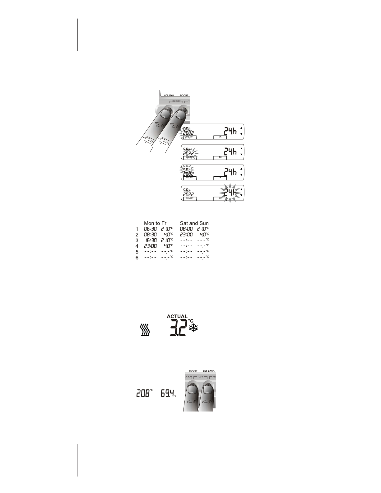
7.1 Setting the Time and Day.
To set the clock press
HOLIDAY and BOOST
together. The hours will start to
flash and you can adjust them
with ▲ and ▼.
Using SELECT you can adjust
minutes, day of week or
change from 24 hour clock to
12 hour clock. When finished
press OK.
7.2 Factory set Program.
On each weekday the target temperature
is 21°C from 6:30am to 8:30am, then 4°C
(frost protection) until 4:30pm, then it is
21°C until 11:00pm and finally 4°C until
PROG.1 the next day.
Press ▲ and ▼ together from Setting the 7 day program to restore this
program.
7.3 Frost Protection 4°C.
For frost protection set the Target
temperature to 4°C. There is no frost
protection if you set it to - - -.The
snowflake symbol appears if the actual
temperature ever falls below 4°C.
7.4 Celsius or Fahrenheit
Pressing BOOST and SET-BACK
together changes Actual and Target
temperature between Celsius and
Fahrenheit.

Page 19
Document
Heat Electric - Operator
Revision
0501M077.H
Date
08/08/2012
7.5 Setting the 7 day program
To set the program press SET-BACK and
ADVANCE together. This will take you to
stage 1 below. You can program the
RFC1 with up to 6 temperature levels per
day.
Program times cannot overlap, for example if PROG.3 Mon is 16:30 then
PROG.3 Mon can only be set to times before 16:30.
Stage 1
The program number and day will flash.
You can change it with ▲ and ▼.
SELECT takes you to stage 2.
Stage 2
The time flashes . You can adjust it with ▲
and ▼. SELECT takes you to stage 3.
Stage 3
The temperature flashes . You can adjust
it with ▲ and ▼ for room temperature,
4°C (frost protection) or --- (no heating).
SELECT takes you to stage 1.
Stage 4
When you have finished setting the program press OK to return to normal
operation.
Clearing a Program
If you clear a prog it displays as --:--,--.--
°C and the program is ignored.
From Stage 1 press CLEAR to clear a
prog and press it again to un-clear it.

Page 20
Document
Heat Electric - Operator
Revision
0501M077.H
Date
08/08/2012
INSTALLATION AND OPERATION
Copy Day
Use this to copy all 6 programs from the
day you were adjusting to another day.
Press COPY DAY to actually do the copy.
CLEAR returns to stage 1
Manual Operation
If you clear all 6 programs in all 7 days, there is no program at all.
The temperature control is done entirely by Quick Adjust.
This manual suits for next models
14
Table of contents
Popular Heater manuals by other brands

Menuett
Menuett 014421 operating instructions

Orion
Orion OOR-009TT instruction manual

AMIRIDIS-SAVVIDIS
AMIRIDIS-SAVVIDIS UNITED ARH-8509 operating instructions

ElectrIQ
ElectrIQ DPHW1500W user manual

Suntec Wellness
Suntec Wellness Air Booster Design 2000 manual

VOLTOMAT HEATING
VOLTOMAT HEATING FH-111907.1 instruction manual


