HEAT GLO Radius Series User manual

Radius
Series Wood Stoves
Australian Owner's Manual • Installation and Operation
HEAT GLO.
No one builds a better fire
NOTE: This product is designed as an intermittent wood burner and not intended to be used as a primary heat source

and Welcome to the Heat & Glo Family!
Hearth & Home Technologies welcomes you to our tradition
of excellence! In choosing a Heat & Glo appliance, you
have our assurance of commitment to quality, durability,
and performance.
This commitment begins with our research of the market,
including 'Voice of the Customer' contacts, ensuring we
make products that will satisfy your needs. Our Research
and Development facility then employs the world's most
advanced technology to achieve the optimum operation of
Serial Rating Plate Example
our stoves, inserts and fireplaces. And yet we are old-fash-
ioned when it comes to craftsmanship. Each unit is meticu-
lously fabricated and surfaces are hand-finished for lasting
beauty and enjoyment. Our pledge to quality is completed
as each model undergoes a quality control inspection.
We wish you and your family many years of enjoyment in
the warmth and comfort of your hearth appliance. Thank
you for choosing Heat & Glo.
INSTALLATIONS TO COMPLY WITH AS/NZS4013 AND
WILL REQUIRE A BUILDING CONSENT
IMPORTANT: Read all instructions carefully before starting installation. Failure to follow these
instructions may result in a fire hazard and will void the warranty.
Fig. 7.1,8.1,13.1,14.1,14.2 and Table 1,2 relate to installations with tested flue systems; as per
AS/NZS 2918:2001 - Appendix F, with a ceiling angle between 0° - 30° inclusive.
For installations with a ceiling angle greater than 30°, refer to Fig. 14.2 and AS/NZS 2918:2001 4.6.3(b)
Ceiling Plate may vary in size depending on ceiling angle. Please specify ceiling pitch prior to
ordering the ceiling plate.
Radius Hardwood Certified
Particulate Emissions = 0.8 g/kg Space Heating Efficiency = 64%
Radius Series
OVERALLAVERAGEEFFICIENCYBURNINGHARD-
WOOD
(WHEN TESTED IN ACCORDANCE TO AS/NZS4012)
64%
AVERAGEPARTICULATEEMISSIONFACTORBURN-
INGHARDWOOD
(WHEN TESTEDIN ACCORDANCE TO AS/NZS 4013)
0.8 g/kg
MAXIMUM AVERAGE HEAT OUTPUT BURNING
HARDWOOD
6.5 kw
APPROVED FUEL
BURN ONLY HARDWOODWITH A MOISTURE CON-
TENT LESS THAN 25% (dry basis).
Wetbacks are NOT an approved option and must
not be fitted.
NOTE: Performance may vary from test values
depending on actual operating conditions.
INSTALLATION DATE
/ /
This appliance has been TESTED TO
AS/NZS4013 for Hardwood by HRL Technology
Report # HCMG/14/066
Date tested:
7076-260 January 12, 2015

Table of contents
Technical data ............................................................................................. 4
Installation
Safety
Technical data and dimensions
Type plate
Dimension sketch for Radius - series
Installation & Assembly .................................................................................7
Positioning your wood burning stove
V e rt ic a l V e n t i n g H o r iz o nt al
V e nt in g L e ve l in g t h e U n i t
P o si t io n n e a r t o n o n -
f l a mma b le w a l ls
Distance to furniture
Distance to flammable walls
Removal of Radius from pallet
Component Pack
Instruction for use....................................................................................... 9
General Use
Lighting Instructions
Your First Fire
Fuels
Primary Air
Upper Air Control
Secondary Air
Airwash System
Front Door Handle Operation
Front Door Seal
Chimney System
Drafting
Maintenance................................................................................................13
Ash Drawer
Refractory
Baffle Material
For Proper burn
Coated Surfaces
Cleaning the Glass
Removal of Refractory
Troubleshooting........................................................................................ 15
Service Parts & Accessories .................................................................... 16
Warranty......................................................................................................18
Radius Series
7076-260 - January 12, 2015

Installation
The house owner is responsible for ensuring that all neces-
sary national and local safety measures are observed during
installation and fitting and also responsible for observing the
fitting and operating instructions detailed in this manual.
When you install any kind of fireplace or stove, you must
inform the local authorities. You are also responsible for
calling in a chimney sweep to inspect and authorize the
installation.
To ensure best-possible functionality and safety for your
installation, we advise you to call a professional fitter. Our
Hearth and Home Dealer will be able to recommend a
qualified fitter in your area. For information on Hearth and
Home Dealers, please go to www.hearthnhome.com.
All installations must comply with AS/NZS2918:2001.
This product was tested and ceritifed using a default flue kit
IMPORTANT: Read all instructions carefully before starting
installation. Failure to follow these instructions may result in
a fire hazard and will void the warranty.
Safety
Any changes made to the product by the dealer, installer or
user could result in the product and safety functions not
functioning as intended. The same applies to the fitting of
accessories or extra equipment not supplied by Hearth and
Home. This could also be the case if parts that are neces-
sary for the operation and safety of the stove are
dismantled or removed.
External surfaces of the appliance get hot during use and
can cause burns. Use caution around the unit even when
the unit does not appear to be in use. Different materials
can hold heat for different lengths of time.
In the event of a chimney fire, keep the front door closed,
close all air controls, evacuate the structure and call the
local authorities from a safe location.
Technical data and dimensions
Materials: steel plate, cast iron, galvanized sheet, skamol
Max. wood length: 30 cm
Weight Radius 300: ca. 98 kg
Weight Radius 100: ca. 96 kg
Connecting piece internal diameter: 135 mm
Connecting piece external diameter: 148 mm
Emissions Test in compliance with AS/NZS
4012/4013
Basic data for the Radius - series
Overall Efficiency.......................................................................................... 64%
Average particulate emissions: .............................. 0.8 g/kg
Average Peak Power: ............................................ 8.9 kW
Average Power per setting:
High ................................................................. 6.5 kW
Medium............................................................ 6.0 kW
Low .................................................................. 5.1kW
Note: Be aware of the use of exhaust fans when operating
in the same room or space as the appliance, which could
affect the draft of the appliance.
Type plates
All Heat & Glo wood-burning stoves are fitted with a serial
plate, that specifies the approval standards.
NOTE: This product design intent is for intermittent use and
not as a primary heat source.
7076-260 • January 12, 2015

0144,0
353.0
co
Cb
Cu
CU
CO
Fig. 5.1: Front of Unit
cu
CO
Li)
Fig. 5.3: Right Side
Fig. 5.5: Bottom of Unit
Fig. 5.6: Top of Unit
Fig.5.2:Left Side
j
TECHNICAL DATA
Dimension Sketch - Radius 100
Cf,
ai
Cb
t
40,1
43,4
o5
Cu
Cu
Ui
179.8
CU
CO
Cu
C
O
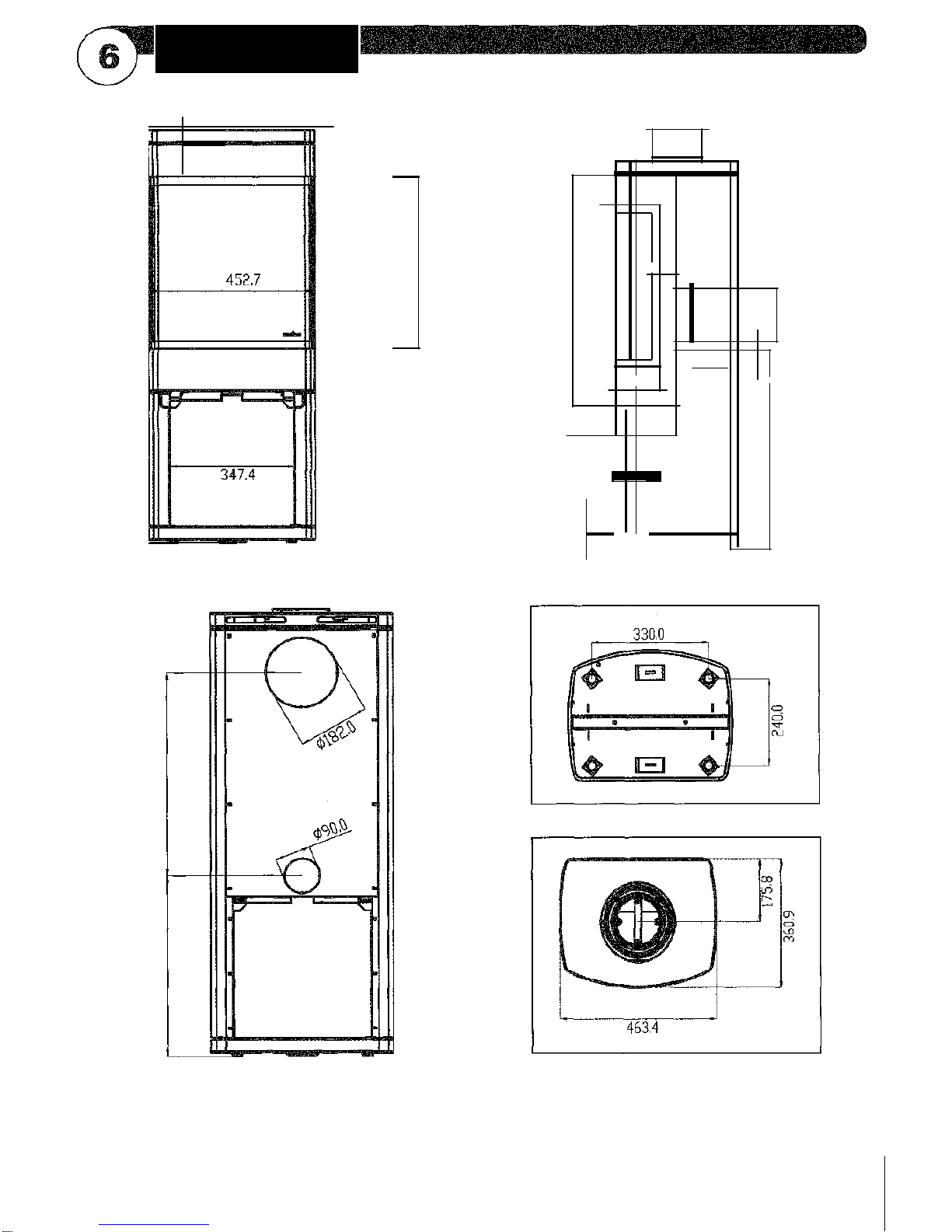
Fig. 6.1: Front of Unit
Ca.
CO CO
"4-CO
'2,4
179.8
I 1r
Fig. 6.2: Side of Unit
Fig. 6.3: Back of Unit
Fig. 6.4: Bottom of Unit
Fig. 6.5: Top of Unit
TECHNICAL DATA
Dimension Sketch Radius 300
0144,0
,1
4
43.4
Cu
to
7076-260 • January 12, 2015
A. Positioning Your Wood Burning Stove
The wood burning stove must be set up so the stove, flue
connection, flue pipe, and chimney system can be cleaned
and serviced. Consideration should also be made when
locating the appliance in the home due to the supply of
combustion air requirements. Depending on the chosen
installation method, supplied combustion air may be taken
from the outside using the adapters provided, or through
the back of the unit by removing the cover plate on the inlet
hole. (To remove the cover or install the outside air
adapter, remove the back panel. The cover plate is located
near the bottom and retained with four screws.)
Out of the box, the appliance without the additional weight
of the venting system or fuel load weighs nearly 100
kilograms. Make considerations for the weight of the
system when locating the unit in the desired location. If the
load bearing characteristics of the structure are difficult to
determine or there is concern that the structure will not
adequately support the system, a distribution plate should
be used. Contact your Radius Wood Stove dealer with
questions.
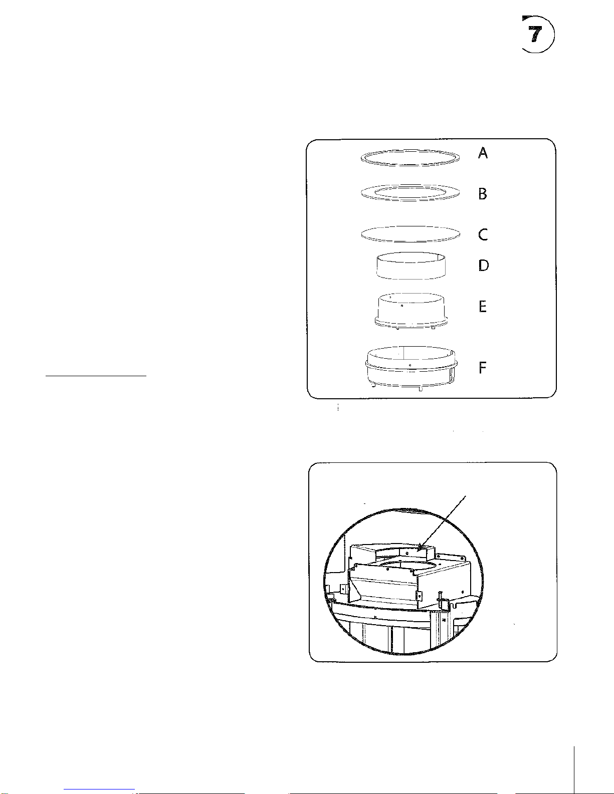
B. Vertical Venting & Combustion Air
When venting the appliance vertically, follow the venting
manufacturer's instructions and requirements. Slip the
cover ring down the flue and set on top of the appliance.
Vertical Venting Options (Fig. 7.1)
Standard 150mm Venting: E, B, F
Coaxial venting: F, E, D, A
(Use the items indicated for your installation. Use the bolts
provided to attach the components in the order shown.)
When installing F:
- If installing outside combustion air, turn F to cover the
opening at the top of the combustion air plenum.
- If using room combustion air or coaxial venting, turn F
to leave the opening at the top of the combustion air
plenum open.
(The outside air connection is located on the lower back
of the stove. The 75mm adapter is included in the
component pack.)
C. Horizontal Venting
When venting the unit horizontally, remove the back panel
of the unit. Next, remove the cast flue attachment ring in
the top of the appliance by removing the four bolts used to
secure it in shipping. Remove the rear cover plate that can
be seen in the back of the unit once the back panel is
removed. Install the rear cover plate over the vertical outlet
hole in the top of the unit using the four bolts that were
used to secure the cover plate when installed on the rear of
the unit. Install the cast flue attachment ring on the rear of
appliance using four bolts. Knock out the panel on the back
panel so the flue attachment ring can slip through it. Attach
the back panel back onto the appliance using
the same fasteners. Install the venting per the venting
manufactures specifications. Place the top cover plate
(item "C" in Fig. 7.1) from the component pack over the
hole in the top of the appliance for a finished look.
7076-260 • January 12, 2015
Fig.7.2
Opening at the top of the
combustion air plenum
Fig.7.1

This unit is suitable for installation in a shared flue.
Leveling the it
Four leveling bolts have come installed on the unit.
Following installation, adjustments can be made to the
heights of the four bolts from the top of the base pan. Use
a hex head bit to adjust the height of each of the four legs.
When in its final state, the unit should be secure and not
rock.
Position near to non-flammatla walls
When positioning near a non-flammable wall, we recom-
mend you keep a minimum distance of 50 mm between
the rear of the product and the wall for cleaning purposes.
Distance to furniture: 1000 mm
But please check to avoid furniture or other furnishings
being dried out due to being too close to the stove.
Distance to flammable walls
See. fig. 8.1.
UNIT
DIMENSIONS
HEARTH SIZE IN
FRONT
X (mm)
Y (mm)
Z (mm)
Radius 100
450
200
150
300mm
Radius 300
450
200
150
300mm
Fig. 8.1
7nimum Floor Protection Require-
ments
Component Pack
The component pack contains the following:
Manual
Gloves
Outside air connecting plate
Top adapter ring
Top flue cover plate
•Outside air screen
Removal of Radius from pallet
1. Remove the two 11 mm bolts holding the brackets in
the front and rear of the base on the unit, this requires
holding the bolt on the bottom side of the pallet as
shown in picture below on right
2. Tilt unit back unit the front bracket is able to tilt
forward and be removed from bottom of unit, repeat
tilting forward and removing rear bracket. (the brackets
need to swing down and slightly back in order to be
pulled from unit)
3. Unit can now be moved off pallet.
Fig. 8.3
INSTALLATION & ASSEMBLY
Fig. 8.2
Fig. 8.4
7076-260 • January 12, 2015

General Use
The Radius Series Wood Stoves are designed and tested
for intermittent use. This means that it is not designed for or
recommended to bum continuously for 24 hours.
This is a wood burning stove, the front, sides, and top will get
hot. Please use caution when you are near the fire especially
when it is burning.
Disposal of ashes and coals should always bein a non-com-
bustible container. Never put coals or embers into a flammable
container, even when they do not appear to be hot. Coals can
hold heat forextended periods of time and may cause damage if
improperly disposed of.
Prior to the start of the burn season or following extended periods
of non-use, you should inspect the firebox, flue connections, and
chimney system for debris and obstructions. Clean as necessary.
Contact your chimney sweep if needed.
Modification to your Radius appliance is prohibited, will void the
warranty, and may cause unsafe conditions during use. Certain
accessories are approved and available from your local Radius
Series Wood Stove Dealer.
Use only approved replacement parts available from your
Radius Series Wood Stove Dealer.
Lighting Instructions
Use paper or lighting briquettes and small pieces of wood to light
fire. Place the paper first in the bottom of the fire box and stack the
lighting briquettes orsmall pieces of wood on top of the paper. Do
not fill the firebox higher than the holes in the rear of the fire box.
(See Figures on next page).
Push in both air controls to open. Light the paper andleave the
door open slightly. As the small pieces of wood are burning add
slightly larger fuel on top of burning fuel and close the door. After
15-30 minutes or when good fireis established, close the lower
air control (it is located on the left side)by pulling it out
completely. When loading more wood during use, this control
may need to be pushed in to add more air under thefire.
Your First Fire
Duringthefirst firing ofthe Radiusitis tobe expected tosmoke and
give offunpleasantfumes.Thisiscausedbythepaint curingonthe
coatedsurfaces.Makesure the roomis wellventilatedto reducethe
inhalationofthesefumes.Afterthisfirstfirethe smokingand unpleas-
antsmell shouldgreatlydiminish.
As thepaint cures, therope seal onthedoormaysticktotheface
makingit difficultto open the front door. Toaidinthecuring process,
open thefrontdoorevery5 —10minutes forthefirstone totwo
hours.Thiswillkeepthesealfromforming abondtothefaceas the
coatingcurescompletely.
For the duration of this fire keep both air controls in the
completelyopenposition to ensure hotbumtocure stove.
Fuels
The Radius Series wood stoves are designed to burn a
wide range of firewood species. In general hardwoods are
better for heating since they burn more evenly. When
operating the unit with different types of fuels, refer to
operating the wood stove section for more information.
Consult the internet for specific heating values of different
species of firewood.
The optimal size of firewood for the Radius Series wood
stove is 25 cm long and 6 cm —12 cm in diameter when
split. Some varieties of fuels may perform better when split
smaller. When establishing a fire, it is helpful to have a
variety of different diameters in order to heat the flue up
quickly and establish the draft.
Fuels should be stored in locations protected from rain and
excessive moisture. Well seasoned firewood may take 1 -2
years to dry out. Well ventilated areas protected from
environmental elements aid in preparing the fuel faster. If the
fuel is stored outside, it is recommended that it is stored inside
a few days before use to allow the fuel to warm up to room
temperature.
Firewood and combustible items should NEVER be stored
below the firebox. Make sure the proper clearance to
flammable materials is maintained for all fuel storage. The
firewood used should have a moisture level less than
20%. The Radius Series wood stove will yield its best
performance if the moisture content is between 15% and
18%. Moisture levels above 20% can have adverse
environmental effects because of the inefficient burn.
Moisture levels below 15% will burn faster resulting in
shorter burn times. To determine whether your fuel is too
wet, knock it on a hard surface. If it is too wet, the sound
produced will be dull.
Burning wet wood reduces the amount of heat output into
your home because it is turning the water into steam and
venting it out your chimney rather than producing gases
that are burned up in the secondary system. It also
increases the amount of soot on the glass and in the
chimney system. It is inefficient and produces pollution.
Improper use including the use of illegal fuels may cause
pollution and can damage the appliance. Improper use will
void the manufactures warranty. Never burn treated or
painted wood, chipboard, glued or laminated materials,
wood from salt water, plastics, trash, or chemically treated
paper.
7076-260 • January 12, 2015

INSTRUCTION FOR USE
Fig.10: Proper Fill and Startup Configuration
Fig. 10.1: Add paper to back of firepot making sure to not
block lower air inlet with paper.
Fig. 10.2: Add small pieces of wood on top of paper
allowing for air flow between pieces.
Fig. 10.3: Add larger log on top of pile making sure it
does not go above the upper intake holes.
7076-260 • January 12, 2015

Primary Air (Lower it Control)
(Figure 11.1)
The primary air is controlled by the lever on the left side of
the appliance. When the control arm is pulled out, less air is
allowed into the firebox below the fire. When the control arm
is pushed in, maximum air is allowed in under the fire. This
lever is to be used during start up and refueling. If this air
control remains open (pushed in) then you will have
reduced burn times or a potential to overheat the appliance.
Upper it Control (Figure 11.1)
The upper air control is controlled by the lever on the right
side of the appliance. When the control arm is pulled out,
less air is allowed into the firebox through this system.
When the control arm is pushed in, maximum air is allowed
through the system. The function of this air control is to
regulate the burn rate of the fire and provide air for the air
wash system to keep the glass clean.
When the upper air control is closed and air is reduced to
the air wash system, the glass will soot up. This is normal
and to be expected. To help clean the glass off, add
additional fuel to the fire, pull out the upper air control and
pull out the lower air control lever for 15-30 minutes to
establish a hot fire. A hot fire with the upper air control
open will aid in cleaning the glass.
Fig. 11.1: Air Controls
Secondary Air (holes in rear of firebox)
This unit is equipped with a secondary combustion system
that cannot be regulated. The purpose of this secondary
system is to provide air that will mix with the combustion
gasses and burn them. This reduces the amount of debris
and gasses being let out into the environment ensuring a
clean burn.
Airwash System
An air wash system is built into the appliance and is
controlled by the air control lever on the right side of the
appliance. Even with this air wash system, the glass panes
will get dirty and have build up. This is normal and can be
cleaned using a simple glass cleaner. Alternate glass
cleaning products specifically designed for cleaning glass
panes on wood burning stoves may be available from your
dealer. Contact them directly for product availability.
Front Door Handle Operation
(Figure 11.2)
To open the front door, pull the lever located on the right
side of the unit upwards (be sure to wear the glove
provided if the unit is hot). Carefully swing the door open
from right to left. To close the door swing it shut from left
to right and close by pushing the handle down. When
securing the front door closed, make sure the roller on the
handle is beyond the ramp catch located on the side of the
unit.
1- Pull side of handle away 2- Then swing door open to the
from unit. left.
Fig. 11.2: Door Handle Operation
Lower (primary) Air Upper (secondary)
Intake Control Air Intake Control
7076-260 January 12, 2015

Front Door Se&
The front door has a non-combustible rope which creates a
tight seal for the firebox. The first time you open the front
door and close it, the gasket may be stiff and the door
difficult to close. Following the first fire, the gasketing will
relax which will allow the door to be closed easily for
normal use which provides a tight seal. This seal is critical
for proper air regulation in the firebox for safe and efficient
burn. Though this material is a high quality material
specifically designed for wood burning appliances, it is
subject to normal wear and tear and should be replaced if
burn times are reduced or there is concern of leakage. The
seal is subject to damage from excessive cleaning or by
debris being closed in the door.
If there is a concern of leakage, use a thin piece of paper,
place against the gasket in the area of concern, close the
door and latch shut, then gently tug on the paper. If the
paper comes right out without any resistance, the seal
should be replaced.
Chimney System
A chimney or flue system is required to run your wood
stove safely and efficiently. When a fire is started in the fire
box hot gases are released and exit the firebox into the
chimney system. These hot gases heat up the chimney
system and create a vacuum in the firebox or commonly
referred to as drafting. As a result, more air is pulled into
the firebox through the air openings. When more air is
pulled into the fire, the fire burns hotter and is a cleaner
burn. This also means that the burn time is shorter but
more heat is generated to heat the living space and the
glass stays cleaner. When the air controls are adjusted
and reduced, the fire will slow down. This lowers the draft
and as a result, the burn times are longer.
When lighting the appliance, it is important to get a hot fire
as quick as possible to establish the draft in the system for
an efficient and clean burn. There are many different types
of chimney systems, check with your local authority for
more details and follow all regulations in your area.
Drafting
Weather and chimney location can affect the draft of your
stove resulting in different performance settings. For windy
conditions, the draft may be higher which will result in
changing the air control settings for the same
performance. In areas where high wind is common, a
damper may need to be installed in the flue pipe to best
control the appliance. Performance can also be influenced
by changes in humidity including fog. Adjust the air
controls as needed to achieve the desired heat output of
your Radius wood burning stove.
Figure 12.1
Windward
Recommended:
Outside Air Intake
on windward side
NOT recommended:
Outside Air Intake
on leeward side
Multi-level Roofs
RecommendedLocation:
Recommended Location: • Above peak
Above peak • Inside heated space
Location NOT recommended:
Not the highest point of the roof
Windloadingpossible
Marginal Location:
Below peak
Recommended:
Insulated exterior chase
in cooler climates
Marginal Location:
Windloadingpossible
Location NOTrecommended:
Too close to tree
Below adjacent structure
Lower roof line
Avoidoutside wall
7076-260 • January 12, 2015

Ash Drawer
(Figure 13.1)
Before attempting any maintenance on the unit ensure that
the unit is cold and has no embers in the firebox. To access
the ash drawer open the front door. The drawer is located
under the firebox. Before removing pan empty ash from
firebox into the pan.
To do this open the grate at the bottom of the firepot by
pushing the primary air control lever on the left side all the
way in until all holes are open. Then gently sweep ash
through the grate into the ash drawer below. Then, pull the
primary lever forward to close the grate so that only the two
small holes in the back of the unit are open.
Then remove the ash pan drawer and empty into
noncombustible container. Never attempt to open ash pan
when stove is lit.
Figure 13.1: Ash Drawer Maintenance
1- Push in primary air control to
turn grate clockwise to open all
grate holes. After all holes are
open, push ash through grate to
drawer below.
Baffle Material
There are two baffle plates in the top of the unit. The
purpose of these plates is to restrict and direct the
combustion gases to allow for complete combustion of the
gasses prior to exiting the firebox and entering the flue.
The lower baffle plate is supported on each side by the
side refractory, it is notched on either side to allow proper
placement.
The upper baffle panel is supported by two brackets, one
on each side of the top of the firebox. During annual
chimney maintenance, these two baffle panels must be
removed prior to sweeping. Not doing so will result in
broken panels. Similar to the refractory panels lining the
inside of the firebox, the baffle panels are subject to wear
and tear and are subject to warranty limitations.
Fc-:.Proper Burn
Remove ash from firebox and ash pan regularly to
ensure proper air supply
Use only 1-3 pieces of wood quartered and placed to
optimize air flow (see Figure 10.2)
® Adjust the upper air control to ensure that enough air
is being supplied to the firebox, there should always
be a visible flame with minimal smoke
® Fuel should never be stacked above the upper air
inlets (see Figure 10.3)
Coated Surfaces
To clean the stove dust with a lint-free cloth or cleaning
device. If the topcoat is damaged it is possible to purchase
a repair spray from your local dealer. It is possible that this
spray may be slightly different from the original coat. For
best results, use repair spray in wide area in order to create
a subtle transition from one color to the next. For safety
purposes apply spray when stove is cold, the difference in
color may be very noticeable when first applied. However,
after firing again it should match very close to original color.
2- Remove drawer by pulling out
and empty into qualified
container.
Refractory
The firebox is lined with molded refractory firebrick. The
refractory protects the outside of the appliance and retains
the heat necessary for a clean efficient burn. The material is
a porous ceramic material that can break from abuse.
Occasionally, surface cracks may propagate from normal use
through the heating and cooling cycle. Surface cracks are
normal and should only be a concern when the crack causes
the refractory to not remain in place on its own.
Cleaning the Glass
This stove is designed to minimize soot build-up. To attain
this the stove must be burned properly, see section For
Proper Burn.
However even when burned properly a slight buildup of soot
can occur. To clean you can use dry cloth and regular glass
cleaner or specialized stove glass cleaning products.
7076-260 • January 12, 2015
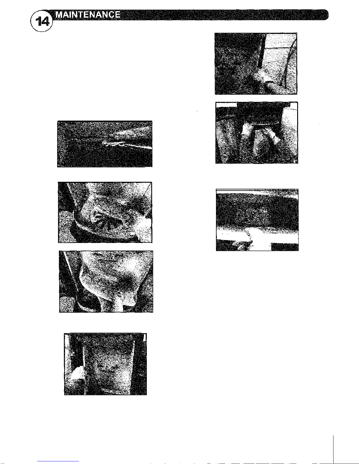
3. Lift out the Firepot Plate and then the Firepot.
4. Lift Baffle (Top piece) slightly and remove left and
right sides then the Lower Back Refractory.
5.
Remove the Baffle by lowering the front and pulling out.
Be careful to not let the Upper Rear Refractory fall.
6. Remove the Upper Rear Refractory. If you are convert-
ing to rear vent, discard the Upper Rear Refractory
Installation is the reverse of the removal.
Removal of Radius refractory for
service or rear venting conversion.
Refractory that has been burned is fragile and must be
handled carefully to prevent breakage.
Remove Ash Drawer and set aside.
1. Using a pair of pliers; remove pin that secures
the Firepot
2. Plate to the Primary control damper. This can be
accessed in the ash drawer cavity below the firebox.
7076-260 • January 12,2015
Smoke escaping
Damp wood
Chimney not drawing properly
Chimney is not properly dimensioned for the stove
Check if the smoke gas pipe/chimney are blocked
Is the chimney the right height for its surroundings?
At rear outlet, check that the flue pipe does not obstruct
the chimney draught
Vacuum in room
The door is opened before the embers have
burned down sufficiently
Wood burning too quickly
The air valves are set incorrectly
The baffle plates are incorrectly mounted or missing
Inferior firewood (waste wood, pallets etc.)
Chimney too large
Soot build-up on glass
Incorrect secondary airflow setting
Excessive primary air
Damp wood
Wood pieces too large on lighting
Inferior firewood (waste wood, pallets etc.)
Chimney not drawing sufficiently
Vacuum in room
Excessive soot build-up in chimney
Poor burning (more air required)
Damp wood
The surface of the stove is turning grey
Overheating (see instructions for heating)
Poor heating performance of stove
Damp wood
Not enough wood
Inferior wood quality with low fuel value
Baffle plates are not fitted correctly Odor coming from
stove
The lacquer on the stove hardens when you use the
stove for the first time; this can cause an odor. Open a
window or a door for ventilation, and make sure the stove
is heated up sufficiently to avoid odors later.
When heating up and cooling down, the stove may
make some clicking noises. These are due to the huge
temperature differences to which the material is
exposed and do not indicate any product defects.
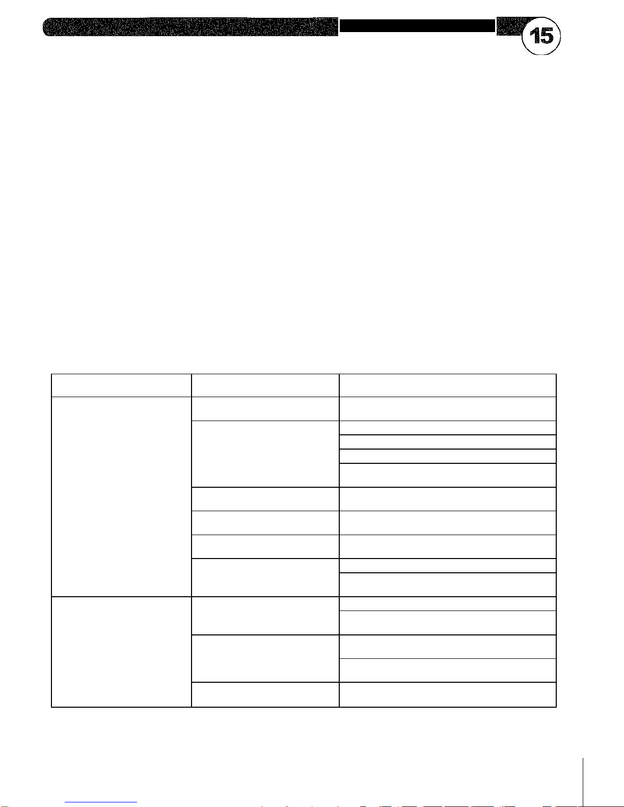
Start Fire Problems
Possible Cause
Solution
Can't get fire started
Excessive smoke or
spillage Burns too slowly
Smolders, sizzles
Not enough kindling/paper or no
kindling/paper
Use dry kindling, more paper. Arrange kindling &
wood for air movement.
Not enough air for fire to ignite
Check for restricted cap/shroud
Open outside air kit (if installed).
Check for flue blockage.
Check for adequate vent height (refer to chimney
assembly section).
Wood condition is too wet, too
large
Use dry, seasoned wood (refer to wood fuel sec-
tion).
Bed of coals not established
before adding wood
Start with paper & kindling to establish bed of
coals (refer to starting fire section).
Flue blockage such as birds'
nests or leaves in termination cap
Have chimney inspected for creosote and cleaned
by a certified chimney sweep.
Down draft or negative pressure
Competition with exhaust devices
Do not use exhaust fans during start-up.
Open window below the appliance towards the
wind.
Fire burns too fast
Extremely dry or soft wood
Mix in hardwood.
Mix in less seasoned wood after fire is established
(refer to wood fuel section).
Overdrafting
Check for correct vent height; too much vertical
height creates overdrafting.
Check location of vent termination (refer to chim-
ney requirements section).
Ash pan may not be closed corn-
pletely
Close ash pan.
7076-260 • January 12, 2015
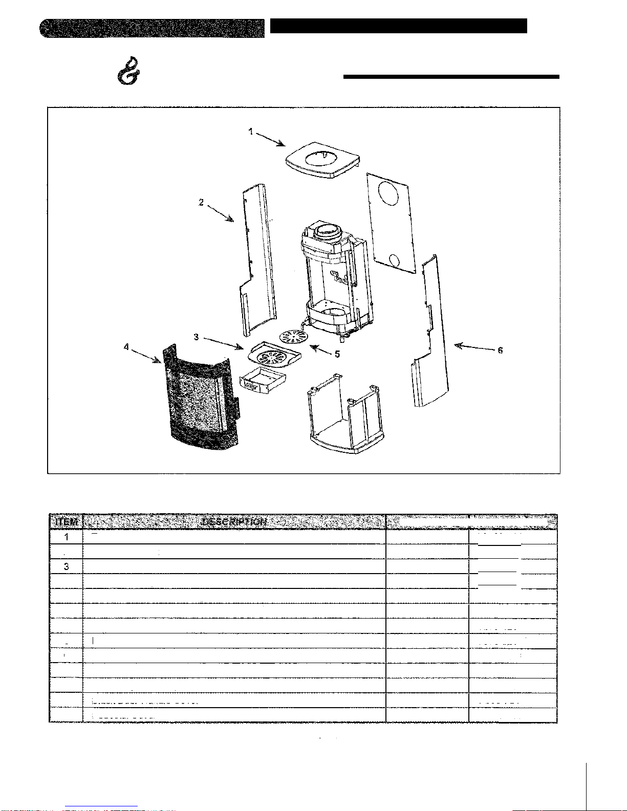
TROUBLESHOOTING

RADIUS-100
Beginning Manufacturing Date: Sept 2013
Ending Manufacturing Date: Active
IMPORTANT: THIS IS DATED INFORMATION. Parts must be ordered from a dealer or distributor. Hearth and Home Technologies does
not sell directly to consumers. Provide modelnumber and serial numberwhen requesting service parts from your dealer ordistributor.
ITEM
DESCRIPTION
COMMENTS
PART NUMBER
1
Top
MG08-181
2
Side Panel, Left
7G08-551
3
Cast Firepot
7076-332
4
Door Assembly
7076-008
Door Handle Assembly
7076-018
Door Rope
IG08-041
Glass
IG08-011
5
Firepot Plate
7076-023
6
Side Panel, Right
MG08-551
Refractory Side Door
IG08-091
Refractory Assembly
MG08-511
Black Door Handle Cover
7G08-751
Pedestal Cover
MG08-501
7076-260 • January 12, 2015
Service Parts & Accessories List
Service Parts
Wood Stove
No one builds a better fire
IMPORTANT: THIS IS DATED INFORMATION, Parts must be ordered from a dealer or distributor. Hearth and Home Technologies does
not sell directly to consumers. Provide model number and serial number when requesting service parts from your dealer or distributor.
Service Parts & Accessories List
Service Parts
C3 11IMMIN--
Wood Stove
RArlUS-300
Beginning Manufacturing Date: Sept 2013
Ending Manufacturing Date: Active
HEAT
No one builds a better fire
Top
2
Side Panel, Left
Cast Firepot
4
DoorAssembly
Glass
7075-125
FirepotPlate
5
7076-023
6
MGOS-551
Side Panel, Right
Refractory b y
MG08-511
Black Door Handle Cover
7G08-751
C O M M E N T S A R T N U M B E R
Pedestal Cover
7076-260 - January 12, 2015
MG08-501
MG08-181
7G08-551
7076-332
7076-007
7076-018
1G08-041
Door Handle Assembly
Door Rope

H E A R T 1 1 6 - H O M E
technologies
AUSTRALIAN WARRANTY INFORMATION
Hearth & Home Technologies Inc (HHT)
1445 N. Highway I Colville, WA 99114 I (509-684-3745)
HHT extends the following manufacturer's warranty for HHT gas, wood, pellet, coal and electric hearth appliances that are purchased
from an HHT authorized dealer.
HHT warrants to the original owner of the HHT appliance at the site of installation, and to any transferee taking ownership of the
appliance at the site of installation within two years following the date of original purchase, that the HHT appliance will be free from
defects in materials and workmanship at the time of manufacture.
After installation, if covered components manufactured by HHT are found to be defective in materials or workmanship during the
applicable warranty period, HHT will, at its option, repair or replace the covered components. HHT, at its own discretion, may fully
discharge all of its obligations under this manufacturer's warranty by replacing the product itself or refunding the verified purchase price
of the product itself. The maximum amount recoverable under this warranty is limited to the purchase price of the product. This warranty
is subject to conditions, exclusions and limitations as described below.
Warranty coverage begins on the date of original purchase. In the case of new home construction, coverage under this manufacturer's
warranty begins on the date of first occupancy of the dwelling or six months after the sale of the product by an independent, authorized
HHT dealer/ distributor, whichever occurs earlier. The warranty period for this manufacturer's warranty shall commence no later than 24
months following the date of product shipment from HHT, regardless of the installation or occupancy date. The manufacturer's warranty
period for parts and labor for covered components is produced in the following table.
The term "Limited Lifetime" in the table below is defined as: 20 years from the beginning date of warranty coverage for gas appliances,
and 10 years from the beginning date of warranty coverage for wood, pellet and coal appliances. These time periods reflect the minimum
expected useful lives of the designated components under normal operating conditions.
Gas Wood Pellet
Labor
W o od Co al E lec tr ic V e nt in g
X
X
2years
Castings and baffles
5 years r 1 year
Manifold tubes,
HHT chimney
and HI-, ea
7 years 3 years
All replacement parts
urners, ogs an
Fireboxandheat
3years
90Days
7076-260 January 12, 2015
=15':Wiiirlin:111M1-17giTirAtif=iFigliMEMMMIATIMatitimilitivilff-I Is
Parts
All parts and material
except as covered by
Conditions, Exclusions,
and Limitations listed
X
X
X
X
X
1Year
Igniters, electronic
onnoopents, alass
actory-installed blowers
Molded refractory panels
3 ears X Fire ots and Burn ots
Components Covered

OTHER RIGHTS
The HHT manufacturer's warranty is in addition to other rights and remedies that you may have under Australian
law.
Our goods come with guarantees that cannot be excluded under the Australian Consumer Law. You are entitled to a
replacement or refund for a major failure and for compensation for any other reasonably foreseeable loss or damage.
You are also entitled to have the goods repaired or replaced if the goods fail to be of acceptable quality and the failure
does not amount to a major failure.
WARRANTY CONDITIONS AND EXCLUSIONS:
The HHT manufacturer's warranty only covers HHT appliances that are purchased through an HHT authorized dealer or distributor. A list of
HHT authorized dealers is available on the HHT branded websites.
This warranty is only valid while the HHT appliance remains at the site of original installation.
WARRANTY EXCLUSIONS:
This HHT manufacturer's warranty does not cover the following:
Changes in surface finishes as a result of normal use. As a heating appliance, some changes in color of interior and exterior surface
finishes may occur. This is not a flaw and is not covered under warranty.
Damage to printed, plated, or enamelled surfaces caused by fingerprints, accidents, misuse, scratches, melted items, or other external
sources and residues left on the plated surfaces from the use of abrasive cleaners or polishes.
Repair or replacement of parts that are subject to normal wear and tear during the warranty period. These parts include: paint, wood, pellet
and coal gaskets, firebricks, grates, flame guides, light bulbs, batteries and the discoloration of glass.
Minor expansion, contraction, or movement of certain parts causing noise. These conditions are normal and complaints related to this noise
are not covered by this warranty.
Damages resulting from: (1) failure to install, operate, or maintain the appliance in accordance with the installation instructions, operating
instructions, and listing agent identification label furnished with the appliance; (2) failure to install the appliance in
accordance with local building codes; (3) shipping or improper handling; (4) improper operation, abuse, misuse, continued operation
with damaged, corroded or failed components, accident, or improperly/incorrectly performed repairs; (5) environmental conditions,
inadequate ventilation, negative pressure, or drafting caused by tightly sealed constructions, insufficient make-up air supply, or
handling devices such as exhaust fans or forced air furnaces or other such causes; (6) use of fuels other than those specified in the
operating instructions; (7) installation or use of components not supplied with the appliance or any other components not expressly
authorized and approved by HHT (8) modification of the appliance not expressly authorized and approved by HHT in writing; and/or (9)
interruptions or fluctuations of electrical power supply to the appliance.
Non HHT venting components, hearth components or other accessories used in conjunction with the appliance.
Any part of a pre-existing fireplace system in which an insert or a decorative gas appliance is installed.
Removal, installation, reinstallation, set up or any other costs associated with a claim including travel and shipping charges for parts
HHT's obligation under this warranty does not extend to the appliance's capability to heat the desired space. Information is provided to
assist the consumer and the dealer in selecting the proper appliance for the application. Consideration must be given to appliance location
and configuration, environmental conditions, insulation and air tightness of the structure.
This warranty is void if:
The appliance has been over-fired or operated in atmospheres contaminated by chlorine, fluorine, or other damaging chemicals. Over-firing
can be identified by, but not limited to, warped plates or tubes, rust coloured cast iron, bubbling, cracking and discoloration of steel or
enamel finishes.
The appliance is subjected to prolonged periods of dampness or condensation.
There is any damage to the appliance or other components due to water or weather damage which is the result of, but not limited to, improper
chimney or venting installation.
HOW TO CLAIM
To make a claim against this warranty, contact your local distributor during regular business hours. See addresses below
for a dealer nearest you. (Vic) Pty Ltd ACN 005 872 159 (Jetmaster).
Additional service fees may apply if you are seeking warranty service from a dealer other than the dealer from whom you
originally purchased the product.
Check with Jetmaster in advance for any costs to you when arranging a warranty call. Travel and shipping charges for
parts are not covered by this manufacturers' warranty.
HHT and Jetmaster will assess your claim. HHT or Jetmaster may need to inspect the product as part of the assessment of your claim.
If the product requires inspection, HHT or Jetmaster will discuss with you the best way for this to occur.
To make a claim under this manufacturer's warranty, you must be able to prove when you purchased the product. The easiest way to
do this is through your original proof of purchase, for example your invoice or receipt. However, if you do not have your original proof of
purchase HHT or Jetmaster may accept other evidence of the date of purchase.
Local Distributors:
Melbourne
Jetmaster
44 Swan Street
Richmond 3121
(03) 9429-5573
Perth
Fireplace Corner
277 Lord Street
East Perth 6000
(08) 9228-2600
Sydney
Jetmaster
10 Martin Avenue
Arncliff 2205
(02) 9597-7222
7076-260 • January 12, 2015

We recommend that you record the following pertinent information
for your heating appliance.
Date purchased/installed: ________________________________________
Serial Number: __________________________________________________ Location on appliance: ___________________
Dealership purchased from: ________________________________________ Dealer phone: __________________________
Notes: ________________________________________________________________________________________________
H F A I : T H & H O _
technologies
CONTACT INFORMATION:
Hearth & Home Technologies
1445 North Highway
Colville, WA 99114
Division of HNI INDUSTRIES
This product may be covered by one or more of the following patents: (United States) 5341794, 5263471, 6688302, 7216645,
7047962 or other U.S. and foreign patents pending.
H E A R T H & H O M E
technologies
7076-260 • January 12, 2015
Table of contents
Popular Wood Stove manuals by other brands


Charnwood
Charnwood I S L A N D Operating & installation instructions

Harvia
Harvia Legend 150 Instructions for installation and use

pleasant hearth
pleasant hearth PH35PS-B owner's manual

Jøtul
Jøtul F 400 Castine Installation and operation instructions

Regency
Regency Classic F2450M Owners & installation manual

Lotus
Lotus 2000 Series Mounting and user instructions

Vogelzang International
Vogelzang International PONDEROSA TR007 owner's manual

RAIS
RAIS RONDO user manual

Palazzetti
Palazzetti Cindy Instructions for use and maintenance

Beltane Stoves
Beltane Stoves HOLFORD Installation and operating instructions

Morso
Morso 7370 Installation

ACR STOVES
ACR STOVES Wychwood WYC1WB Technical manual