Belfort 134 04 11 User manual
Description of the appliance
Installation instructions
Operating instructions
Spare parts
Warranty certificate
Belfort
Wood or coal stove
Model : 134 04 11
Output : 4,5 kW
NF EN 13240
Document n° 1174-3 ~ 15/10/2004
STAUB FONDERIE
Head Office Address
2, rue Saint Gilles
68230 TURCKHEIM
RC Colmar
SIREN 439 330 325
Address - Administration and
manufacturing
BP 73
59660 MERVILLE (FRANCE)
Telephone : 00 333 28 43 43 43
Fax : 00 333 28 43 43 99
Subject to modifications.
ÈEEN NL PL IT
Technical manual
to be saved
by the user
for future reference
FR EN NL PL IT

2Technical manual “1174”
“BELFORT” - ref. 134 04 11
CONTENTS
Product information .....................................p.3
Package .................p.3
Optional equipment ...........p.3
General characteristics . . . ......p.3
Description . . . . . . . . . . . . . . . . p. 3
Principle of operation . . . . . . . . . . p. 3
Installation instructions...................................p.4
Warning to the user ...........p.4
Location of the unit ...........p.4
Flue . . . .................p.4
Assembly of flue spigot and blanking plates
......................p.5
Chimney connector . . . . . . . . . . . p. 5
Maintenance of the stove body . . . . . p. 6
Door closing pressure . . . . . . . . . . p. 6
Pre-utilisation check . . . . . . . . . . . p. 7
Chimney maintenance and sweeping . p. 7
Instructions for user.....................................p.8
Fuel . . . .................p.8
Instructions for use with wood .....p.9
Instructions for use with solid fuel . . . p. 9
Cleaning .................p.9
Maintenance of the stove . . . . . . . p. 10
Recommendations . . . . . . . . . . . p. 10
Firebricks . . . . . . . . . . . . . . . . p. 10
Trouble Shooting . . . . . . . . . . . . p. 10
Spare parts .........................................p.11
FRANCO BELGE congratulates you on your choice.
FRANCO BELGE, which has been granted the ISO 9001 certification, guarantees the quality of its
appliances and is committed to meet its customers’ needs.
FRANCO BELGE, which can boast a 75-year experience in the industry of heating devices, uses
state-of-the-art technologies
to design and manufacture its whole range of products.
This document contains instructions on how to install your appliance and make full use of its
functions, both for your comfort and safety.
This appliance is meant to burn wood or solid fuel safely.
WARNING
An incorrectly installed oil-fired stove can cause serious accidents.
This appliance should only be installed by competent personnel.
1. Product information
1.1. Package
•1 package : Stove complete.
1.2. Optional equipment
•Optional for Great Britain : Water jacket.
•Set of 4 hight legs.
1.3. General characteristics
Reference ................ 1340411
Maximum output ...........kW 4,5
Chimney draft required ........Pa 20
Grate dimensions :
- width ................mm 270
- depth ................mm 200
- usable height ............mm 240
Max. log size .............cm 25
Ash pan capacity ..........litres 3
Net weight ..............kg 77
Autonomy ................h 7,30
1.4. Description
Intermittent-burning heating appliance.
Wood burnt on grate
Wood burning stove
Close cast iron firebox
Removable appliance, to be installed near a wall.
•Detachable flue spigot for rear or top chimney
connection.
•Detachable top for easy handling and cleaning (rear
smoke exit only).
•Adjustable air controls for controlling the burning rate.
•Spin wheel for lighting.
•Large ash-pan.
•Grate shaker control.
1.5. Principle of operation
The “ Belfort ” is designed for operation with the door
closed.
Heat is mainly diffused by radiation, through the window
and body of the appliance.
Combustion occurs on the grate, with draught entry
through the top of the combustion chamber when using
wood and under the grate when using coal.
Technical manual “1174” 3
“BELFORT” - ref. 134 04 11 Product information
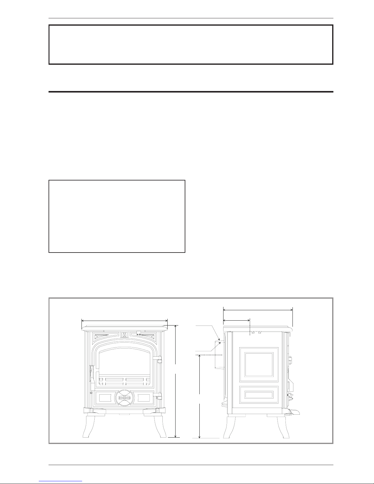
420
550
409
Ø 125
131
340
Ø 139
Figure 1 - Dimensions in mm
2. Installation instructions
2.1. Warning to the user
An incorrectly installed heating appliance can
cause serious accidents (chimney fires, burning of
plastic insulation materials, in partition walls, etc.).
The insulation of both the appliance and the exhaust
gas pipe has to be reinforced and done according to the
Standards and the Building Regulations for safety
reasons. The installation must be carried out according
to the Standards and the Building Regulations.
Failure to respect the mounting instructions leads to
engage the responsibility of the one doing the
installation.
The manufacturer’s responsibility shall be limited to the
supply of the appliance.
2.2. Location of the unit
Ventilation :
For satisfactory appliance operation with a natural
draught, check that sufficient air for combustion is
available in the room.
Position of the unit :
For new installations, select a central position within the
house, to provide a good heat distribution around the
building.
The heat distribution towards the other rooms will be
made through the communicating doors.
These rooms must be in negative pressure or must
include ventilation gratings.
Floor and walls :
Make sure they are not combustible or covered with
combustible material (as per the Building regulations).
Otherwise it must necessary to install a
non-combustible protection.
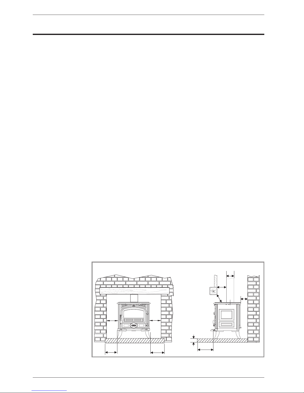
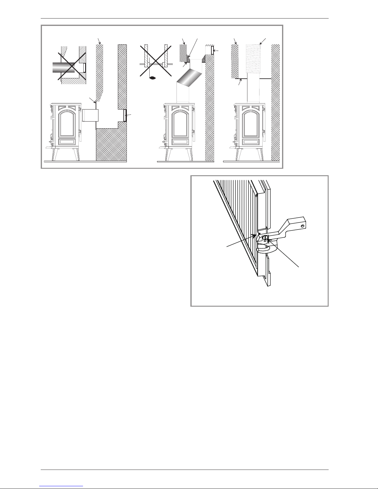
There must be a clearance of at least 150 mm at each
side of the appliance and at the back of the appliance
from a non-combustible wall.
This distance must be extended to a minimum
clearance of 350 mm from any combustible materials.
This measurement may be reduced to a minimum gap
of 50 mm when the
non-combustible wall is at
least 200 mm thick.
When using a single wall
flue pipe, there must be a
clearance (A) of at least
three times its diameter (B)
from any combustible
materials.
If the appliance has to be
located in an opening, this
distance must be extended
to a minimum clearance (A)
of 375 mm from the pipe or
the stove body to any
combustible materials.
Hearth
The appliance must stand
on a fireproof hearth.
The hearth must be made of
non-combustible material of
thickness 12 mm minimum (C). This may include the
thickness of a non-combustible floor.
The hearth must protrude at least 225 mm in front of the
stove and 150 mm each side.
If the hearth is constructed on timber, there must be a
clearance of at least 250 mm from the timber to the top
surface of the hearth.
2.3. Flue
The chimney must comply with Current Building
Regulations. If in doubt, consult your Dealer or local
Building Inspector.
Existing flue :
-The flue must be in good condition and must provide
sufficient draught.
-The flue must be suitable for the installation of solid
fuel burning appliances and comply with Current
Building Regulations.
-The flue must be clean. It should be swept to remove
soot and dislodge tar deposits.
-The flue must be well insulated. If the flue inner wall
surfaces are cold, a good thermal draw is impossible
causing condensation problems (tar formation etc) to
occur.
-The flue must not be shared with other appliances.
-The chimney must be at least 4.5 m (15 ft high).
-In case of a flat roof or when the roof gradient is lower
than 15°, the stack must be 1,2 m (4 feet) high at least.
-If the chimney has any down draught tendency, due to
its position in relation to nearby obstacles, then an
anti-down draught cowl must be installed on the
chimney or the chimney height must be increased.
-If the decompression in the chimney is excessive, a
draught stabiliser must be installed.
Chimney to be built / Flue non-existent :
-The flue must not be supported by the stove.
-Consult a chimney specialist for advice on suitable
flue systems for solid fuel appliances.
4Technical manual “1174”
“BELFORT” - ref. 134 04 11 Installation instructions
#
# # !
#
*
)
)
+
#
Figure 2 - Clearances
2.4. Assembly of flue spigot and blanking
plates
The stove is supplied with a connection flue spigot with
an inner diameter of 125 mm or an outer diameter of
139 mm.
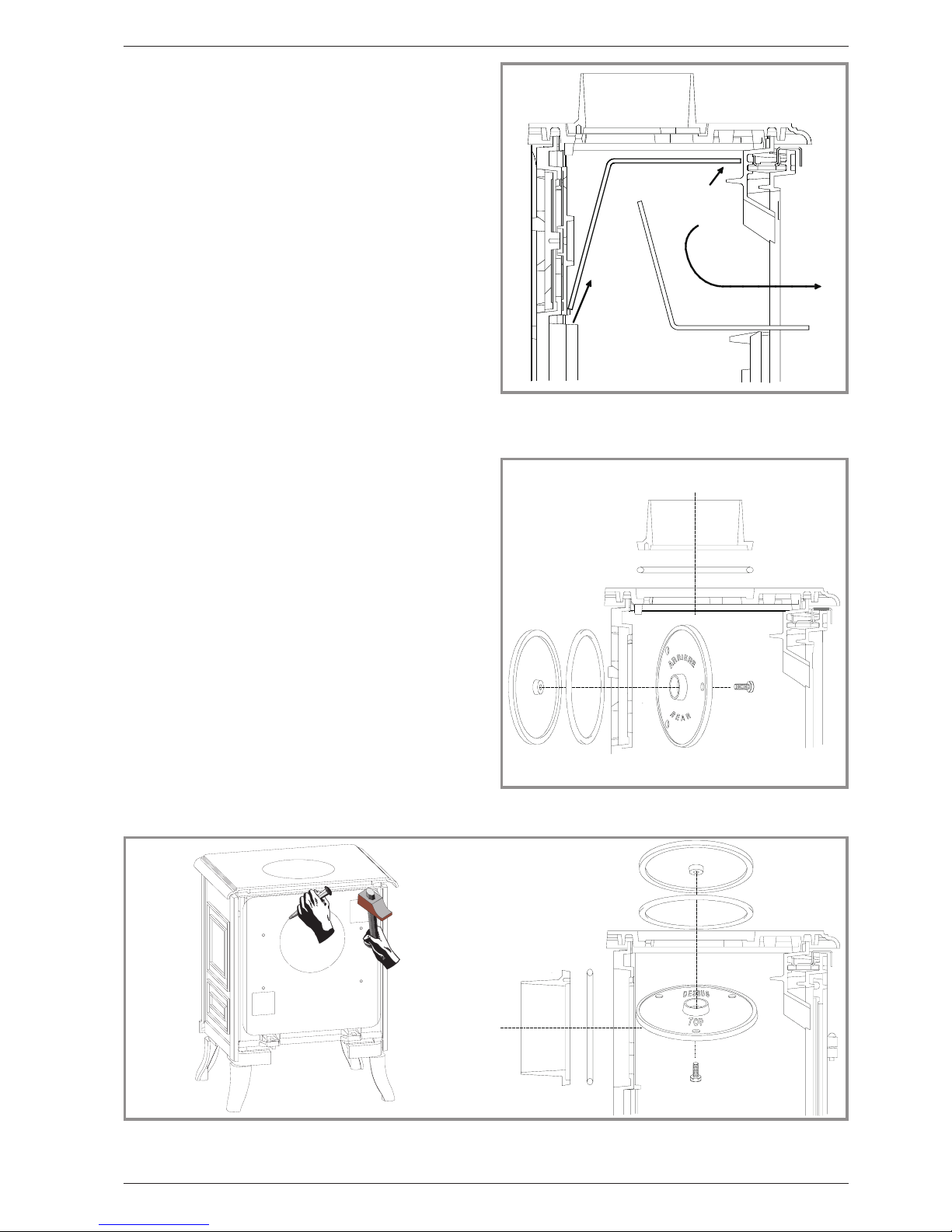
2.4.1. Smoke exit on the top
Figure 4
-Remove the internal baffle ( # 17, page 13).
-Fit the sealing rope in the groove and attach the flue
spigot (# 26, page 13) using the three bolts and
washers supplied.
-Check that the two blanking plates are fixed to the
back wall (# 25 & 35, page 13)
-Replace the internal baffle.
2.4.2. Smoke exit at rear
Figure 5
-Remove the internal baffle (# 17, page 13) and the rear
heat shield (# 16, page 13).
-Fix the sealing rope in the groove on the rear and fit
the flue spigot, ensuring there is a good seal.
-Fix the sealing rope in the groove on the top and fit the
two blanking plates, ensuring there is a good seal.
-Replace the internal baffle.
-Remove the cut-out in the rear heat shield and re-fit.
2.5. Chimney connector
-The appliance must be installed as close as possible
to the chimney.
-The connector pipe must be approved for installation
with combustion products (either 24 ga. Black painted
or blued steel or 316 grade 20 ga. Stainless steel or 1
mm vitreous enamelled steel).
-Pipe diameter must not be less than the appliance
spigot diameter. If there is no other solution, the
reduction can not be more than one diameter lower
than the flue spigot and be situated as distant as
possible from the flue connection of the appliance.
Technical manual “1174” 5
“BELFORT” - ref. 134 04 11 Installation instructions
1
2
3
Figure 3 - Removing the flue baffle
Figure 4 - Smoke exit on the top
Figure 5 - Smoke exit at rear
-The connection can be either vertical or horizontal. For
horizontal connections, avoid right angle bends.
-The join between the connection pipe and the
stovepipe, and the flue, must be leak tight.
-The connection pipe and any draught stabiliser must
have access for cleaning.
-The spigot should be connected to a minimum of 125
mm flue system and in that case the appliance is
capable of burning untreated wood and recommended
solid fuels.
2.6. Maintenance of the stove body
•The stove must be regularly cleaned.
•Remove all deposits from the combustion chamber
and clean the grate area.
•The vitro ceramic glass can only be cleaned using a
soft cloth and stove glass cleaner, available from your
Franco Belge Dealer. DO NOT USE ABRASIVES
•The vitro ceramic glass resists a temperature of 750°C.
If the glass should be broken, it is recommended that
only an original factory replacement should be fitted.
For enamelled finishes, the stove body can be cleaned
using a soft cloth either dry, or slightly damp with a very
mild detergent.
NEVER CLEAN ENAMEL SURFACES WHILST THE
STOVE IS HOT.
The cast iron body panels of non-enamelled stoves can
be cleaned with a proprietary stove cleaner or
re-sprayed / touched up using a stove paint. These
products are available from your Franco Belge Dealer.
Caution ! : The appearance of cracks when burning the
enamelled units is quite usual and tends to disappear
when the appliance is cooling down. It should not be
considered as a defect but rather as a patina of the
enamel which does not affect its quality nor its service
ability.
2.7. Door closing pressure
Figure 7
The closing latch rotates around a pressure screw
positioned cam.
-Loosen pressure screw 1.
-Turn cam to desired position 2.
Tighten pressure screw 1.
6Technical manual “1174”
“BELFORT” - ref. 134 04 11 Installation instructions
!
"
!
!
"
#
Figure 6 -
Chimney
connections
1- Chimney
2- Funnel-shape
fireproof
material
3- Non
combustible
register plate
4- Cleaning
access door
5- Liner
1
2
Figure 7 - Door closing pressure
1- Screw 2- Cam

2.8. Pre-utilisation check
Check the condition of the filler seals, that the door
closes correctly.
-Check that the glass is not damaged.
-Check that the smoke passages are not obstructed by
packaging or removable parts.
-Check that the seals of the smoke-line are in good
condition.
-Check that the doors close correctly.
-Check that all removable parts are correctly installed
(fuel retainer (fig. 9), oscillating grate (fig. 10), baffle
(fig. 3) Etc.).
-Fit the ash tray, located in the ash pan, between the
front legs (# 2, fig. 10).
2.9. Chimney maintenance and sweeping
Very important : To avoid accidents (chimney fire,
etc.), regular maintenance should be carried out. If the
stove is regularly used, the chimney should be swept
several times per year, together with the stovepipe
connection section.
Chimney condition should be checked at least once per
year.
Technical manual “1174” 7
“BELFORT” - ref. 134 04 11 Installation instructions

3. Instructions for user
The manufacturer will not be responsible for damages
on parts of the appliance due to the use of prohibited
fuel or due to an alteration of the appliance or its
installation.
Don’t run the stove in mild weather with coal : Under
certain circumstances (e.g. fog and repeated thaw)
the chimney will not draw sufficiently well and thus
be at the origin of asphyxia.
Awaiting better weather circumstances, don’t use
any coal but only wood.
At the first lighting, the fire must be progressively
increased to allow the various parts to expand normally
and to dry up.
Note : When the fire is lit for the first time, the stove may
give off fumes from the new paint. This is normal but
ensure the room is well ventilated during the first few
hours of operation.
Warning : properly installed and operated this
appliance will not emit fumes into the dwelling.
Occasional fumes from de-ashing and re-fuelling may
occur. Persistent fume emission is dangerous and must
not be tolerated. If fume emission does persist :
Open doors and windows to ventilate room.
Let the fire out and dispose of fuel from the appliance.
Check for flue or chimney blockage, and clean if
required.
Do not attempt to relight the fire until the cause of the
fume emission has been identified and corrected. If
necessary seek expert advice.
Note : It is recommended to use a fireguard in the
presence of children, and also in the presence of old
and/or infirm people.
3.1. Fuel
Recommended fuel :Wood
•Use hard wood logs, which have been cut for at least
two years and stored, under shelter.
•Hardwood has a higher calorific value per cu metre
(oak, ash, maple, birch, elm, beech, etc.).
•Large logs must be split and cut to a usable length,
before being stored in a sheltered and ventilated place.
Recommended fuel : Coal
•Smokeless fuels, including coolite nuts, phurnacite,
ancit and extracite.
Not recommended as fuel :
•“green wood”. Green or damp wood reduces stove
efficiency and soils the glass, the internal walls and the
flue (soot, tar, etc.).
•“used timbers”. Burning treated wood (railway
sleepers, telegraph poles, offcuts of plywood or chip
board, pallets, etc.) quickly clogs the flue ways (soot,
tar, etc.), pollutes the environment (pollution and smell,
etc.) and cause the fire to burn too quickly and
overheat.
8Technical manual “1174”
“BELFORT” - ref. 134 04 11 Instructions for user
Figure 8 - Operating devices
B
D
C
A
C1 C2
B1 B2
E
A:Door lock
B:draught control
B1 = flap opened B2 = flap closed
C:Spin wheel for lighting
C1 = wheel opened C2 = wheel
closed
D:Grate shaker control
E:Tool
•“Green wood” and “recovered wood” can eventually
cause a chimney fire.
•Prohibited fuel : Homefire and any form of bituminous
coal or petroleum based coke.
3.2. Instructions for use with wood
3.2.1. Lighting
Figure 8
•Slide the top air control (# B1) to the right. Open the
lower spin wheel (# C1).
•Lay firelighters or rolled up newspapers on the grate
with a reasonable quantity, if necessary, of dry kindling
wood. Place 2 or 3 small logs on top.
•Light the newspaper or firelighters using a long taper
and close the door.
•When the fire is burning fiercely, add further logs of a
diameter up to 10 cms.
•When the stove body is very hot, close the lower spin
wheel.
The burning rate can now be lowered by moving the top
air control to the left.
3.2. Instructions for use with wood
3.2.1. Lighting
Figure 8
-Slide the top air control (# B1) to the right. Open the
lower spin wheel (# C1).
-Lay firelighters or rolled up newspapers on the grate
with a reasonable quantity, if necessary, of dry kindling
wood. Place 2 or 3 small logs on top.
-Light the newspaper or firelighters using a long taper
and close the door.
-When the fire is burning fiercely, add further logs of a
diameter up to 10 cms.
-When the stove body is very hot, close the lower spin
wheel.
-The burning rate can now be lowered by moving the
top air control to the left.
3.2.2. Re-fuelling
Figure 8
-Slide the top air control (# B1) to the right. Open the
lower spin wheel (# C1).
-Open the glass door and add logs.
-Leave the lower spin wheel open for a few minutes to
allow the initial volatiles in the wood to burn.
-Close the lower spin wheel.
Technical manual “1174” 9
“BELFORT” - ref. 134 04 11 Instructions for user
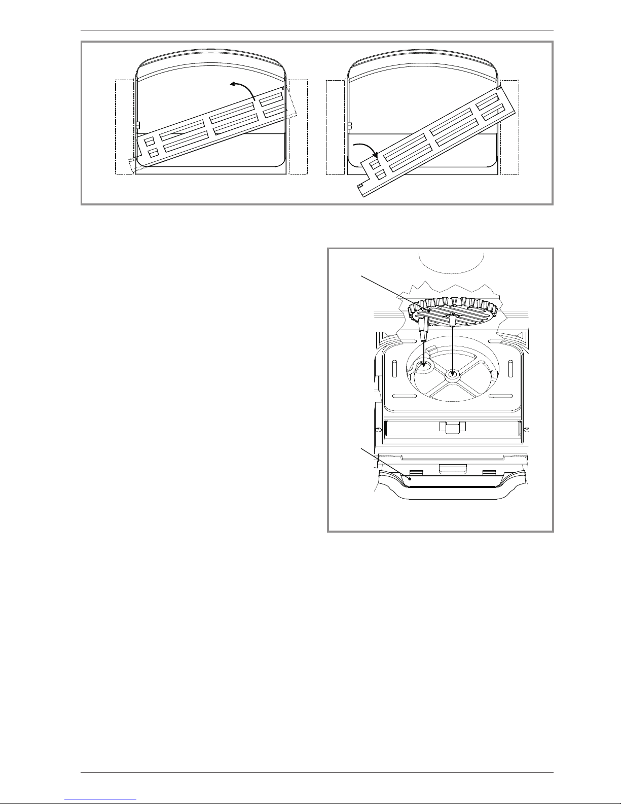
1
2
Figure 9 - Removing thefuel retainer
12
1
2
Figure 10 - Mounting the oscillating grate
and the ash tray
1Oscillating grate 2Ash tray

3.3. Instructions for use with solid fuel
3.3.1. lighting
Figure 8
-Slide the top air control (# B1) to the right. Open the
lower spin wheel.
-Lay firelighters or rolled up newspapers on the grate
with a reasonable quantity, if necessary, of dry kindling
wood. Place a small quantity of solid fuel on top.
-Light the newspaper or firelighters using a long taper
and close the door.
-When the fire is burning fiercely, add further fuel.
-When the stove body is hot, close the top air control by
sliding to the left.
-The burning rate can now be adjusted by rotating the
lower spin wheel.
3.3.2. Re-fuelling
-Open the lower spin wheel.
-Open the glass door and add fuel.
-Leave the lower spin wheel open for a few minutes to
allow the initial volatiles in the fuel to burn.
-Adjust the lower spin wheel to the desired position.
3.4. Cleaning
It is essential to keep the grate free from a heavy build
up of ashes. The Belfort is equipped with a grate
riddling device which is used to “shake” ashes off the
grate into the ash pan.
Whenever the stove is burning without life when the
lower spin wheel is open, use the riddling lever to clear
the grate of surplus ashes.
REMEMBER TO BURN SOLID FUEL CORRECTLY,
AlR SHOULD BE ALLOWED TO FLOW FROM THE
ASH PIT AREA THROUGH THE GRATE AND
THROUGH THE FUEL. IF THE GRATE OR ASH PAN
ARE CONGESTED, THE PERFOMANCE WILL BE
EFFECTED.
If burning solid fuel, always empty the ash pan at least
once a day or whenever it is full of ashes. Never allow
the ashpan to overfill allowing ash to be in contact with
the underside of the grate. If this condition is allowed,
the grate will wear out pre-maturely.
3.5. Maintenance of the stove
•The appliance must be regularly cleaned.
•Remove all deposits from the combustion chamber
and clean the grate area.
•Cleaning of the glass door can be done with a soft cloth
dampened with water and vinegar or potassium ; this
must be done when the appliance is cold ; then rinse
with clear water. Do not use abrasive cleaners.
•The “vitroceramic” glass will resists to temperatures of
up to 750 C. Should the glass break due to misuse, it
must be replaced by the manufacturers own product.
•All the casing parts can be cleaned using a soft cloth
either dry, or slightly damp. In case of condensation or
water splashes clean the parts before they dry out.
Warning ! The appearance of cracks when burning the
enamelled units is quite usual and tends to disappear
when the appliance is cooling down. It should not be
considered as a defect but rather as a patina of the
enamel which does not affect its quality nor its service
ability.
3.6. Recommendations
This room heater is a high heat producing appliance
and may cause severe burns if touched on the glass
front door, or on top directly over the burner - keep
children away.
FThe stove may still be hot even when fire has burnt
out.
3.7. Firebricks
When replacing firebricks, the fire must be
progressively increased to allow the firebricks to
expand normally and to dry up.
10 Technical manual “1174”
“BELFORT” - ref. 134 04 11 Instructions for user

3.8. Trouble Shooting
Problem Probable causes -Action
Fire difficult to start
Fire goes out
Wood green, too damp or poor
quality.
-Use the recommended fuel.
Logs are too big. -To light the fire, use small, very dry twigs. To maintain
the fire, use split logs.
Air starvation. -Open lower air control (coal) or top air control (wood).
Insufficient draught. þ-Check that the flue is not obstructed, sweep it if
necessary
-Seek advice from a chimney specialist.
Fire burns too quickly. Too much draught. -Ensure that the lower air control is closed (with wood
burning)
-Partially close the top air control lever.
Excessive draught. þ-Install a draught stabiliser. Consult your Dealer.
Poor quality wood. -Do not continuously burn small wood, sticks, bundles,
carpentry offcuts (plywood, pallets), etc.
Smokes when lighting up. Flue duct is cold. -Burn paper and kindling wood to increase heat.
Room is in decompression. -In houses equipped with mechanical ventilation, partly
open a window until the fire is well established.
Smokes while burning. Draught is insufficient. þ-Consult a chimney specialist.
-Check that the flue is not obstructed, sweep if
necessary.
Down draught. þ-Install an anti-down draught cowl. Consult your Dealer.
Room is in decompression. þ-In houses equipped with Mechanical Ventilation, an
outside air intake must be installed for the chimney.
Low heat output. Incorrect Fuels. -Use the recommended fuel.
Technical manual “1174” 11
“BELFORT” - ref. 134 04 11 Instructions for user
þ: This sign means that you should
ask for a qualified engineer to do the
work.

4. Spare parts
When ordering spare parts, specify the stove type and
serial number, including the colour index (on the
guarantee or identification plate), the name of the part
and the part number.
Example :
-Belfort wood stove : “Belfort”,
-model.: 134 04 11 Y,
-top : 352136 EF.
12 Technical manual “1174”
“BELFORT” - ref. 134 04 11 Spare parts
Y= 1340411Y;J= 1340411J;I= 1340411I;C= 1340411C;D= 1340411D;P= 1340411 P
N° Code Description ..........Type ........Y...J...I...C...D...P.....Qty
1 100917 Cam pin ...........12x20 M7 .......Y...J...I...C...D...P.....01
2 105123 Knob ..............191B ........Y...J...I...C...D...P.....01
3 105261 Firebrick...........328X70X35 ......Y...J ...I...C...D...P.....01
4 105262 Firebrick ..........207X207X35 ......Y...J...I...C...D...P.....02
5 110404 Hinge pin ............6X30 ........Y...J ...I...C...D...P.....02
7 134258 Bushing ........................Y...J...I...C...D...P.....01
8 181632 Adhesive rope .....................Y...J ...I...C...D...P....0,90 m
9 163196 Descriptive plate ....................Y...J ...I...C...D...P.....01
10 166003 Spring .............11x15 ........Y...J...I...C...D...P.....01
11 181614 Ceramic rope ........d.9,5mm.......Y...J ...I...C...D...P....1,92 m
13 181615 Ceramic rope ..........Ø12 ........Y...J...I...C...D...P....1,35 m
14 188798 Glass .............267X205 .......Y...J...I...C...D...P.....01
15 189103 Screw .............27x8x6 ........Y...J...I...C...D...P.....01
16 205368 Back panel .......................Y...J ...I...C...D...P.....01
17 222542 Flue baffle .......................Y...J ...I...C...D...P.....01
18 259015 Fixing plate ......................Y...J ...I...C...D...P.....04
19 262321 Heat shield ...........................J...I...C..............01
20 300118 EF Leg ...........................Y................D .........04
20 300118 79 Leg ...............................J......................04
20 300118 MP Leg....................................I..................04
20 300118 MK Leg .......................................C..............04
20 300118 RH Leg ................................................P.....04
21 300477 Base ..........................Y...J...I...C...D...P.....01
22 301526 EF Door lock........................Y ..........................01
22 301526 79 Door lock ............................J......................01
22 301526 MP Door lock ................................I..................01
22 301526 MK Door lock ....................................C..............01
22 301526 66 Door lock.........................................D .........01
22 301526 RH Door lock .............................................P.....01
23 301742 EF Air damper .......................Y................D .........01
23 301742 79 Air damper ...........................J......................01
23 301742 MP Air damper................................I..................01
23 301742 MK Air damper ...................................C..............01
23 301742 RH Air damper ............................................P.....01
24 301901 Oscillating grate ....................Y...J ...I...C...D...P.....01
25 303718 EF Blanking plate .....................Y................D .........01
25 303718 79 Blanking plate .........................J......................01
25 303718 MP Blanking plate ..............................I..................01
25 303718 MK Blanking plate ..................................C..............01
25 303718 RH Blanking plate ..........................................P.....01
26 303860 EF Flue collar .......................Y................D .........01
26 303860 79 Flue collar ...........................J ......................01
26 303860 MP Flue collar ................................I..................01
26 303860 MK Flue collar ....................................C..............01
26 303860 RH Flue collar ............................................P.....01
27 306268 Back wall........................Y...J...I...C...D...P.....01

Technical manual “1174” 13
“BELFORT” - ref. 134 04 11 Spare parts
$
" $
! %
!
!
"
'
$
'
#
%
! #
%
"
! !
&
"
! &
&
&
"
! !
"
#
#
#
! $
"
'
"
!
! '
! "
!
%
" !
" !
" #
" "
" %
" &
Figure 11 - Stove - exploded view

14 Technical manual “1174”
“BELFORT” - ref. 134 04 11 Spare parts
N° Code Description ..........Type ........Y...J...I...C...D...P.....Qty
Y= 1340411Y;J= 1340411J;I= 1340411I;C= 1340411C;D= 1340411D;P= 1340411 P
28 307432 Fuel retainer ......................Y...J...I...C...D...P.....01
29 309870 EF Front plate .......................Y................D .........01
29 309870 79 Front plate ...........................J ......................01
29 309870 MP Front plate................................I..................01
29 309870 MK Front plate....................................C..............01
29 309870 RH Front plate ............................................P.....01
30 309989 EF Main door .......................Y ..........................01
30 309989 79 Main door ............................J ......................01
30 309989 MP Main door ................................I..................01
30 309989 MK Main door ....................................C..............01
30 309989 66 Main door ........................................D .........01
30 309989 RH Main door.............................................P.....01
31 310724 EF R. side panel......................Y................D .........01
31 310724 79 R. side panel ..........................J......................01
31 310724 MP R. side panel ..............................I..................01
31 310724 MK R. side panel ..................................C..............01
31 310724 RH R. side panel ...........................................P.....01
32 310822 EF L. side panel ......................Y................D .........01
32 310822 79 L. side panel ..........................J ......................01
32 310822 MP L. side panel...............................I..................01
32 310822 MK L. side panel...................................C..............01
32 310822 RH L. side panel ...........................................P.....01
33 315603 Air duct.........................Y...J...I...C...D...P.....01
34 319731 Grate support .....................Y...J ...I...C...D...P.....01
35 327801 Clamp .........................Y...J...I...C...D...P.....01
36 327902 EF Ash-tray ........................Y................D .........01
36 327902 79 Ash-tray.............................J ......................01
36 327902 MP Ash-tray .................................I..................01
36 327902 MK Ash-tray .....................................C..............01
36 327902 RH Ash-tray .............................................P.....01
37 352136 EF Top plate ........................Y................D .........01
37 352136 79 Top plate ............................J ......................01
37 352136 MP Top plate ................................I..................01
37 352136 MK Top plate ....................................C..............01
37 352136 RH Top plate .............................................P.....01
38 237423 Reducing plate.....................Y...J ...I...C...D...P.....01
39 458404 Rod...........................Y...J...I...C...D...P.....01
40 624040 Ash-pan ........................Y...J...I...C...D...P.....01
41 613302 60 Air control flap .....................Y...J ...I...C...D...P.....01
42 808001 ED Hand tool........................Y...J...I...C...D...P.....01
43 325304 Reducing plate.....................Y...J ...I...C...D...P.....02
44 161027 Touch-up paint .........................J ......................01
44 161048 Touch-up paint .............................I..................01
44 161032 Touch-up paint .................................C..............01
44 161039 Touch-up paint ..........................................P.....01
45 988839 Main door complete ..................Y ..........................01
45 988841 Main door complete ......................J ......................01
45 988842 Main door complete ...........................I..................01
45 988843 Main door complete ...............................C..............01
45 988889 Main door complete ...................................D .........01
45 988897 Main door complete .......................................P.....01
46 181607 Ceramic rope ........d.9,5mm.......Y...J ...I...C...D...P....0,50 m
47 300122 High leg (optional) ...................Y................D .........04
48 142881 Gasket .........................Y...J...I...C...D...P.....04

§Guarantee certificate §
§Legal guarantee
The specifications, dimensions and information shown on
our documents are provided for information purposes only
and under no circumstances are binding upon the vendor.
With the aim of constantly improving our equipment, all
modifications considered as necessary by our departments
may be made without notice.
The provisions of the present guarantee certificate are not
excluding or limiting the owner of the equipment’s rights,
concerning the legal guarantee regarding faults or hidden
vices which applies in all circumstances, in the conditions
detailed in articles 1641and following of the civil code, and in
the country in which the equipment was purchased.
§Contractual guarantee
Our equipment is guaranteed against faults and hidden
vices subject to the following conditions:
1) Installation and adjustment of the device by a
professional installer.
2) Observance of the instructions provided in our technical
documents and our installation/adjustment instructions.
3) The installation, use and maintenance of the device
carried out in conformity with the applicable standards
and legislation, and with the indications provided in the
technical instructions accompanying the device.
This guarantee covers the replacement, in our factory, of
parts recognised as being defective from the outset by our
“Guarantee Inspection” Department. Carriage and labour is
at the user’s cost. Moreover, if the repair or replacement of
parts covered by the guarantee is found to be too costly
vis-a-vis the price of the appliance, the decision to replace or
repair the appliance will be taken by the vendor.
Our guarantee is for 2 (two) years for all appliances, with the
exception of closed combustion fireplace and inserts for
which our guarantee is 5 (five) years excluding the following:
1) Indicator lights, fuses, electrical elements and fans.
2) Parts subject to wear or in contact with high
temperatures namely: soles and burner grills, bottom
plates baffles, ash pans, paintwork and surface
treatments for decorative parts. Also excluded from this
guarantee are seals and windows.
3) Any damage which may result from the use of the
appliance with a fuel other than that stipulated in our
instructions.
4) Damage occurring to parts caused by elements outside
the appliance (down draught, storm damage, damp,
abnormal pressure or vacuum, heat shocks, etc.).
5) Damage to electrical parts caused by plugging in and
using the appliance on a mains system, the voltage of
which (measured at the entrance to the appliance) is
10% above or below the nominal voltage of 220 V.
§Exclusion of liability
In the case of a product manufactured at the client’s request,
under no circumstances may we, as a subcontractor, be
considered liable vis-a-vis the client or third parties for
defects arising from the installation or a design fault with the
item in question.
*Name and address of the installer : _____________________________
______________________________________________
(Telephone : _______________________________________
*Name and address of the customer : _____________________________
______________________________________________
Date of installation : __ __ / __ __ /__ __ __ __
Model of the appliance : q134 04 11
Color : qYqJqIqCqDqP
Serial number : ___ ___ ___ ___ ___ ___
• This certificate has to be completed and kept carefully.
In case of claims, send a copy of this to :
STAUB FONDERIE
BP 73, 59660 MERVILLE, FRANCE.
Other manuals for 134 04 11
1
Table of contents
Popular Wood Stove manuals by other brands


RAIS
RAIS attika NEXO 100 GAS installation guide

WoodPro
WoodPro WS-TS-1500 owner's manual

Contura
Contura C 586W installation instructions

Palazzetti
Palazzetti EVA GENERAL INFORMATION - WARNINGS - INSTALLATION - MAINTENANCE

Lopi
Lopi 1250 Republic owner's manual

Panadero
Panadero CAPRI 3V Usage and maintenance instructions