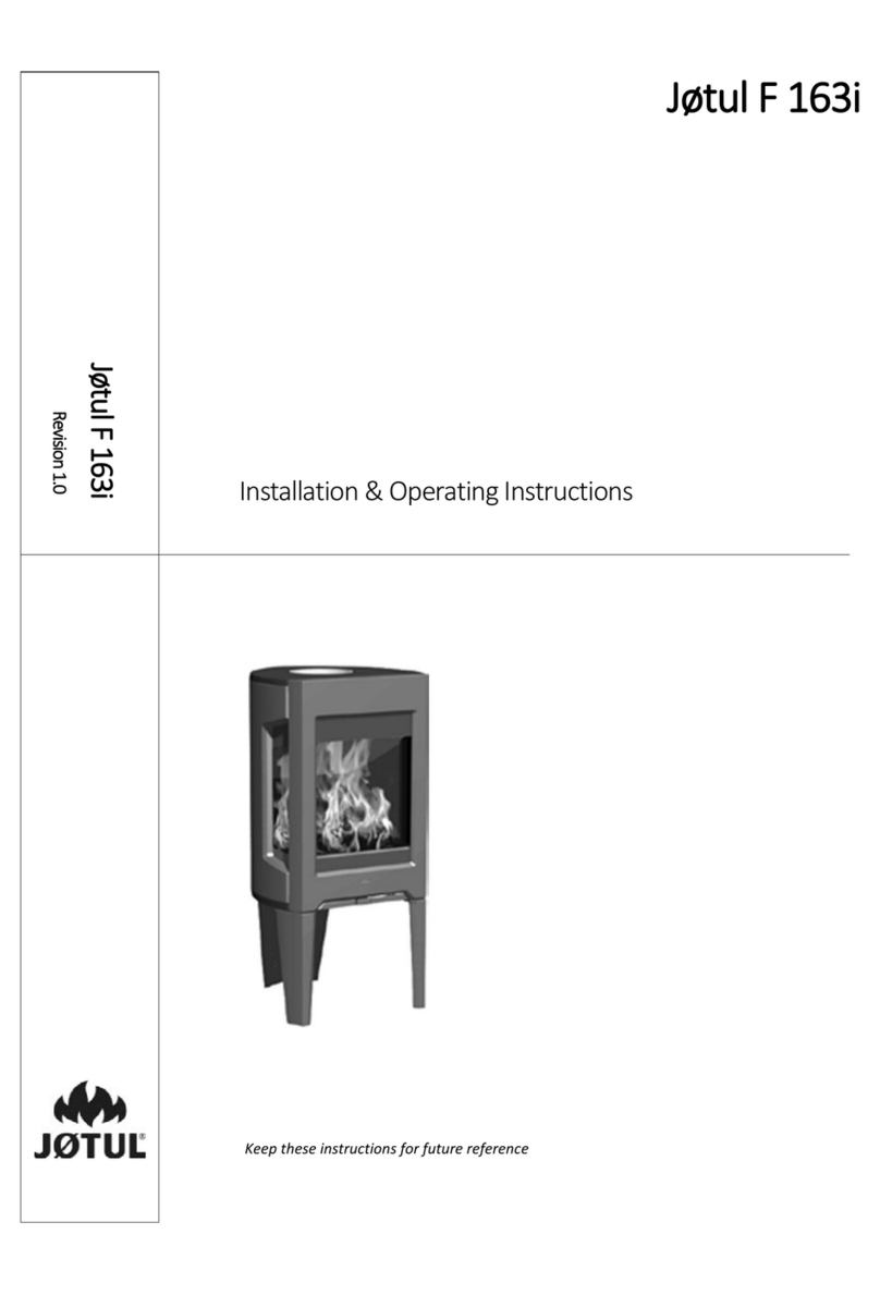
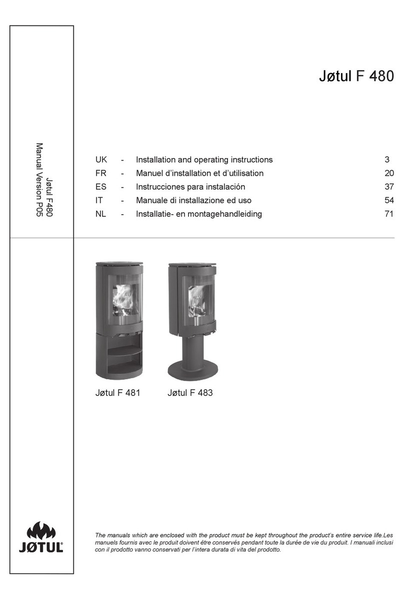
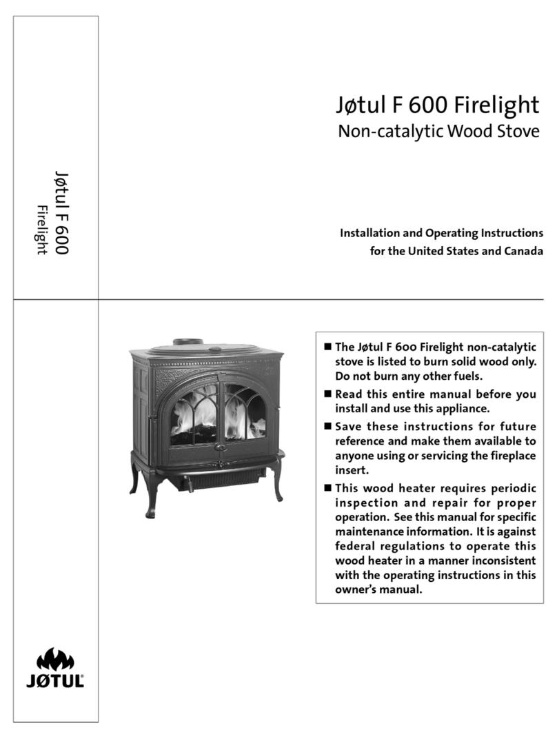
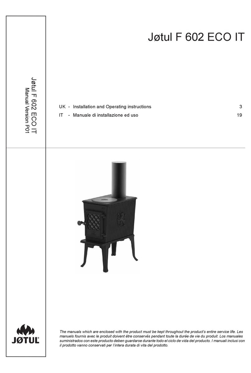
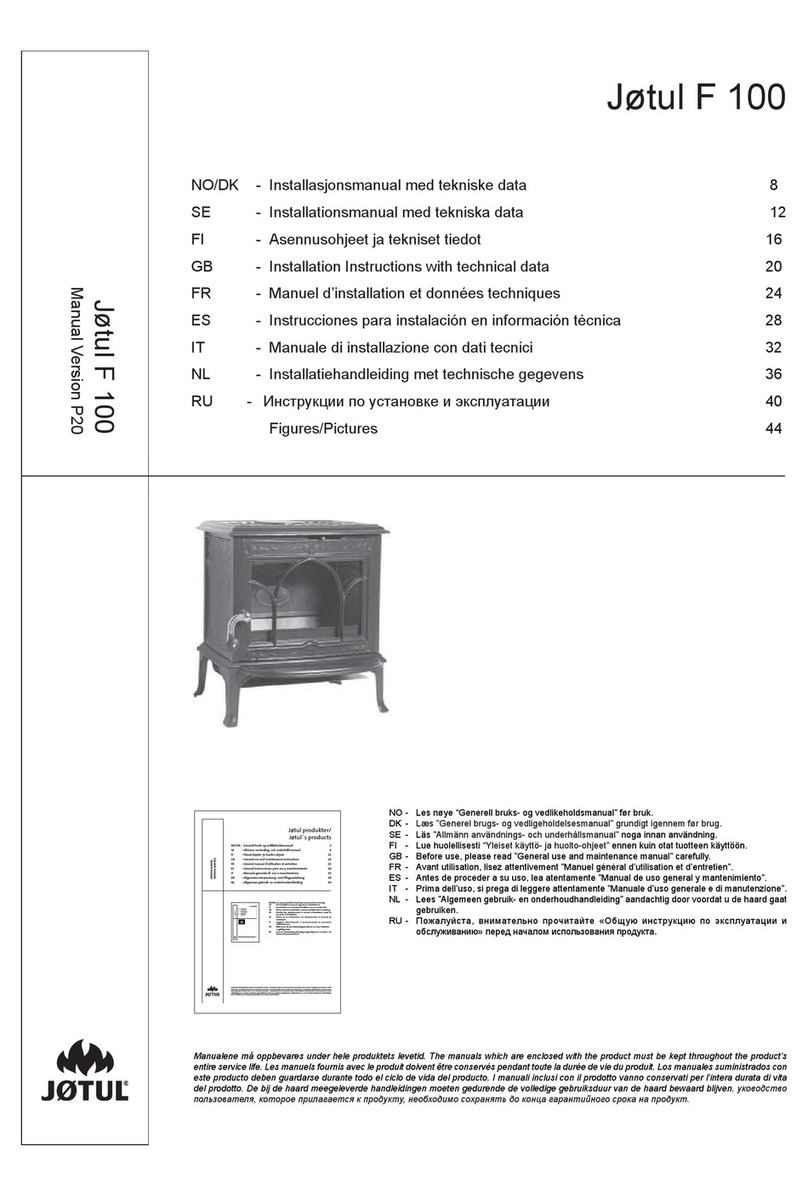
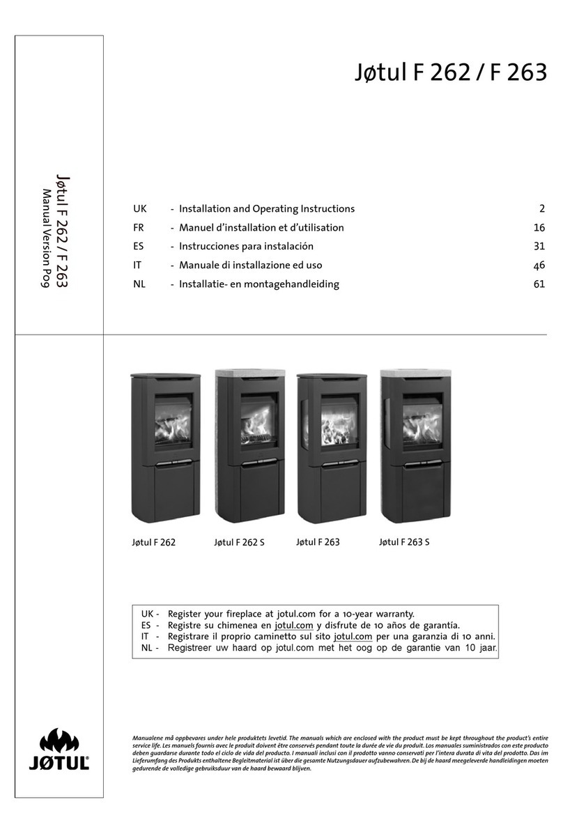
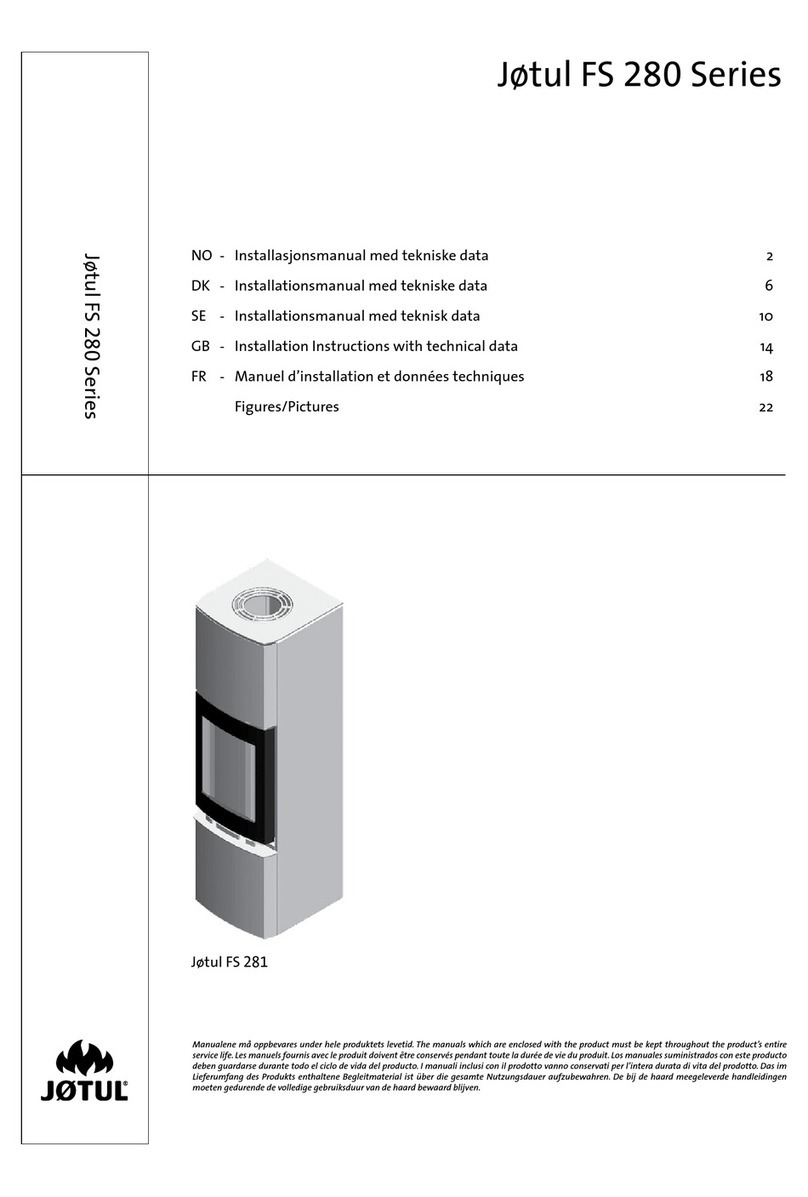
Jøtul F 400 Castine User manual

Jøtul F 400 Castine
Save these instructions and make them available to anyone using or servicing the stove.
Jøtul F 400 Castine
Non-catalytic Wood Stove
Installation and Operation Instructions
for the U.S. and Canada

2
139680-R00 F 400 Castine May 2015
Standards
The Jøtul F 400 Castine solid fuel heater has been tested
and listed to :
U.S. Standards: ANSI/UL 737 and ANSI/UL 1482.
Canadian Standards:
CAN/ULC-S627-M00 and CAN/ULC-S628-M93
Certified Safety Tests performed by:
Intertek Testing Services, Middleton, Wisconsin U.S.A.
Manufactured by:
Jøtul North America, Inc.
55 Hutcherson Drive
Gorham, Maine 04038, USA
and
Jøtul AS, P.O. Box 1411, Fredrikstad, Norway
Distributed by:
Jøtul North America, Inc.
55 Hutcherson Drive
Gorham, Maine 04038, USA
Check Building Codes
When installing,operating and maintaining your Jøtul
F 400 woodstove, follow the guidelines presented in
these instructions,and make them available to anyone
using or servicing the stove.
Your city, town, county or province may require a
building permit to install a solid fuel burning appliance.
In the U.S., the National Fire Protection Association’s
Code, NFPA 211, Standards for Chimneys, Fireplaces,
Vents and Solid Fuel Burning Appliances, or similar
regulations, may apply to the installation of a solid fuel
burning appliance in your area.
In Canada, the guideline is established by the CSA
Standard, CAN/CSA-B365-M93, Installation Code for
Solid-Fuel-Burning Appliances and Equipment.
Always consult your local building inspector or
authority having jurisdiction to determine what
regulations apply in your area.
Heat Output*: Under specific test conditions, this
heater has been shown to deliver heat ranging from
11,300 to 27,800 BTU’s.
Efficiency*: 63%
CO Emissions: N/A
Pariculate Emissions: 3.8 g/h
* Default values per previous Federal Register 40 CFR Part
60, Subpart AAA.
EPA validated efficiency and CO values were unavailable
at the time of this printing. These values will be made
available in the manual and on the Jotul website (www.
jotul.us) for your reference in the near future.
Combustion Specifications
This heater meets the 2015 U.S.
Environmental Protection Agency’s
emission limits for wood heaters
manufactured after May 15, 2015.
This heater may not to be sold after
May 15, 2020.
WARNING !
THIS WOOD HEATER HAS A MANUFACTURER-
SET MINIMUM LOW BURN RATE THAT MUST
NOT BE ALTERED. IT IS AGAINST FEDERAL
REGULATIONS TO ALTER THIS SETTING
OR OTHERWISE OPERATE THIS WOOD
HEATER IN A MANNER INCONSISTENT WITH
OPERATING INSTRUCTIONS IN THIS MANUAL.
See Sect. 5.0 of this manual for important information
regarding the safe, proper, and most efficient operation
of your stove.
Installation and Operation Instructions
for USA/Canada
Safety Notice:If this solid fuel room heater is not properly
installed, a house fire may result. For your safety, follow
the installation directions. Contact local building or fire
officials about restrictions and installation inspection
requirements in your area.
This manual describes the installation and operation of
the Jøtul F 400 non-catalytic wood heater.Read this entire
manual before you install and use your new stove. Save
these instructions for future reference.
This wood heater needs periodic inspection and repair for
proper operation. See this manual for specific information.
It is against federal regulations to operate this wood
heater in a manner inconsistent with the operating
instructions in this owner’s manual.

3
139680-R00 F 400 Castine May 2015
Table of Contents
Safety Notices
1.0 Installation
1.1 Assembly Before Installation............................................. 4
1.2 Flue Collar Reversal .............................................................. 4
1.3 Chimney Connector ............................................................. 4
2.0 Chimney Requirements
2.1 Masonry Chimneys ............................................................. 4
2.2 Prefabricated Chimneys...................................................... 5
2.3 Chimney Height.................................................................... 5
2,4 Wall Pass-Throughs.............................................................. 5
3.0 Connecting to the Chimney
3.1 Masonry Chimney ............................................................... 6
3.2 Hearthmount / Fireplaces.................................................. 6
3.3 Prefabricated Chimneys...................................................... 6
4.0 Clearances to Combustibles
4.1 Floor Protection..................................................................... 6
4.2 Clearances to Walls and Ceilings...................................... 6
4.3 Using Shields to Reduce Clearances ............................... 6
4.4 Alcove Installation ............................................................... 7
4.5 Mobile Home Installation ................................................. 7
5.0 Operation
5.1 Combustion Efficiency......................................................... 7
5.2 CO Emissions ......................................................................... 7
5.3 Wood Fuel and Performance ............................................. 7
5.4 Air Flow and Control ............................................................ 8
5.5 Breakin Procedure ................................................................ 8
5.6 Starting / Maintaining the Fire......................................... 8
5.7 Adding Fuel ............................................................................ 9
6.0 Maintenance
6.1 Ash Removal........................................................................... 9
6.2 Glass Care ............................................................................... 9
6.3 Glass Removal ....................................................................... 9
7.0 General Maintenance
7.1 Gaskets.................................................................................... 10
7.2 Gasket replacement............................................................. 10
7.3 Chimney System ................................................................... 10
8.0 Accessories..................................................................... 11
9.0 Illustrations
Clearance Diagrams .................................................................... 14
Clearance Chart ........................................................................... 15
Figures............................................................................................. 16 - 18
Parts Diagram and List................................................................ 19 - 20
Appendix A - Alternate Floor Protection ............................... 20
10.0 Warranty ............................................................................. 21
Safety Notices
• BURN SOLID, NATURAL WOOD FUEL ONLY. DO NOT
BURN ANY OTHER FUEL.
• DO NOT USE CHEMICALS OR FLUIDS TO START A FIRE.
DO NOT BURN GARBAGE OR FLAMABLE FUELS.
• DO NOT USE A GRATE OR ELEVATE THE FIRE. BUILD THE
FIRE DIRECTLY ON THE HEARTH.
• IF THIS ROOM HEATER IS NOT PROPERLY INSTALLED, A
HOUSE FIRE MAY RESULT.TO REDUCE THE RISK OF FIRE,
FOLLOW THE INSTRUCTIONS IN THIS MANUAL.FAILURE
TO FOLLOW THESE INSTRUCTIONS MAY RESULT IN
PROPERTY DAMAGE, BODILY INJURY, OR LOSS OF LIFE.
• CONTACT LOCAL BUILDING OR FIRE OFFICIALS ABOUT
RESTRICTIONS AND INSTALLATION INSPECTION
REQUIREMENTS IN YOUR AREA.
• ANY EXISTING CHIMNEY SYSTEM MUST BE INSPECTED
BEFORE INSTALLATION OF THIS APPLIANCE.
• DO NOT CONNECTTHIS STOVETO ANY AIR DISTRIBUTION
DUCT OR SYSTEM.
• EXTREMELY HOTWHILE IN OPERATION! KEEP CHILDREN,
CLOTHING, AND FURNITURE AWAY. CONTACT WILL
CAUSE SKIN BURNS. USE A CHILD GUARD SCREEN TO
PREVENT ACCIDENTAL CONTACT BY SMALL CHILDREN.
• INSTALL SMOKE DETECTORS IN THE LIVING AREA AND
BEDROOMS OF YOUR HOME. TEST THEM REGULARLY
AND INSTALL FRESH BATTERIES TWICE ANNUALLY.
WHEN INSTALLED IN THE SAME ROOM AS THE STOVE,
A SMOKE OR CARBON MONOXIDE DETECTOR SHOULD
BE LOCATED AS FAR FROM THE STOVE AS POSSIBLE TO
PREVENTTHE ALARM SOUNDING WHEN ADDING FUEL.
• Avoid creating a low pressure condition in the room
where the stove is operating. Be aware that operation
of an exhaust fan or clothes dryer can create a low
pressure area and consequently promote flow reversal
through the stove and chimney system. In some cases,
the optional Outside Air Kit #154335 can be used to
alleviate this condition. The chimney and building,
however, always work together as a system - provision
of outside air,directly or indirectly to an atmospherically
vented appliance will not guarantee proper chimney
performance.Consult your local Jøtul authorized dealer
regarding specific installation/performance issues.
• Jøtul strongly recommends that this stove be installed
by a professional solid fuel technician, or that you
consult one if you do the work yourself. Also, consult
your insurance company regarding any other specific
requirements.

4
139680-R00 F 400 Castine May 2015
1.0 Installation
If this solid fuel room heater is not properly installed, a house
fire may result.For your safety, follow the installation directions
exactly. Contact the local building or fire officials about
restrictions and installation inspection requirements in your area.
Your local officials have final authority in determining if a
proposed installation is acceptable.Any requirement by the local
authority having jurisdiction that is not specifically addressed in
this manual,defaults to NFPA 211, and local codes in the U.S.or in
Canada, CAN/CSA-B365-M and local codes.
1.1 Assembly Before Installation
Unpack the Stove
Inspect the stove for damage. Contact your dealer immediately
if any damage is found. Do not install the stove if any damage
is evident.
Contents:
• Inspection Cover (Not for use in US/Canada)
• Bottom Heat Shield
• Door Handle
• Hardware Bag
1.2 Flue Collar Reversal
The Flue Collar is oriented in the Top Exit position. If a Rear Exit
position is required, remove the two mounting bolts, and turn
the collar 180 degrees. Secure the collar using the same bolts,
nuts and washers.
1.3 Chimney Connector
Use 6”single wall or listed 6”double-wall stovepipe to connect the
stove to the chimney. Single wall stovepipe must be black iron or
stainless steel and have a minimum thickness of 24 gauge. Do not
use aluminum or galvanized steel pipe for chimney connection
- these materials are not suitable for use with solid fuel.
Follow these guidelines regarding chimney connector
construction:
• DO NOT USE CHIMNEY CONNECTOR AS A CHIMNEY. IT IS
INTENDED ONLY TO BE USED A CONNECION DEVICE.
• Each connector section must be oriented with the male
(crimped) end pointing toward the stove. See fig. 2.
• Secure all connector joints with three sheet metal screws.
• For the best performance, the chimney connector should be
as short and direct as possible, including no more than two
90° elbows.
• The maximum vertical run of single wall stovepipe should not
exceed 10 ft. (305 cm). The maximum horizontal run should
not exceed 3 ft. (92 cm) with a 1/4” rise per foot.
• No part of the chimney connector may pass through an attic
or roof space, closet or other concealed space, or through
a floor or ceiling. All sections of the chimney connectors
must be accessible for cleaning. Where passage through a
wall or partition of combustible construction is desired, the
installation must conform with NFPA 211 or CAN/CSA-B365,
and is also addressed in this manual.
• DO NOT CONNECT THIS HEATER TO ANY CHIMNEY SERVICING
ANOTHER APPLIANCE.
2.0 Chimney Requirements
There are two types of chimneys suitable for the Jøtul F 400 :
1. A code-approved masonry chimney with a ceramic tile or
listed steel flue liner.
2. A prefabricated chimney complying with the requirements
for Type HT (2100°F) chimneys per UL 103 or ULC S629.
The chimney size should not be less than the cross-sectional area
of the flue collar,and not more than three times greater than the
cross-sectional area of the flue collar.
When selecting a chimney type and the location for the chimney
in the house, keep this in mind: It is the chimney that makes the
stove work, not the stove that makes the chimney work. It is
the temperature differential between the chimney and the air
outside that initiates and maintains the draft necessary to pull
air into the stove to support combustion.
Several factors beside stove design affect draft strength;chimney
height, cross-sectional area, flue temperature, environmental
conditions such as weather and local geography, as well as the
proximity of surrounding trees or buildings. Weak draft, for
whatever reason, can cause smoke leakage into the room and
poor overall performance.
A short masonry chimney on the exterior of a house will give
the poorest performance. This is because it can be very difficult
to warm the chimney enough to generate adequate draft. In
extremely cold climates,it may be necessary to reline the chimney
or extend its height to help establish draft.
A tall, interior masonry chimney is easier to keep warm and will
perform the best under a variety of weather and environmental
conditions.
The followingguidelines give the necessary chimney requirements
based on the national code (ANSI-NFPA 211 for the US. And CSA
CAN-B365 for Canada). However, many local codes differ from
the national code to take into account climate,altitude, or other
factors. Your local building inspector is the final approving
authority. Consult them prior to installation.
DO NOT CONNECT THIS HEATER TO ANY AIR DUCT OR HEAT
DISTRIBUTION SYSTEM.
2.1 Masonry Chimneys
When installing the Jøtul F 400 into a masonry chimney you
must conform to all of the following guidelines:
• The chimney flue size should not be less than the cross-
sectional area of the stove flue collar.
• The cross-sectional area of the flue of a chimney with no
walls exposed to the outside below the roofline shall not be
more than three times the crosssectional area of the stove
flue collar.
• The cross-sectional area of the flue of a chimney with one or
more walls exposed to the outside below the roofline shall
not be more than two times the cross-sectional area of the
stove flue collar.
• Larger chimney flues should be relined with a listed or
codeapproved liner.
• The masonry chimney must have a fireclay liner or equivalent,
with a minimum thickness of 5/8” (14 mm) and must be

5
139680-R00 F 400 Castine May 2015
installed with refractory mortar. There must be at least 1/2”
(12.7 mm) air space between the flue liner and chimney wall.
• The fireclay flue liner must have a nominal size of 8”X 8”(20
cm x 20 cm), and should not be larger than 8”X 12” (20 cm x
30 cm). A round fireclay liner must have a minimum inside
diameter of 6”(15 cm) and maximum inside diameter of 8”(20
cm). A larger chimney should be relined with an appropriate
code approved liner.
• Brick or modular block must be a minimum of 4” (10 cm)
nominal thickness. Stone construction must be at least 12”
(30 cm) thick.
• A newly-built chimney must conform to local codes, or, in
their absence, must comply with national regulations.
• An existing chimney must be inspected by a professional
licensed chimney sweep, fire official,or code officer to ensure
that the chimney is in proper working order.
• No other appliance may be vented into the same flue.
• An airtight clean-out door should be located at the base of
the chimney.
2.2 Prefabricated Chimneys
A prefabricated metal chimney must be tested and listed for
use with solid fuel burning appliances. High Temperature (HT)
Chimney Standard UL 103 for the U.S. and High Temperature
Standard ULC S-629 for Canada.
The manufacturer’s installation instructions must be followed
precisely. Always maintain the proper clearance to combustibles
as established by the pipe manufacturer. This clearance is usually
a minimum of 2”, although it may vary by manufacturer or for
certain chimney components.
2.3 Chimney Height
The chimney must be at least 15 ft (4.57 m) high and 3 feet (92
cm) higher than the highest point where it passes through the
roof, and at least 2 feet (61 cm) higher than the highest part of
the roof or structure that is within 10 feet (3.05 m) of the chimney,
measured horizontally. See figure 3.
Chimneys shorter than 15 feet (4.57 m) may not provide adequate
draft. Inadequate draft can result in smoke spillage when loading
the stove,or when the door is open. Poor draft can also cause back
puffing (ignition of gas build-up inside the firebox) and sluggish
performance.The minimum height does not, in itself,guarantee
proper chimney performance.
Excessive chimney height can promote over-strong draft resulting
in extreme stove temperatures and uncontollable fires.Your Jøtul
dealer is an expert resource to consult regarding draft issues or
other performance-related questions.
2.4 Wall Pass-Throughs
In the U.S.
The National Fire Protection Association’s publication, NFPA
211, Standard for Chimneys, Fireplaces, Vents and Solid Fuel
Burning Appliances permits four methods for passing through
a combustible wall. Before proceeding with any method be sure
to consult with your local building officials to discuss any local
code requirements.
Common Method / U.S.
• See figures 4 and 5. Remove all combustible materials from
the pass-through area ( around the chimney connector), a
minimum 12” (30.5 cm). A 6” (15.2 cm) diameter connector
will require a 31”x 31” (78.7 x 78.7 cm) square opening.
• The opening must be filled with at least 12” (30.5 cm) of
brick around a fireclay liner. The liner must be ASTM C35 or
equivalent,having a minimum wall thickness of 5/8”(16 mm).
• The Pass-through must be at least 18” (45.7 cm) from
combustible ceiling materials.
• It will be necessary to cut wall studs, install headers, and
construct a sill frame to maintain the proper dimensions and
to support the weight of the brick.
• The bricks must be solid brick with a minimum of 3 ½ inches
thick (nominal 4” / 102 mm).
• Refractory mortar must be used at the junction of the chimney
and the pass-through liner.The pass-through liner must not
penetrate the chimney liner beyond the inner surface of the
chimney liner. Use extreme care when constructing the hole
in the chimney liner as the tiles can shatter easily.
In Canada
The installation must conform to CAN/CSA-B365, Installation
Code for Solid Fuel Burning Appliances and Equipment. Before
proceeding be sure to consult your local building inspector.
Common Method / Canada
• This method requires the removal of all combustible materials
from at least 18” (45.7 cm) around the chimney connector’s
proposed location. A 6” round liner requires a minimum
opening 43” x 43” (109.2 x 109.2) square.
• Locate the pass-through at least 18”from combustible ceiling
materials.
• The space that is cleared of combustible materials must
remain empty. Sheet metal panels can be used to cover the
area. However, when using a panel on both sides of the wall,
each cover must be installed on noncombustible spacers at
least 1”from the wall. If one panel of sheet metal is to be used
it may be installed flush to the wall.
See section 5.3.1 and 5.3.2 of CAN/CSA - B365-M91. Consult your
local building inspector, authorized Jøtul Dealer, NFPA 211 in the
U.S. or CAN/CSA-B635 in Canada for other approved wall pass-
through methods.
Table of contents
Other Jøtul Wood Stove manuals

Jøtul
Jøtul Loke Corten User manual

Jøtul
Jøtul F 400 User manual

Jøtul
Jøtul Cube 200 GG WS User manual

Jøtul
Jøtul F 602 CB User manual

Jøtul
Jøtul F 600 User manual

Jøtul
Jøtul Oslo F 500 User manual

Jøtul
Jøtul FS 380 Series Instruction manual

Jøtul
Jøtul F 164 User manual

Jøtul
Jøtul F 400 ECO User manual

Jøtul
Jøtul Woodstove F 400 User manual
Popular Wood Stove manuals by other brands

WoodPro
WoodPro WS-TS-1500 owner's manual

Contura
Contura C 586W installation instructions

Palazzetti
Palazzetti EVA GENERAL INFORMATION - WARNINGS - INSTALLATION - MAINTENANCE

Lopi
Lopi 1250 Republic owner's manual

Panadero
Panadero CAPRI 3V Usage and maintenance instructions

Ventis
Ventis HES350 owner's manual