Heat King HK150 User manual

HK150
Operation Manual
Wayne Burner
Part # 200102
Date # July 2020

As a new customer of Heat King we would like to welcome you! We are looking
forward to providing you with technical support for your Heat King unit. Whatever you
need we are here to help.
Ways to contact us for support
By Phone : 1-800-661-0304
The main Technical support phone line is staed monday-friday 7:00 AM to 4:30
PM CST excluding Manitoba statuatory holidays.
After hours support
Calls received outside of regular hours are directed to the On-call technician. Af-
ter hours support is reserved for issues that cannot wait until the next business day
for resolution. If no answer please leave a message and we will get back to you as
soon as possible.
Feel free to email us at any time with technical questions or parts inquiries.
Please include the year make and model of your Heat King if you have a specic
question about your machine so we can better help you. If it is an emergency please
call 1-800-661-0304
For more information please visit our website
www.heat-king.ca
WARNING
CALIFORNIA - Proposition 65 Warning
Engine exhaust and some of its constituents and some dust
created by power sanding, sawing, grinding, drilling and
other construction activities contains chemicals known to the
State of California to cause cancer, birth defects and other
reproductive harm.
Some examples of these chemicals are:-
Lead from lead-based paints
Crystalline silica from bricks
Cement and other masonry products
Arsenic and chromium from chemically
treated lumber
Your risk from these exposures varies, depending on how
often you do this type of work. To reduce your exposure to
these chemicals:
ALWAYS work in a well ventilated area, and work with
approved safety equipment, such as dust masks that are
specially designed to lter out microscopic particles.
23

Table of contents
Title Pages
Ways to contact us 2
Warning 3
Safety 5-11
Introduction 12
Training sign o 13
Vin Number Location 14
Warranty 15-16
How it works 17
Protective devices 18
Controls 19-23
Set up 24-25
Operating procedures 26-27
Maintenance 28-37
Service parts 38
Troubleshooting 39-40
Lifting instructions 41-42
Specications 43
MSDS 44-53
Schematics 54
Accidents Disable and Kill
Accidents Cost
Accidents Can Be Avoided
Why is SAFETY important to you?
3 Big Reasons
ous situation that, if not avoided, will
result in death or serious injury. This
signal word is to be limited to the most
extreme situations, typically for ma-
chine components that, for functional
purposes, cannot be guarded.
Indicates a potentially hazardous situa-
tion that, if not avoided, could result in
death or serious injury, and includes
hazards that are exposed when guards
are removed. It may also be used to
alert against unsafe practices.
Indicates a potentially hazardous situa-
tion that, if not avoided, may result in
minor or moderate injury. It may also
be used to alert against unsafe prac-
tices.
SIGNAL WORDS:
Note the use of the signal words DANGER,
The Safety Alert symbol identies
important safety messages on the
Tamarack Heat King and in the
manual. When you see this symbol,
be alert to the possibility of personal
injury or death. Follow the instruc-
tions in the safety message.
This Safety Alert symbol means
ATTENTION! BECOME ALERT!
YOUR SAFETY IS INVOLVED!
WARNING and CAUTION with the safety
messages. The appropriate signal word for
each message has been selected using the
following guide-lines:
SAFETY
SAFETY ALERT SYMBOL
DANGER - Indicates an imminently hazard-
WARNING -
CAUTION -
45

Safety, Installation & Operation
SAFETY
YOU are responsible for the SAFE operation and
maintenance of your Tamarack Industries Heat
King. YOU must ensure that you and anyone else
who is going to operate, maintain or work around
the Heat King be familiar with the operating and
maintenance procedures and related SAFETY
information contained in this manual. This manual
will take you step-by-step through your working
day and alerts you to all good safety practices that
should be adhered to while operating the Heater.
Remember, YOU are the key to safety. Good
safety practices not only protect you but also
the people around you. Make these practices a
working part of your safety program. Be certain
that EVERYONE operating this equipment is
familiar with the recommended operating and
maintenance procedures and follows all the safety
precautions. Most accidents can be prevented.
Do not risk injury or death by ignoring good safety
practices.
• Heater owners must give operating instruc-
tions to operators or employees before allow-
ing them to operate the machine, and at least
annually thereafter.
• The most important safety device on this
equipment is a SAFE operator. It is the opera-
tor’s responsibility to read and understand
ALL Safety and Operating instructions in the
manual and to follow these. Most accidents
can be avoided.
• A person who has not read and understood
all operating and safety instructions is not
qualied to operate the machine. An untrained
operator exposes himself and bystanders to
possible serious injury or death.
• Do not modify the equipment in any way.
Unauthorized modication may impair the
function and/or safety and could aect the life
of the equipment.
• Think SAFETY! Work SAFELY!
GENERAL SAFETY
Only trained competent persons shall operate
the Heater. An untrained operator is not qualied
to operate the machine.
Have a rst-aid kit available for
use, should the need arise and
know how to use it.
Do not allow riders.
Have a re extinguisher available for use
should the need arise and know how to
use it.
Wear appropriate protective gear. This
list includes, but is not
limited to:
- A hard hat
- Protective boots with
slip resistant soles
- Protective goggles
- Heavy gloves
- Hearing protection
Place all controls in their OFF position,
disconnect power cords and wait for all moving
parts to stop before servicing, adjusting or
maintaining
Wear appropriate hearing protection
when operating for long periods of
time.
Wear protective gloves
Ventilation ~ Never operate in a poorly
ventilated or enclose area. Avoid
prolonged breathing of exhaust
gases.
2.
3.
4.
5.
6.
7.
8.
9.
10.
1 . R e a d a n d u n d e r s t a n d t h e
Operator's manual and all
safety signs before
operating, maintaining,
adjusting, servicing or
cleaning the Heater.
ELECTRICAL SAFETY
1. Place all controls in their OFF position, discon-
nect power cords and wait for all moving parts to
stop before servicing, adjusting or maintaining.
2. Place all controls in their OFF position before
plugging in power cords.
3. Keep all electrical components in good repair
before starting.
4. Do not lay power lines or connectors in water
or on a wet surface. Dry connectors and raise
power lines out of the water before and during
operation.
5. Do not operate machine if there are electrical
malfunctions. Correct problem before resuming
work.
11. Hot surface ~ Avoid contact with
hot exhaust and glycol system.
Allow to cool before performing repairs
or service.
12. Electrocution Hazard ~ Always use proper size
grounded extension cord. Inspect all extension
cords for cuts, frayed wires and broken connectors.
Do not use cords if not in good condition.
13. Fire Hazard ~ Do not operate
machine in the vicinity of open
ames, sparks or while
smoking.
14. Explosion Hazard ~ Battery
Take care when handling battery
(if installed)
TIRE SAFETY
1. Failure to follow proper procedures when
mounting a tire on a wheel or rim can produce
an explosion which may result in serious injury
or death.
2. Do not attempt to mount a tire unless you have
the proper equipment and experience to do the
job.
3. Have a qualied tire dealer or repair service
perform required tire maintenance.
4. Torque wheel nuts to 165 ft-lbs
STORAGE SAFETY
1. Store unit in an area away from human
activity.
2. Do not permit children to play on or around the
stored Heater.
FUEL SAFETY
Danger: To avoid possible injury, re, or explo-
sion, please read and follow these instruc-
tions.
1. Handle fuel with care. It is highly ammable.
2. Allow burners to cool for 5 minutes before
refueling. Clean up spilled fuel before restarting
engine.
3. Do not refuel the machine while smoking or
when near open ame or sparks.
4. Always use an approved fuel container.
5. Fill fuel tank outdoors.
6. Prevent res by keeping machine clean of ac
cumulated trash, grease and debris.
6 7

BEFORE INSTALLATION
1.LOCATION: This machine should be installed by only
qualied technicians. The machine should be set
upon a level surface, minimizing the eect of winds,
rain and snow. Install the machine considering loca-
tions for fuel connections, electrical connections,
venting, and maintenance. All wiring and electrical
connections should comply with the National Electri-
cal Code (NEC) and with localcodes and practices.
2.GAS AND ELECTRICITY: Gas and electricity must be
shut o when installing or servicing.
3.LOCAL CODES: Installation and servicing must only be
performed by qualied personnel and must conform
to local codes.
4.FIRE HAZARD: Keep combustible materials away from
the machine. DO NOT allow lint or dust to collect in
the burner area.
5. QUALIFIED PERSONNEL: All installation andservic-
ing must only be performed by qualiedpersonnel and
must conform to the local codes.
INSTALLATION SAFETY
1. Use only fuel for the heater burner specied in the
specications section of this manual. The use of incorrect
fuel may result in re or explosion and sever injury to the
operator.
2. Fuel burning equipment must have proper ventilation
for cooling, combustion air, and exhausting of combustion
products
3. Personnel trained in and familiar with the type of equip-
ment being serviced should only perform adjustments to
fuel burning equipment.
WARNING: This machine emits carbon mon-
oxide, a deadly gas, and must be vented if
used in an enclosed area. Improper venting
can cause poor combustion, delayed igni-
tion, down drafts and possibility of freezing
of the coil.
The information contained herein is oered for reference
only. You must comply with local codes and investigate
through your local gas or utility companies when install-
ing, as there may be some local requirements you must
comply with. Also see ANSI Z223.1
Never reduce the stack size, the diverter and stacking
should be the same size as the stack opening on the
machine
MAINTENANCE SAFETY
1. Review the Operator's Manual and all safety
items before working with, maintaining or
operating the Heater.
2. Place all controls in their OFF position, dis-
connect power cords and wait for all moving
parts to stop before servicing, adjusting or
maintaining.
3. Follow good shop practices:
4. Keep hands, feet, clothing and hair away from
all moving and/or rotating parts.
5. Always wear heavy gloves to prevent burns
when handling hot components. Wait until burn-
ers, coils and glycol system components have
cooled before working on them.
6. Do not attempt any adjustment or maintenance
to any system of the Heater unless the power
wires are disconnected from the battery.
7. Make sure that all guards, shields and hoods
are properly installed and secured before oper-
ating the Heater.
8. Securely support the machine using blocks
or safety stands before working beneath it or
changing tires.
9. Store and transfer diesel fuel, solvents, cleaners
or any ammable liquids only in safety standard
approved containers.
- Keep service
area clean and dry.
- Be sure electri-
cal outlets and tools
are properly ground-
ed.
- Use adequate
light for the job at
hand.
OPERATING SAFETY
1. Read and understand the Operator’s Manual
and all safety signs before operating, servic-
ing, maintaining or adjusting the Heater.
2. Place all controls in their OFF position,
disconnect power cords and wait for all
moving parts to stop before servicing,
adjusting or maintaining.
3. Do not allow riders in or on machine during
transport.
4. Clear the area of bystanders, especially small
children, before starting and operating.
5. Keep the working area clean and free of de-
bris to prevent slipping or tripping. Clean up
fuel spills immediately if they occur.
6. Slow down. Use care when working around
unit - the steps, frame or oor may be wet
and/or slippery.
7. Do not allow personnel that are taking drugs,
alcohol or any medications that impair the
senses or when excessively tired or stressed
to operate the Heater.
8. Do not operate unit in a poorly ventilated or
enclosed area to prevent asphyxiation when
the heaters are operating.
9. Do not smoke when connecting fuel source or
when working around machine.
10. Always wear heavy gloves when working on
the machine to prevent burns when touching
hot components.
11. Use the foot pedal switch to engage the hose
reel take up or extend function and guide the
hose by hand.
12. Keep all electrical lines and components in
good working order. Do not operate in wet
conditions or when standing in water. Damp
or wet conditions can cause shocks or trip the
breakers.
13. Keep all components in good condition.
14.Do Not plug or block access doors or vents.
Keep 1 foot of clearance around unit.
15. Review safety instructions with operators
annually.
89

SAFE TRANSPORTATION AND STORAGE
When transporting the machine, review and follow
these instructions:
1. Be sure all bystanders are clear of the machine.
2. Back the truck up to the hitch and lower hitch
over the ball.
3. Secure with a mechanical retainer.
1. Attach to towing vehicle and secure with a me-
chanical retainer. Cross the safety chains under
the hitch and anchor to truck frame.
2. Connect the brake anchor cable to the truck
frame to activate the trailer brakes if the trailer
unexpectedly unhooks. Provide sucient slack
for turning.
3. Check that all lights and reectors required by
the DOT are clean and functioning.
4. Do not exceed 55 mph under ideal conditions.
5. Do not allow riders on machine.
6. Do not drink and drive.
TRANSPORTING SAFETY
TRAILER TOWING CAN
BE HAZARDOUS
WARNING
* DO NOT exceed 55 mph under ideal
conditions
* Reduce speed under adverse
weather, road or terrain conditions
* Avoid sudden lane changes, U-turns
etc.
* Sudden maneuvers may cause
tipping, rollover, jackkning or sliding
of the trailer and without warning loss
of control of the towing vehicle may
result.
* Allow for increased braking distance
due to weight of trailer
* Read the Operator's Manual before
towing.
4. Cross the safety chains under the hitch and at-
tach to truck frame.
5. Attach the brake line to the truck frame. Be sure
to leave sucient slack for turning.
6. Connect electrical harness to truck plug-in.
7. Raise and secure the hitch jack.
8. Reverse the Heat King set-up procedure.
9. Check and be sure that all lights are working.
10. Do not allow riders on machine.
11. Never exceed a safe travel speed.
12. Do not drink and drive.
13. Check with local highway authorities on the
specic requirements for transporting fuel oil
through their jurisdiction. Always comply with the
requirements before transporting.
1. Store unit in an area away from human activity.
2. Do not permit children to play on or around the
stored Heater.
STORAGE SAFETY
PLACING IN STORAGE
After the season's use, the machine should be thor-
oughly inspected and prepared for storage. Repair
or replace any worn or damaged components to
prevent any unnecessary down time at the start of
next season. To insure a long, trouble free life, this
procedure should be followed when preparing the
unit for storage:
1. Clear the area of bystanders, especially small
children.
2. Thoroughly wash the machine using a pres-
sure washer to remove all dirt, mud, debris and
residue.
3. Inspect the hoses and burners for damage.
Repair or replace damaged parts. Remove all
entangled material.
4. Drain and remove the diesel fuel from the tank
whenever the unit will be stored for more than
30 days. Removing the fuel during storage
eliminates the formation of organic matter in the
system and prevents leaks. Always rell the
tank before its next use.
5. Lubricate all grease ttings. Make sure that all
grease cavities have been lled with grease to
remove any water residue from the washing.
6. Touch up all paint nicks and scratches to pre-
vent rusting.
7. Move to storage area.
8. Select an area that is dry, level and free of de-
bris.
9. Place blocks under the hitch if required.
10. Padlock each door.
11. Unhook from tow unit
12. If the machine cannot be placed inside, cover
with a waterproof tarpaulin and tie securely in
place.
13. Store the machine in an area away from human
activity.
14. Do not allow children to play on or around the
stored machine.
10 11

INTRODUCTION
Congratulations on your choice of a Tamarack Industries Heat King HK150 to complement
your construction operation. This equipment has been designed and manufactured to meet
the needs of the buyer for the ecient heating of construction sites.
Safe, ecient and trouble free operation of your HK150 requires that you and anyone else
who will be operating or maintaining the Heater, read and understand the Safety, Operation,
Maintenance and Trouble Shooting information contained in the Operator's Manual.
This manual is applicable to the HK150 built by Tamarack Industries. Use the Table of
Contents as a guide when searching for specic information.
Keep this manual handy for frequent reference and to pass on to new operators or own-
ers. Call your Heat King distributor or customer service if you need assistance or informa-
tion at 1-800-661-0304
SIGN-OFF FORM
Tamarack Industries follows the general Safety Standards specied by the Society of Automotive Engi-
neers (SAE) and the Occupational Safety and Health Administration (OSHA). Anyone who will be operat-
ing and/or maintaining the Heat King must read and clearly understand ALL Safety, Operating and Mainte-
nance information presented in this manual.
Do not operate or allow anyone else to operate this equipment until such information has been reviewed.
Annually review this information before the season start-up.
Make these periodic reviews of SAFETY and OPERATION a standard practice for all of your equipment.
We feel that an untrained operator is unqualied to operate this machine.
A sign-o sheet is provided for your record keeping to show that all personnel who will be working with the
equipment have read and understand the information in the Operator’s Manual and have been instructed
in the operation of the equipment.
DATE EMPLOYEES SIGNATURE EMPLOYERS SIGNATURE
SIGN-OFF FORM
12 13

VIN NUMBER LOCATION
Always give your dealer, distributor or factory the serial number of your Heat King when ordering parts or
requesting service or other information.
The serial number plate is located inside the front frame where indicated and the VIN plate is located on
the front left corner of the frame. Please mark the number in the space provided for easy reference.
MODEL
VIN NUMBER
Vehicle Identication Number
HK150
Date Dealer’s Rep. Signature
The above equipment and Operator’s Manual have been received by me and I have been thoroughly
instructed as to care, adjustments, safe operation and applicable warranty policy.
Date Owner's Signature
TAMARACK INDUSTRIES
HEAT KING
WARRANTY REGISTRATION FORM & INSPECTION REPORT
DISTRIBUTOR INSPECTION REPORT
SAFETY
Emergency Stop Switch Works
All Decals Installed and Legible
Lights and Reectors Installed,
Clean and Working
Review Operating And
Safety Instructions
WARRANTY REGISTRATION (please print)
This form must be lled out by the dealer and signed by both the dealer and the customer at the time of deliv-
ery.
Customer’s Name Distributor Name
Address Address
City, State, Code City, State, Code
Phone Number ( ) Check One:
Contact Name Private
Heat King Model Contractor
Serial Number Other
Delivery Date
I have thoroughly instructed the buyer on the above described equipment which review included the Op-
erator’s Manual content, equipment care, adjustments, safe operation and applicable warranty policy.
Tire Pressure Checked
Wheel Bolts Torqued
Brakes Work
Check Fluid Levels (Fuel and Glycol)
Lubricate Machine
Check That All Controls Function
14 15

Tamarack Industries CONDITIONS OF SALES & LIMITED WARRANTY
All sales made by Tamarack Industries, here after ref-
ered to as Tamarack, a Division of ELJO Industries Inc.
are subject to these conditions unless otherwise agreed
in writing with a duly authorized ocer of Tamarack. In
all cases of conict between these conditions and the
requirements of the purchase order, these conditions
shall prevail.
(1) SALES POLICY: Nothing herein shall be construed
as abridging the right of Tamarack to sell directly or indi-
rectly to: (a) Federal, State or Provincial Governments
or Agencies thereof, or to Agencies employing Federal,
State or Provincial Government aid; (b) Purchasers
who buy Tamarack's products for sale as integral or as-
sembled parts of their products; (c) Firms operating on a
national scale; (d) Any other class of purchaser to whom
Tamarack may from time to time, elect to sell.
(2) PRICES: All prices are F.O.B. our warehouses,
freight allowance as specied on Distributor Net Price
Lists. The suggested list prices and discounts schedules
are established by Tamarack and are intended to act as
a guide for our distributors. Unless otherwise stated in
writing, prices are subject to change without notice and
will be applied as in eect at time of shipment.
(3) TERMS: Unless otherwise agreed upon in writing by
an ocer of Tamarack, all invoices become due and pay-
able net 30 days following the date in invoice. Interest
at the maximum legal rate will be charged on all overdue
accounts. Minimum net charge per invoice is $75.00
(4) CANCELLATION AND CHANGES: No orders or
sales may be cancelled or changed without the consent
of Tamarack. At Tamarack's option cancelled/changed
orders are subject to payment of cancellation charges
equal to all costs incurred by Tamarack up to the date
of cancellation/change.
(5) DELAYED DELIVERIES: Tamarack shall not be
liable for any delay of merchandise for any cause what-
soever.
(6) CLAIMS: All goods shall be deemed delivered to pur-
chaser at the time they are placed in the hands of carrier
and consigned to purchaser: loss, damage or destruc-
tion of any said merchandise is assumed by purchaser.
No claims may be made for shortages unless made in
writing within ten days from receipt of merchandise.
(7) RETURN OF GOODS: Written permission from
Tamarack must be obtained before returning any mer-
chandise. All transportation charges must be borne by
the purchaser. Credit for returned goods will be based
on the original price paid, less 20%. Special parts or
custom-built items cannot be returned for credit.
(8) LIMITATION OF LIABILITY: Tamarack's liability on
any claim of any kind, including negligence, for any loss
or damage arising out of, connected with, or resulting
from contract, or the performance or breach thereof, or
the design, manufacture, sale, delivery, resale, installa-
tion, technical direction of installation, inspection, repair,
operation or use of any equipment covered by or fur-
nished under contract shall in no case exceed the price
paid by the purchaser for the equipment. Tamarack also
disclaims all purchaser for the equipment. Tamarack
also disclaims all liability, whether in contract, tort, war-
ranty, or otherwise, to any party other than purchaser.
(9) All Price Lists, Catalogues and other material shall re-
main the property of Tamarack and are subject to return
on demand. The Suggested List Prices are established
by Tamarack and are intended to act as a guide. All
shipping weights shown are approximate.
LIMITED TAMARACK WARRANTY
For one year from date of purchase, Tamarack will re-
place or repair for the original purchaser, free of charge,
any part or parts, found upon examination by any
Tamarack Authorized Service Depot or by the Tamarack
factory, to be defective in material or workmanship or
both. Equipment and accessories not manufactured
by Tamarack are warranted only to the extent of the
original manufacturer's warranty. All transportation
charges on parts submitted for replacement or repair
under this warranty must be borne by the purchaser.
For warranty service contact your nearest Tamarack
Authorized Service Depot.
THERE IS NO OTHER EXPRESS WARRANTY,
IMPLIED WARRANTIES, INCLUDING THOSE OF
MERCHANTABILITY AND FITNESS FOR A PARTICU-
LAR PURPOSE ARE LIMITED TO ONE YEAR FROM
PURCHASE AND TO THE EXTENT PERMITTED BY
LAW. LIABILITY FOR CONSEQUENTIAL DAMAGES
UNDER ANY AND ALL WARRANTIES ARE EXCLUD-
ED TO THE EXTENT EXCLUSION IS PERMITTED BY
LAW. (THIS WARRANTY IS AN ADDITION TO ANY
STATUTORY WARRANTY.)
P.O. Box 234, Station "L"
Winnipeg, Manitoba
Canada R3H 0Z5
WARRANTY VOID IF NOT REGISTERED
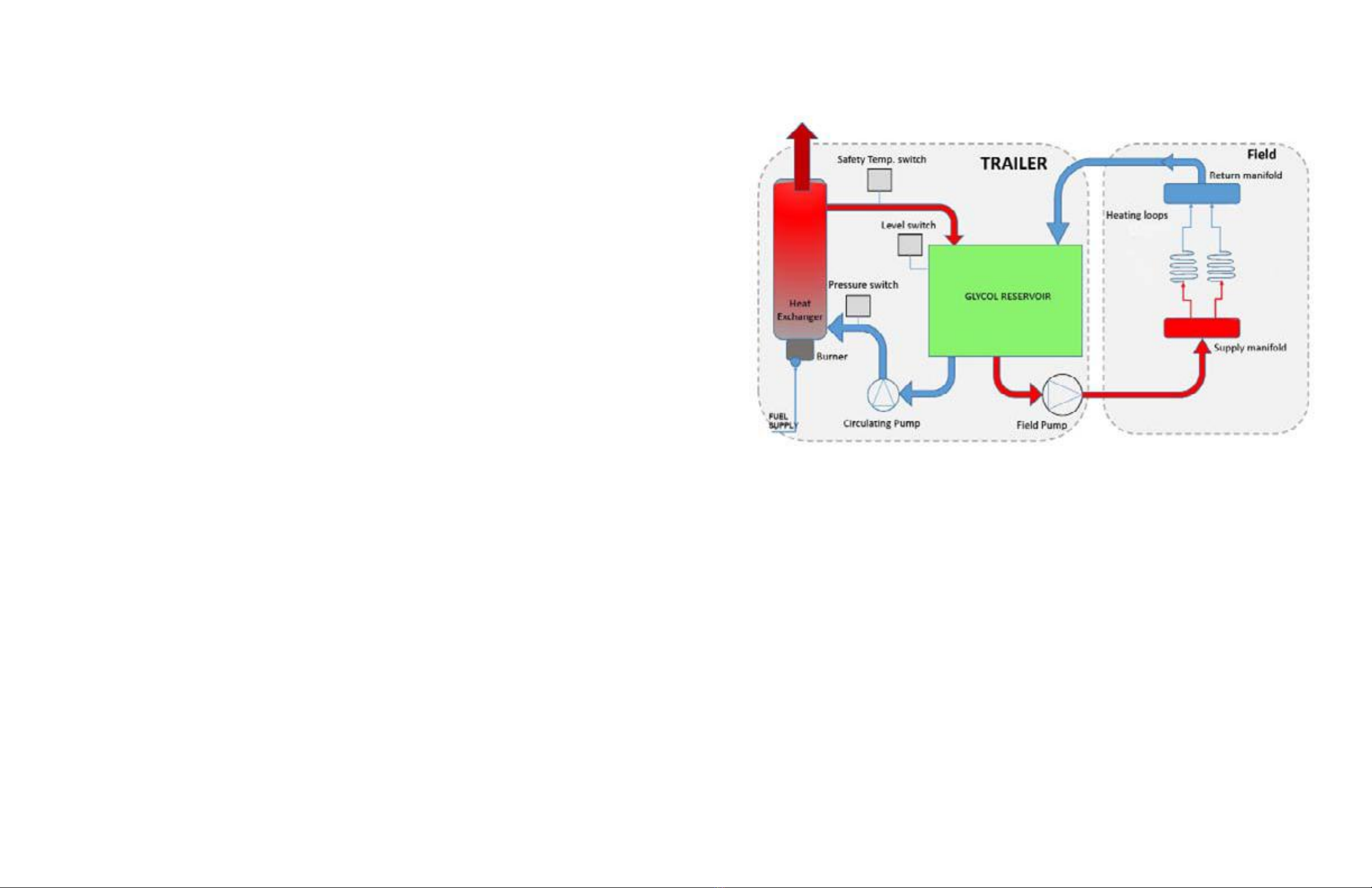
How It Works
The Heat King HK150 unit is designed to heat a propylene glycol water solution
which is then used for ground thawing, concrete curing or space heating. The glycol
solution is pumped out of its storage reservoir and heated in a high capacity heat
exchanger and returned to the reservoir until it reaches a user settable temperature.
The heat exchanger is a coiled pipe with a Diesel red burner. The reservoir is open
to atmosphere.
A eld pump draws the hot solution out of the reservoir and pumps it to the eld loop
for heating the area as required. There are supply and return manifolds on the back
of the unit. Heated solution is then pumped to the supply manifold, through the
hoses and back to the return manifold.The solution is then returned to the reservoir
for reheating. Controls panels hold the electronics and user controls.
HOW THE MACHINE WORKS
16 17

The HK150 is equipped with the following protective
devices to protect the user and the machine:
Emergency stop switch
The emergency stop switch is monitored by the controller inputs. The input is connected to
ground when the switch is pressed. In the event of an e-stop condition the system mode is set to
OFF and all output functions are shut down by the controller.
Pressure Switch
The pressure switch is designed to protect the burners and burner coils in the even of a pump
failure. The pressure switch is a normally open switch that closes when senses 12PSI from the
pump. If the switch does not sense pressure it wont allow power to go to the burners.
Low Water Cut O Switch
The low water cut o switch is in place to protect the burners and burner coils as well as the
circulating pumps in the unlikely event of loss of glycol. If the glycol goes down below the switch
level, the switch contacts will close and shut o power to the pumps and burners to avoid dam-
age.
High Limit Switch (aquastat)
The high limit switch is in place to be a backup to the other safety devices. It is an analog switch
that is set to 230°F, there is one on each coil. In the event that the burner coil was to heat up
past the user set point the High limit switch cuts the power to the burner to avoid overheating of
the coil.
Protective Devices Controls
A
C
B
E
D
F G
H I
J
KL M
N O
PQ
Before starting the unit , all operators should familiarize themselves
with the location and function of the controls.
18 19

A. Digital Display:
This system monitors the temperature of the
glycol in the reservoir and entering the circula-
tion manifold. It is shown on the digital display.
B. Return Temperature:
This gage monitors and displays the tempera-
ture of the glycol in the return manifold. It func-
tions only when the eld pump is running.
C. Total Operating Time:
This hour meter displays the total time that
power is provided to the heater loop.
D. Circuit Breaker:
Under normal operation, circuit breaker is de-
pressed. If circuit breaker load is exceeded, it
will trip the breaker and extend.
E. Ground Fault Interrupter:
This interrupter circuit monitors the power ow
through the system and trips or breaks the cir-
cuit when there is a ground or short. Correct
the condition, depress the red button to reset
interrupter and resume work.
F. Circuit Power:
This 2 position rotary switch controls the power
to circuit. Turn the switch clockwise to turn the
power to circuit on and counterclockwise for o.
The circuit power light will come on when the
power is turned on. The burner oil preheater
comes on to preheat the nozzle.
G. Hose Reel Direction:
This 2 position rotary switch selects the direc-
tion of hose reel operation. Turn the switch fully
clockwise to extend the hose and counterclock-
wise for retracting.
H. Hose Reel/Field Loop Selector Switch:
This 3 position rotary switch selects the system
that will be supplied with power. Turn fully coun-
terclockwise to select the hose reel system.
Move the switch to its vertical position to turn
o. Turn fully clockwise to provide power to the
eld loop system. In this position, the eld pump
light will come on.
I. Compressor/Heater Loop Selector Switch:
This 3 position rotary switch selects the system
that will be supplied with power. Turn fully coun-
terclockwise to select the (compressor system).
When this system is turned on, the compressor
light will come on. Move the switch to the vertical
position to turn o. Turn fully clockwise to turn
the heater loop circuit on. When this system is
turned on, the burner start-up sequence starts.
First, the circulation pump light comes on as
the pump starts. Then the burner igniter starts.
When that burner is operating, the burner ame
light comes on.
J. Emergency Stop:
This 2 position push-pull switch controls the
power to the machine. Push the switch in to stop
all machine functions and pull out to provide
power. It is recommended that all controls be
placed in their o position before the switch is
pulled out and power restored.
K. Circuit Power:
This light comes on when the power is turned on
and everything is functioning normally. It goes
out when the breaker or interrupter trips or the
power is turned o.
L. Circulation Pump:
This light comes on when the burner coil cir-
culation pump is on, and the pump is creating
pressure, and goes out when the pump is o.
M. Burner Flame:
This light comes on when the main burner is on.
The light goes out when the main ame goes
out.Light is not on when pilot is lit.
N. Field Pump:
This light comes on when the eld pump is
turned on and goes out when the pump is o.
O. Compressor:
This light comes on when there is power to the
compressor and goes out when the power is o.
Warning Indicators:
P. Low Glycol:
This left red light comes on when the glycol
reservoir level goes below the switch level
and goes o when the level is above. Stop
unit immediately and add glycol to the reser-
voir when this light comes on. Do not over
ll reservoir.
Q. Overtemp:
This right red light come on when the burners
are on with no call for heat.
Operating Temperature
Selection
The Heat King is designed with an
electronic programmable tempera-
ture controller. The temperature
controller will measure the tempera-
ture of the reservoir and will then
control the burner to maintain a set
temperature range. The unit comes
with a factory set operating tempera-
ture of 180°F with a 10°F (5.5°C)
temperature drop before the burner
will re again.
The operating temperature can be
set to operate at any temperature
up to 180°F (82°C) by following this
procedure:
a. Press 'SET' for 1 second. The set
value (desired temperature) will
then start ashing after a few mo-
ments.
b. Use the UP and DOWN buttons
on the right of the display to in-
crease or decrease the value.
c. Press 'SET' to conrm the select-
ed temperature press as the new
set point.
*The return temperature is only a
display and does not need to be
set.
SUPPLY TEMPERATURE CONTROLLER
20 21

Flashing Beacon
The Flashing Beacon is located on the rear of
the Heat King Unit. This beacon providesa visual
indication that the Heater Loop Circuit is in the "ON"
position.
Foot Pedal / Hose Reel:
The hose reel extend-retract function is controlled
by the foot pedal switch. Depress the pedal with
your foot to activate the reel drive and release it to
stop. Set the operating direction with the switch on
the control panel.Guide the hose with your hands
while the reel is turning. Always wear heavy gloves
to prevent burns.
Unspooling:
To spool out the hose, Loosen the belt tension knob
to allow the hose reel to free-wheel
out. Start pulling the hose o the reel, if you nd that
the reel is free-wheeling too fast, increase the drag
tension by turning the knob clockwise.
Spooling In:
To spool the hose onto the reel, turn the selector
switch on the control panel to the hose reel position.
Select “IN” on the hose reel direction switch. Adjust
the belt tension knob by turning clockwise. Depress
the foot switch to begin spooling in the hose. If you
nd the reel is not pulling the hose in and the belt is
slipping, increase the belt tension, with the belt ten-
sioning knob.Once the hose is all spooled in, tighten
the belt tension knob to lock the reel in position for
transport.
Valves:
Many circuits are designed with valves
that control the ow in the circuit.
Move the handle parallel to the line to
open the valve and at right angles to
close the valve. In most cases, a valve
is placed in a line to allow for conveni-
ent isolation and servicing of a system.
Valve ClosedValve Open
Fuel Fill Fuel Guage
Foot Switch
Belt Tension KNob
22 23

The machine must be placed and set-up
properly to perform as expected. Follow
these instructions when bringing the Heat
King to a work site and preparing it for opera-
tion.
1. Locate the unit in an area that is rm,
level and with good drainage to minimize
standing water. Be sure there is suf-
cient space on all sides to access the
machine as required.
2. Level the frame using the jack on the
hitch. Use a carpenters level to be sure.
3. Open all the doors and secure with the
anchor latch on the side of the frame
behind each door. Wait at least 10 min-
utes for the unit to vent and air out before
connecting power wires or starting unit to
allow the fumes and vapors to dissipate.
NOTE
If the frame is not level, the
burners will not be able to use
the total amount of fuel in the
tanks.
LEVELING
Set Up
FUEL FILL
4. Check the fuel level on the fuel gauge
under or beside the fuel lter or the
back of the fuel tank, add as required.
Do not smoke when refueling.
FIRE HAZARD
NO SMOKING
To prevent serious injury or death from
re:
• Do not smoke when refueling.
• Keep sparks, ames and hot material
away from ammable substances.
DANGER
201005
GLYCOL LEVEL
5. Check the glycol level in the reservoir.
Be sure the level is between minimum
and maximum levels.
6. Pull the Emergency Stop button out on
the control panel.
EMERGENCY STOP
HITCH JACK
24 25

Operating Procedure
Pre-Start checks & procedures
1. Level unit.
2. Ensure that all switches on the control panel are in the o position.
3. Plug plug-end into a dedicated 115 Volt, 60Hz, 20Amp circuits or optional onboard generator.
4. Check for adequate fuel level.
5. Check glycol level using sight gauge on the reservoir. Glycol level must be
above the minimum level and below the maximum level.
Start-up procedure
1. Turn “CIRCUIT POWER” switch on.
2. Set desired temperature on the temperature controller on the control panel.
3. Unlock the Hose Reel Locking Pin.
4. Turn the “REEL MOTOR/FIELD LOOP” switch to the “REEL MOTOR” position.
5. Turn the “HOSE REEL DIRECTION” switch to the “OUT” position, and using the
foot switch, uncoil the hose as required.
6. The hose reel can alternatively be used in the “Free Wheeling” mode without
the use of the foot switch.
7. Remove one length of hose at a time, plugging the quick connects in to the
corresponding quick disconnect on the manifolds.
8. Repeat step 7 with as many circuits as required.
9. Turn the “COMP/HEATER LOOP” switch to the “HEATER LOOP” position.
10. When the glycol resivoir reaches operating temperature, (small light in the
top left of the temperature controller screen stops ashing) turn the
“HOSE REEL/FIELD LOOP” switch to the “FIELD LOOP” position.
11. Inspect hoses to ensure they are not leaking, repeat after one hour.
Shut-Down procedure
1. Turn the “COMP/HEATER LOOP” switch on the control panel to
the “OFF” position.
2. Blow out eld hoses if required.
3. Turn the “REEL MOTOR/FIELD LOOP” switch on the control
panel to the “REEL MOTOR” position.
4. Turn the “HOSE REEL DIRECTION” switch to the “IN” position.
5. Depress the foot switch to begin reeling up the hose.
6. Reel in all hose circuits.
7. Turn all switches on the control panel to the “OFF” position.
Hose Blow-Out procedure
1. Close all supply manifold shut-o valves except for one.
2. Ensure that the air compressor shut-o valve is in the open position.
3. Turn the “COMP/HEATER LOOP” switch on the control panel to
the “COMP” position.
4. Wait approximately 5 minutes for the hose to blow out completely,
or untill a bubbling sound can be heard in the reservior.
5. Continue to blow-out the rest of the eld loop circuits one at a time.
6. Turn the compressor “ON/OFF” switch to the “OFF” position.
7. Turn the COMP/HEATER LOOP” switch on the control panel to
the “OFF” position.
Unwinding Hose and Connecting to Manifold
IMPORTANT: Before proceeding with the following steps, verify emergency stop button is pulled out and
system power is “ON”.
1. Remove the foot control pedal from storage location, Place on a piece of plywood on the ground to
keep it dry.
2. Select “OUT” on the hose reel switch.
ALWAYS wear gloves when handling the heat transfer hoses.
3. Depress the foot control pedal to begin unwinding the first loop of hose, guiding it off of the hose reel
until approximately 12 ft. (3.65m) of hose has been run off the reel. Remove foot pressure on the foot
control pedal.
NOTE: The operator also has the option to manually unwind, or “freewheel”. Use the belt tensioner knob to
free wheel.
4. Connect the hose coupler to the corresponding hose coupler of the supply manifold. Start with the
rightmost coupler on manifold.
5. Depress the foot control pedal and begin unwinding the remaining loop of hose and place for concrete
curing or thawing.
6. Connect the opposite end of each hose to the corresponding coupler of the return manifolds.
Repeat these steps when adding more loops, connecting the following hose to the next coupler of supply
manifold in sequential order. Connect the opposite end of each hose to the corresponding coupler of the return
manifolds.
ATTENTION: For optimal efficiency, use only one hose (700ft.) per loop. Two or more hoses will reduce flow
rate of heat transfer fluid.
Return foot control pedal to storage location when finished.
Hose layout Guideline
26 27

MAINTENANCE SAFETY
FLUIDS AND LUBRICANTS
1. Grease:
Use SAE multipurpose high temperature
grease or a multipurpose lithium base grease.
2. Fuel:
#1 or #2 Diesel Fuel
3. Glycol:
Use only Tamarack glycol for all operating con-
ditions. Polypropylene 50% glycol 50% water.
Do not mix or combine other types.
Hk300 reservoir Capacity: 96 gallon.
Hk500 reservoir Capacity: 130 gallon.
4. Gearbox Oil:
Use an SAE 80W90 oil for all operating condi-
tions. Do not mix oil types or viscosities.
Gearbox Capacity: 1.5 US qts.
5. Storing Lubricants and Fluids:
Your machine can operate at top eciency only
if clean lubricants are used. Use clean contain-
ers to handle all uids. Store them in an area
protected from dust, moisture and other con-
taminants.
GREASING
Use the Maintenance Checklist provided to keep a
record of all scheduled maintenance.
1. Use only a hand-held grease gun for all greas-
ing. An air-powered greasing system can
damage the seals on bearings and lead to early
failures.
2. Wipe grease tting with a clean cloth before
greasing to avoid injecting dirt and grit.
3. Replace and repair broken ttings immediately.
4. If ttings will not take grease, remove and clean
thoroughly. Also clean lubricant passage. Re-
place tting if necessary.
1. Review the Operator's Manual and all safety
items before working with, maintaining or
operating the Heater.
2. Place all controls in their OFF position, dis-
connect power cords and wait for all moving
parts to stop before servicing, adjusting or
maintaining.
3. Have a rst-aid kit available for use should the
need arise and know how to use it.
- Keep service area clean and dry.
- Be sure electrical outlets and tools are
properly grounded.
- Use adequate light for the job at hand.
4. Keep hands, feet, clothing and hair away from
all moving and/or rotating parts of the hose
reel and drive system.
5. Always wear heavy gloves to prevent burns
when handling hot components. Wait until burn-
ers, coils and glycol system components have
cooled before working on them.
6. Do not attempt any adjustment or maintenance
to any system of the Heater unless the power
wires are disconnected.
7. Make sure that all guards, shields and hoods
are properly installed and secured before oper-
ating the Heater.
8. Securely support the machine using blocks
or safety stands before working beneath it or
changing tires.
9. Store and transfer diesel fuel, solvents, cleaners
or any ammable liquids only in safety standard
approved containers.
Maintenance Chart
Description Operation Every
750
Hours
Monthly Annually
Burner Nozzle Change X
Burner Electrodes Change X
Burner Fuel lter Change X
Glycol Filter Clean X
Grease Axle Hubs Service X
Grease Reel Bear-
ings
Service X
Reel Gear Box Check X
2928

3130
Maintenance-Burners
CHANGING FUEL NOZZLES
AND ELECTRODES
Annually or every 750 hours (or more often if fuel
quality is poor) the fuel nozzels and elecrodes
should be changed. To change, follow this proce-
dure:
1. Remove the drawer assembly (fuel tube, ame
turbulator, fuel nozzle, electrodes) from the
burner chasis. .
2. Loosen the set screws that hold the electrode in
place and remove them. Note there is a left and
a right side electrode.
3. Remove the nozzle with a standard wrench and
also use a backup wrench to keep the drawer
assembly base from turning.
4. Replace the nozzle with the appropriate size for
your Heat King model.
NOTE: use semi solid or hollow cone spray pat-
tern nozzels.
The HK 150 uses a 1.0 GPH 80° A nozzle @ 120
psi
NOTE : FOR HIGH ALTITUDE USE (4000+ ft above
sea level). Use the appropriate size for your
model.
5. Make sure nozzle is tight and then install the
electrodes, set the gap and hieght according to
this diagram, diagram 1 or use the appropriate
wayne burner gap gauge.
DO NOT TAMPER WITH THE UNIT OR
CONTROLS - CALL YOUR SERVICE PER-
SONNEL.
To ensure continued reliable operation, a
qualied
service technician must service this burner
every 750 hours.
More frequent service intervals may be re-
quired in
dusty or adverse environments.
Operation and adjustment of the burner re-
quires
technical training and skillful use of combus-
tion test
instruments and other test equipment.
How to remove burner drawer
assembly step #1
1. Remove brass fuel tting with a 7/16” wrench
2. Remove lock nut with a 9/16” wrench.
3. Take note of where the depth guage is set at, mark a line if necessary.
4. Loosten depth guage lock screw with a at screw driver or 5/16” nut driver.

33
32
How to remove burner drawer
assembly step #2
1. Loosen transformer lock screw with a at screwdriver or 5/16” wrench
2. Remove transformer screws with a ast head screw driver or 1/4” nut driver
How to remove burner drawer
assembly step #3

Fuel Filter:
The burner fuel circuit is designed with a lter to remove contaminants and water
from the fuel. Change lter every 750 burner hours to keep the system clean.
Change more frequently if contaminants are introduced into the system during re-
fuelling. In the bottom of each of the lter is a knob that can be loosened to drain
water out that gathers in the bottom of the lter.
Note: Put a pan under the fuel lter when changing them, to capture any fuel that
may leak or drip. Dispose all fuel related items responsibly.
Filters
3534
Replacing the nozzle and
electrodes
1. Remove the nozzle with a 5/8” and 3/4” wrench and replace with a new nozzle.
2. Move by loosening the electrode screws and sliding electrodes up or down.
3. Make ne electrode adjustments by bending the electrodes.
4. After replacing the nozzle and electrodes reinstall the drawer assembly oppo-
site the way you removed it.
5. Set the drawer depth back to the the mark where it was originally set.

Glycol Strainer:
The glycol circuit is designed with a strainer in the eld loop circuit to re-
move all contaminants from the system. Clean the lter every year to keep
the system clean. Clean more frequently if dirt gets in during lling or hose
attaching.
Note: To clean lter rst you will have to separate the union and then you can
thread the strainer out of the glycol tank. To clean the strainer ush out with wa-
ter until any debris is rinsed out.
Right
Left
SERVICING INTERVALS
Daily or 8 Hours
1. Check glycol reservoir level. Top up as
required.
GLYCOL LEVEL
Each Heating Season
3. Grease the reel bearings (2 locations).
2. Check the oil level in the gearbox
(view shown is system removed from
machine).
GEARBOX OIL LEVEL
3736

Service Parts
Item Part #
Burner
1.0 80° A GPH Nozzle 449053
LHS Electrode 449030
RHS Electrode 449003
Cad cell 446491
Transformer 449014
Primary Control 446490
Fuel lter 445157
Circulation Pump 1/2 HP
Mechanical Seal Kit 449059
Gasket 449012
Field Pump 1/2 HP
Mechanical Seal Kit 449059
Gasket 449012
Troubleshooting
The Tamarack Construction Heat King is a self-contained glycol heating system that can be used to thaw
frozen ground or maintain a work area at a constant temperature. It is a simple system that requires minimal
maintenance.
In the following trouble shooting section, we have listed many of the problems, causes and solutions to the
problems which you may encounter.
If you encounter a problem that is dicult to solve, even after having read through this trouble shooting sec-
tion, please contact your authorized dealer, distributor or the factory. Before you call, please have this Opera-
tor’s Manual and the serial number from your machine ready.
PROBLEM CAUSE SOLUTION
Burners won’t start. No fuel. Fill the fuel tank.
No power. Plug machine in and turn on.
Breaker tripped. Reset breaker.
Low glycol. Fill glycol reservoir.
Switch o. Pull out Emergency Stop switch.
NOTE: For the burners to be able to re, three conditions must be met.
1) The Pressure switch on the circulation loop must see pressure. (gray plastic box on circ pump)
2) The low glycol sensor must sense glycol. (blue box on glycol tank)
3) The aquastat temperature has to allow the call for heat, by being below 230°F. This condition
would be very rare, and should only trip o if there is not enough ow through the coil or the burner is burning
too hot. (gray box on coil discharge beside exhaust)
Buners give o black smoke. Wrong fuel/air mixture. Reset air mixture.
Fouled burner. Clean burners.
Plugged fuel lter(s). Change lter(s).
Reel won't move. No power. Turn power on.
Reset circuit breaker.
3938
Table of contents
Popular Burner manuals by other brands

Weber
Weber Genesis 2000 Accessory installation guide

Ecoflam
Ecoflam MAX 15 operating instructions

Riello
Riello Gulliver BS2D Installation, use and maintenance instructions

Hansa-electronic
Hansa-electronic HMG operating manual

baltur
baltur BT 75 DSPG Maintenance, use and installation manual

Unigas
Unigas HP60 manual

Riello
Riello RL 70/M Installation, use and maintenance instructions

Riello Burners
Riello Burners RL 70/2 Installation, use and maintenance instructions

Riello
Riello RG0.R One stage operation

Ecoflam
Ecoflam MAX P 45 AB manual

King Kooker
King Kooker 80BP Assembly instructions and use and care manual

Riello
Riello 466 M1 Installation, use and maintenance instructions