GENERAL PRODUCT INFORMATION
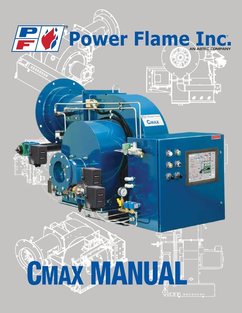
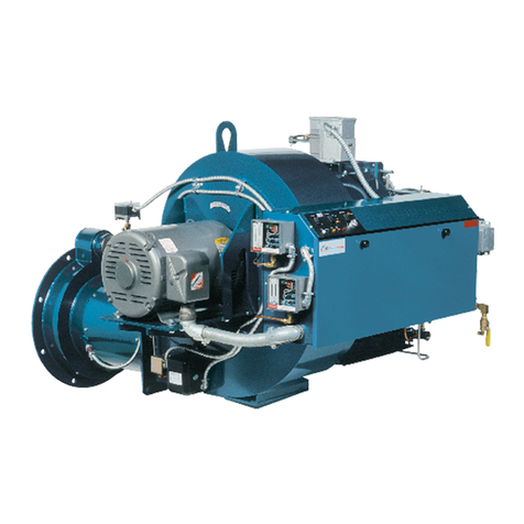
Power Flame Model HAC and HACR (inverted) burners incorporate the principles of air atomization for all fuel oils,
and multiple-orifice, high velocityvortex mix operation for gas. The total package utilizes the forced-draft, flame-
retention concept. All air forcombustion iscompletelyfurnished bythe burner fan. The burnercan be operated under
positive or negative furnace pressures with clean efficient combustion of fuels. Forced draftpressurized operation
permitsstacks of smaller diameter and height. The oil pressure required for airatomization variesfrom20 to 70 psig.
Oil flowis controlled bya metering valve in the nozzle supplyline.
The Power Flameair-atomizing burner consists ofatotallypackaged and tested system(with unit responsibility)
capable ofdelivering to the combustion area properlyatomized fuel with aspraypattern to match the air pattern.
Accurate control of atomized fueland air results in properflamepatternsandcleancombustion formaximumefficiency
throughout the firing range. A proven gas pilot ignites the main fuel.
An electric trimheater is supplied as an integral partofthe burner assemblywhen supplied for #4 or heavier grades
offuel oil.On burners for#4, #5and#6gradefueloil,oilfroma continuouslyoperatingoilpump ispumpedthrough
an auxiliaryheater(steamofhot watermaybe the auxiliaryheating medium)underaccurate temperature control then
through a thermostaticallycontrolled electric heater. Theseauxiliaryheaters arenota partofthe standardHACburner
package.
The electrictrimheaterisprimarilyfortrimheating and maybe used forcold starting. The thermostat isset at a value
slightlyhigherthan thatofthe steamorhot waterheater. The auxiliaryheatertakes overafterthe steamor hot water
isgenerated and maintainsconstant temperature ofthe oilto theburner, to provide viscositycontrol, which isessential
to good atomization.
Theoil pumpsupplies oilto thesysteminexcess of burnerrequirements. Anoil-regulating valvemaintains relatively
constant oil supplypressure. The oil in excess ofburner firing requirements is returned to the storage tank.
Frequently,on multiple burner installations asingle, separate, remote pumpand heater set is used to preheat and
transfer the fuel to the burner assemblies. These pump and heater sets are not apart of the standard HAC burner
package.
A matchedandpretestedair compressor,drivenbyaseparatemotor,suppliestheairforatomizationandpurgingof
the oil line and nozzle at the end ofeach firing cycle (#4, #5 and #6 oil only). The compressor is equipped with a
pressure reliefvalve, intakefilter and air receiver tank.An orifice bleed valve permits selection ofthe proper air
pressure to suit various grade offuel oil.
On anormal limit shutdown, the safetyoil valve is de-energized and oil flowto the nozzle is interrupted. On #4, #5
and #6 oil the air purge valve is energized to permit compressor air to flowthrough the burner piping and nozzle,
leaving it clean for next firing cycle.
Combustionair isprovidedbyaforwardcurvedbladefan,drivenbyan integralmotor,and controlledbyadual blade
inlet damper operated bya modulating motor actuator.
The modulating motor provides modulated positioning ofthe oil metering valve, the gas metering valve (on gas-oil
burners only)and the dual blade inlet air damper throughout the firing range. It is controlled byapressure or
temperature activated potentiometric control thatmatchesfiring rate with load demand.The fuel-airratio is established
at the timeofstart up bylinkage adjustment and set with combustion test equipment to provide the highestpractical
CO2with a clean flame.
A flamesafeguard programmer,availableinnumerouscontrol sequences,programs thefiring cycles fromprepurge
through post purge. Thecycle is sequenced to provide normal and safe conditions before fuel can beintroduced into
the combustion area. The complete firing cycle is supervised. Ignition and main flame failure protection is fast and
reliable to render the burner inoperable in the event ofpilot for main flame failure and to provide an alarmsignal.
-1-


