Heat Seal 700ES Guide
Revised 2018
READ ALL INSTRUCTIONS CAREFULLY BEFORE OPERATING EQUIPMENT
OPERATING & SERVICE PARTS MANUAL
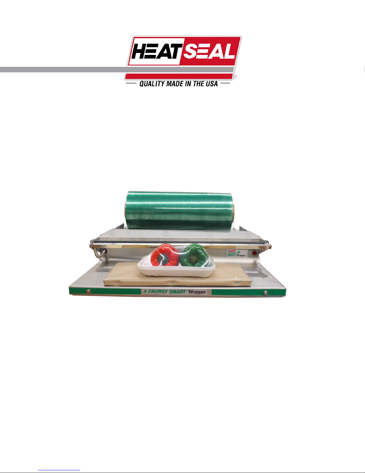
700ES ENERGY SMART WRAPPER
SERIES C
2
Revised 2018
TABLE OF CONTENTS
Machine Components & Electrical Requirement ........................................................3
Preliminary Setup..........................................................................................................5
Recommended Maintenance ........................................................................................6
Troubleshooting Guide .................................................................................................7
Heater Control Board Assembly...................................................................................9
Service Parts Information ...........................................................................................10
3
Revised 2018
MACHINE TECHNOLOGY & COMPONENTS
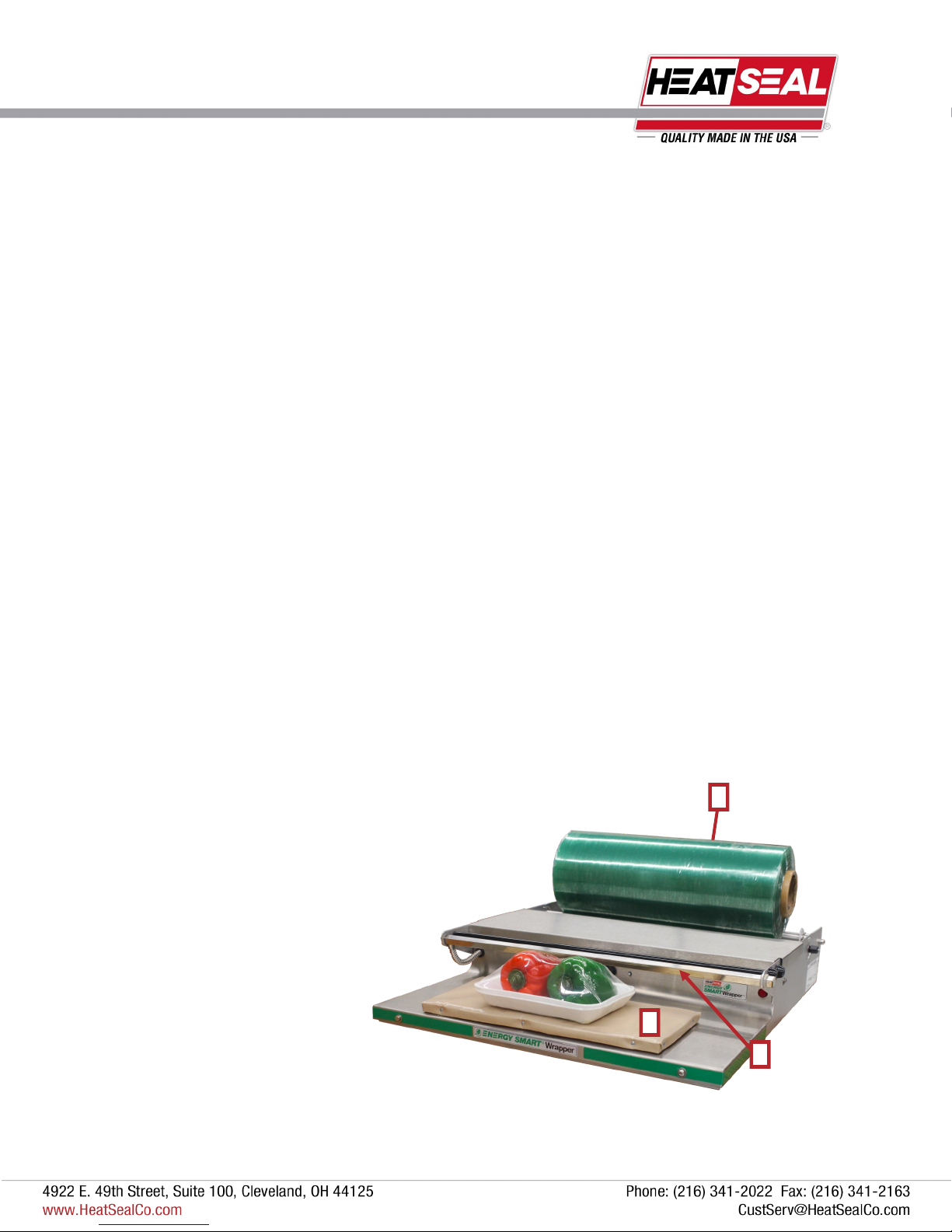
HOT ROD HEAT UP
With the film properly mounted and threaded, the wrapper is ready to be powered up.
After plugging in the power cord, toggle the power switch (1) located on the back of the electrical box to the ON position.
The hot rod (2) will require approximately 12 minutes to warm up before it reaches cutting temperature.
CAUTION: When the wrapper is on the rod will remain hot at all times.
PHOTOEYE ACTUATED HEATER
The seal plate of the wrapper (3) cycles on when the photoeye is triggered. Triggering the photoeye occurs when a pack-
age is place on the seal plate.
This feature ensures that the seal plate will consume energy only when there is a demand by the operator.
ENERGY SMART® TECHNOLOGY
The Energy Smart® Wrapper is an innovative system that incorporates an “Instant On” seal plate with the ability to go
from ambient to sealing temperature. The high speed seal plate, in combination with a photoeye actuator, allows the
operator to seal a product on demand and to save energy when the wrapper is not in use.
As a part of our quality procedures, the seal plate has been tested. Note: You may see a wavy or wrinkling affect on
the surface of the stainless steel plate under the replaceable non-stick cover; it is normal. This waviness is caused
by the thermal expansion of the materials that are used to construct the seal plate; wrinkling will be observed over time.
Due to the advancement of this new technology, it is important to maintain the non-stick cover in good condition. It is
recommended to replace the cover at least once every three months to protect the seal plate and maintain a sanitary
surface.
1
3
ELECTRICAL
REQUIREMENT
The Model 700ES requires 115 volts,
15A Circuit.
2
4
Revised 2018
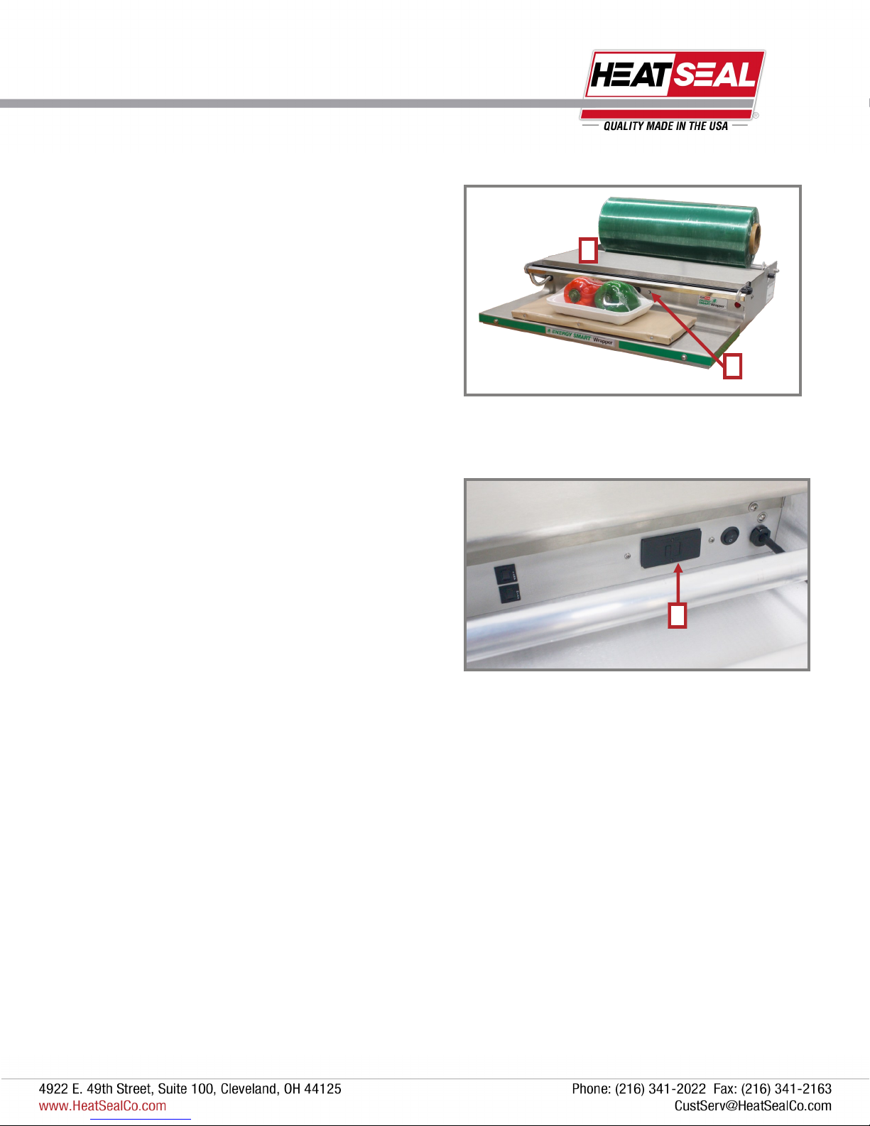
STAINLESS STEEL BRIDGE
The stainless steel bridge is not recommended as a cutting
surface and should not be used as one.
INDICATOR LIGHT
The LED light near the center of the unit (2) illuminates to indi-
cate that the heat cycle is in process. The light will turn yellow
while the plate is heating and then red when the plate reaches
sealing temperature.
GFCI
The GFCI (3) is located on the rear surface of the unit. The
GFCI may need to be reset if the wrapper gets wet or other
ground faults arise. Do not reset the GFCI, if visible seal
plate damage is present.
1
2
3
MACHINE TECHNOLOGY & COMPONENTS
THERMISTOR TEMPERATURE CONTROL
Due to the rapid response of the seal plate and residual heat that can remain from previous cycles, a thermistor is
incorporated as a temperature control device. The seal cycle can be shorter than 3 seconds when residual heat is present in
the seal plate. The thermistor, located within the seal plate, regulates the temperature of the seal plate to ensure that the
temperature peaks at 350˚F.
5
Revised 2018
PRELIMINARY SETUP
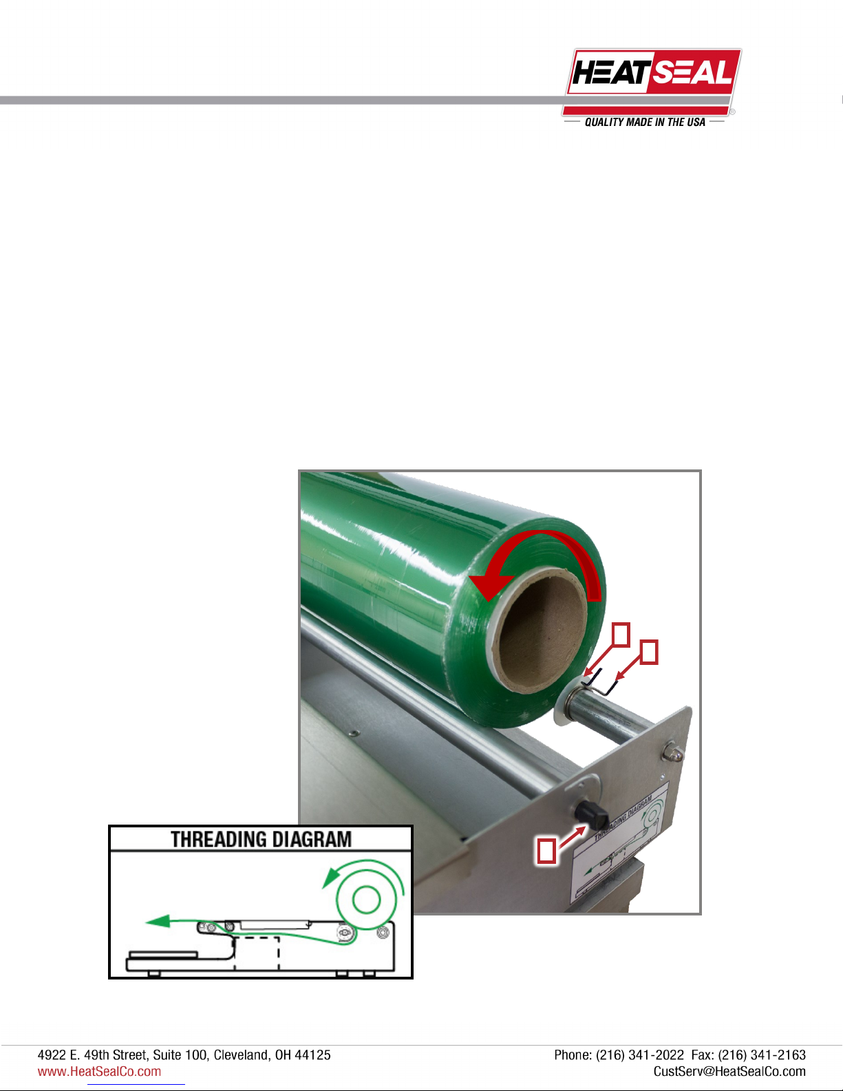
FILM THREADING
Film threading is important to achieve proper film tensioning. Proper film tensioning allows for the easiest cutting of film.
Facing the tension knob (1) side of the machine, the film should come off the roll counter-clockwise and route down and
between the two rollers. The film goes under the wrapping bridge and rests on top of the black retainer rod.
The black tension knob can be adjusted for loose (rotate counter clockwise) or tight (rotate clockwise) tension on the film.
A threading diagram is located on each unit under the tension knob.
ADJUSTING FOR DIFFERENT WIDTH FILMS
Slide the white film guides (2) and squeeze the tensioning clips (3) (one on each side of film roll) to center it.
3
1
2

6
Revised 2018
RECOMMENDED MAINTENANCE
MAKE SURE TO TURN OFF THE UNIT, UNPLUG
AND LET THE MACHINE COOL DOWN BEFORE CLEANING *
NON-STICK COVER & SEAL PLATE
The seal plate can be cleaned, as needed, with a mild spray degreaser. This should be applied to a soft cloth or paper towel
and then wiped on the plate while cold. DO NOT WASH DOWN SEAL PLATE OR SPRAY ANY LIQUIDS DIRECTLY
ONTO THE PLATE.
Replace covers as needed (approximately every 3 months).
CUT OFF ROD
①Make sure that the unit is turned off and the cut off rod is cool to the touch.
②Cover the unit with paper towels to protect it from over spray and debris.
③ Spray the cut-off rod generously with an FDA approved “Degreaser.”
After soaking for a few minutes, lightly scrub the surface of the Cut-off rod with a nylon based product (Scotch-Brite™).
Wipe the surface clean of debris and residue with clean paper towels or cloths and repeat as needed.
CLEANING THE UNIT
The 700ES can be wiped down using mild cleaning detergent and a soft cloth or paper towels. DO NOT HOSE DOWN OR
SUBMERSE THE UNIT.
7
Revised 2018
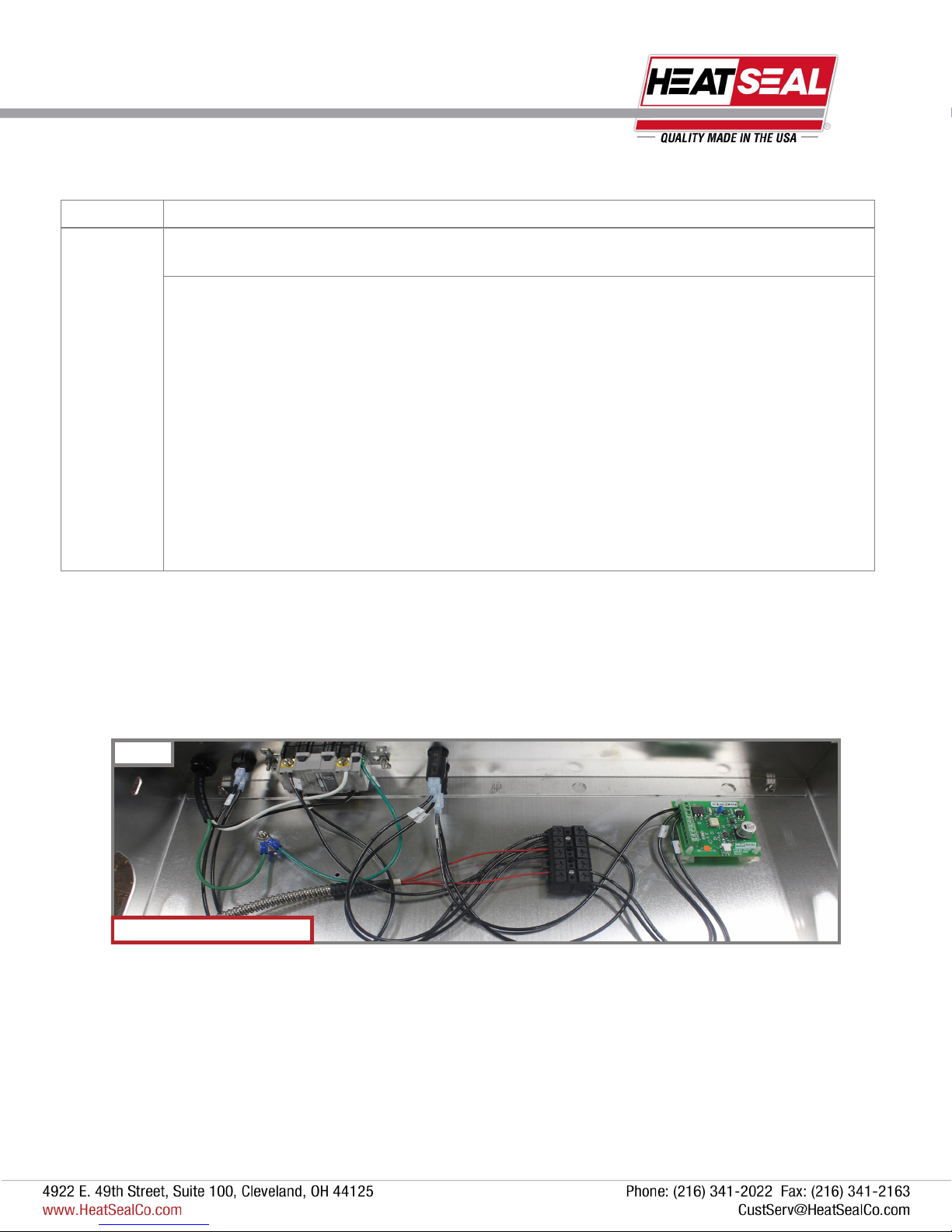
TROUBLESHOOTING
700ES Electrical Box Pictured
Figure 1
Symptom Possible Solution
No power to
the unit.
Verify the unit is plugged into a 15 Amp circuit, and the Power Switch is set to the “ON” position.
Is the GFCI circuit breaker tripped?
1) Remove “Non-Stick” Cover and inspect the Seal Plate for the following defects:
Punctures or cuts.
Burn marks.
Discoloration.
If these defects are present, replace seal plate.
2) If seal plate is in good condition, reset GFCI. If GFCI cannot be reset, replace, GFCI.
3) Reset new GFCI. Red Power Light at right front of unit SHOULD glow.
4) If GFCI trips, seal plate may have moisture inside. Allow 1-2 days to dry out and then retry.

8
Revised 2018
TROUBLESHOOTING
Symptom Possible Solution
Unit has power
but the Seal Plate
does not work
Verify power. Does the LED light turn ON when photo eye is triggered?
1) If neither the LED or Seal Plate work, verify that the 20 Amp Circuit Breaker has not
tripped.
2) If the Circuit Breaker has tripped, verify there are no shorts to ground in the unit by
checking wiring and connections (on page 1). Reset Circuit Breaker.
3) Replace Circuit Breaker if it cannot be reset.
Verify the Photo eye is working properly.
1) With the Power ON, there should be a Green Light illuminated on the back of the
Photo Eye. When the Photoeye is triggered a separate Yellow Light will illuminate.
2) If the green light is ON and the yellow light does NOT illuminate when the Photo
Eye is triggered, replace the Photo Eye.
3) If green light is NOT illuminated when power is ON, check Control Board to
determine if Photo Eye or Control Board is faulty.
Verify the control board is working.
1) Check the voltage on Pin 1 of the Control Board using a multimeter. If it is not
120vac, a wiring issue exists. Find and repair.
2) Check voltage across Pin 4 & 5, (Brown & Blue Wires) this voltage should be 10 to
30vdc.
If NO voltage present, replace Control Board.
If voltage present, replace Photo Eye.
Verify seal plate. If the plate does not heat at all or is only slightly warm to the touch,
replace the Seal Plate.
Film Cut-off Rod
does not work at
all.
Verify the unit is plugged into a 15 Amp circuit and the Power Switch is set to the “ON”
position.
Verify that the 1 Amp circuit breaker is not tripped. If the circuit breaker is tripped, then reset
and verify there are no shorts to ground in the unit by checking wiring and connections.
Film cuts too
slowly
Clean Cut-off Rod surface and verify it is not bent. See “Cut-Off Rod” Maintenance.

9
Revised 2018
HEATER CONTROL BOARD ASSEMBLY
NEUTRAL
HEATER OUT
24V
0V
AUX
PRODUCT DETECTION
(+) THERMISTOR
(-) THERMISTOR
120 VAC

10
Revised 2018
SERVICE PARTS INFORMATION
5
1
2
3
BILL OF MATERIALS FOR MAJOR SUB-ASSEMBLIES
ITEM QTY PART NUMBER DESCRIPTION
1 1 5901-011 Non-stick Cover, 6 x 15
2 1 6137-149 Replacement 6 x 15 Seal Plate Kit
3 1 6137-094 Hot Rod Replacement Kit Includes: (1) Square Cutoff Rod,
(1) Rubber Grommet, (1) Size 206 O-Ring
4 1 6340-064 Vinyl Replacement Kit Includes: (1) Film Retainer, (2) Black Plastic Shaft Retainer
5 1 6340-066 Bridge Replacement Kit Includes: (1) Stainless Steel Wrapping Bridge, (1) Stainless Steel
Rod, (2) Black Plastic Retainer
6 1 6341-009 Stainless Steel Rod
7 1 6340-063 Replacement Cap Kit Includes: (2) Black Plastic Shaft Retainer
8 Electrical Box Assembly (See Page 12)
9 1 6341-029 Tensioning Roller Kit
10 1 2145-052 Tensioning Knob
11 1 6341-031 Idle Roller Kit
12 1 6341-032 Film Centering Device Kit
13 1 1872-133 Photo Eye
6
4
9
11
7
12
8
10
13
11
Revised 2018
1
2
3
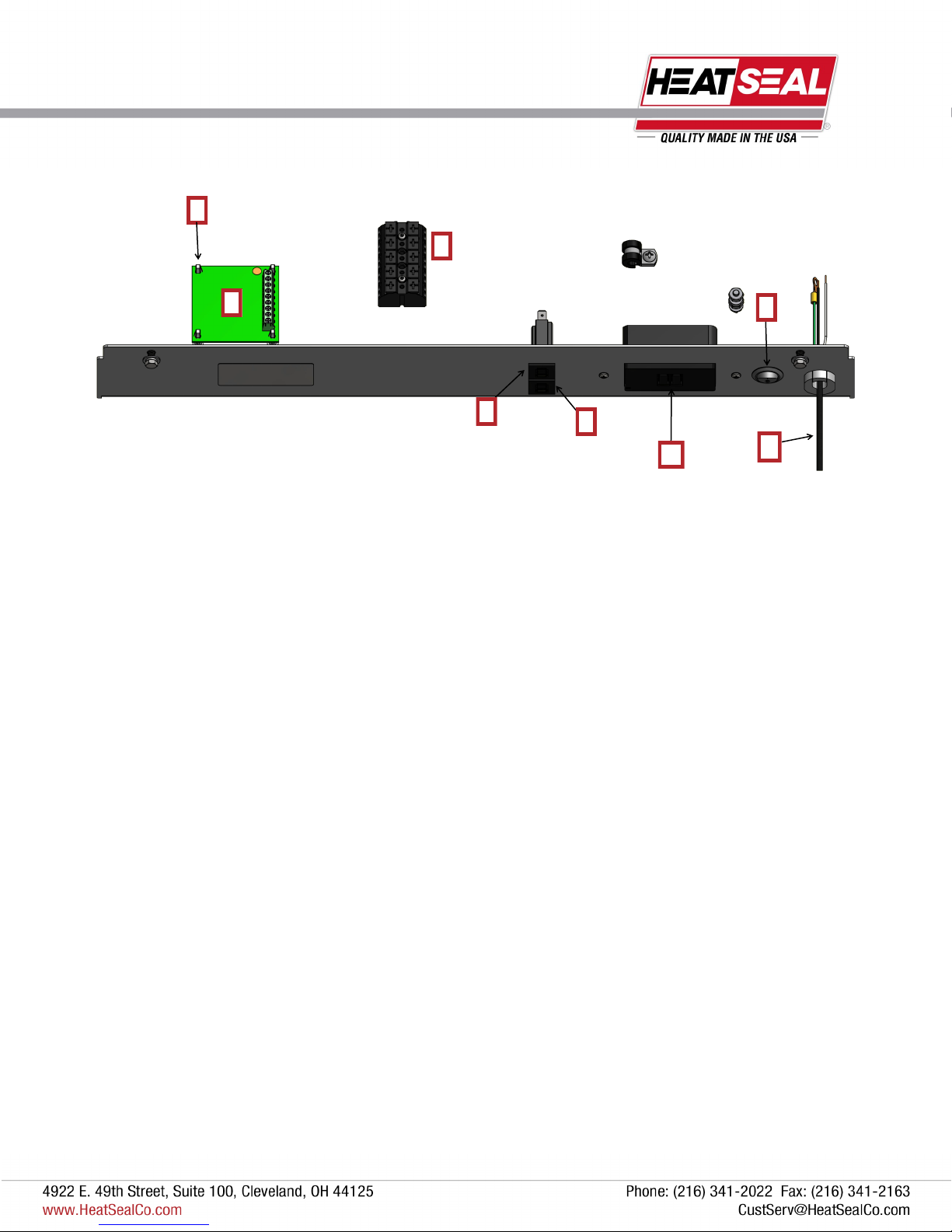
BILL OF MATERIALS FOR ELECTRICAL BOX
ITEM QTY PART NUMBER DESCRIPTION
1 1 1818-035 Circuit Board Assembly, Energy Smart Wrappers
2 1 6340-070 Circuit Board Mounting Kit Includes: (4) Plastic Clip Stand-Offs
3 1 1875-055 Terminal Block
4 1 1815-030 1A Circuit Breaker
5 1 1815-031 20A Circuit Breaker
6 1 1872-123 GFCI Blank Outlet, 20A/125V
7 1 1872-131 20A Rocker Switch
8 1 6340-069 Power Cord Replacement Kit Includes: (1) Strain Relief, (1) 7’ Power Cord
ELECTRICAL BOX & HOT PLATE PARTS
7
4
6 8
5
Other manuals for 700ES
1
This manual suits for next models
1
Table of contents
Other Heat Seal Stretch Wrapping System manuals


