Heat Seal 200ES Guide
Revised 2019
READ ALL INSTRUCTIONS CAREFULLY BEFORE OPERATING EQUIPMENT
OPERATING & SERVICE PARTS MANUAL
200ES ENERGY SMART WRAPPER
200ES-C6AXXXB
*pictured with optional Paper Cutter
Certified

2
Revised 2019
TABLE OF CONTENTS
Machine Components & Electrical Requirements ......................................................3
Preliminary Setup..........................................................................................................5
Cradle Mount Film Setup
Recommended Maintenance ........................................................................................6
Guide For Optional Paper Cutter..................................................................................7
Troubleshooting Guide .................................................................................................8
Control Board Assembly.............................................................................................10
Service Parts Information ...........................................................................................12
Major Assemblies
Electrical Box Components

3
Revised 2019
MACHINE TECHNOLOGY & COMPONENTS
HOT ROD HEAT UP
First, place the desired film in cradle mounts and thread the film up through the machine according to the diagram on the
right side of the unit.
Plug in the power cord. There is a switch on the right side of the electrical box that you may turn on.
Turning on the unit will allow the film cutting rod (1) to begin to heat, it will take a few minutes to get up to optimal cutting
temperature.
Caution: The film cutting rod will continue to heat while the wrapper is turned on, so contact by any objects other than the
film should be avoided.
PHOTOEYE ACTUATED HEATER
The heat cycle in the seal plate (2) begins when a package is placed in front of the photo-eye on the seal plate.
This feature ensures that the seal plate will consume energy only when there is a demand by an operator.
Do NOT use the seal plate as a cutting surface, this will damage the heating foil and non-stick cover. Seal plate damage
voids the warranty.
ENERGY SMART TECHNOLOGY
The Energy Smart Wrapper is an innovative system that incorporates an “Instant On” seal plate with the ability to go from
ambient, to sealing temperature in seconds. The wrapper uses a photo eye to see when a store associate is wrapping a
package and initiates a heat cycle (approximately 3 seconds). After the cycle, the wrapper stops heating to conserve
energy.
Heat Seal tests all seal plates before they ship. Thermal expansion in the seal plate layers will create a wrinkle effect –this
is normal.
1
2
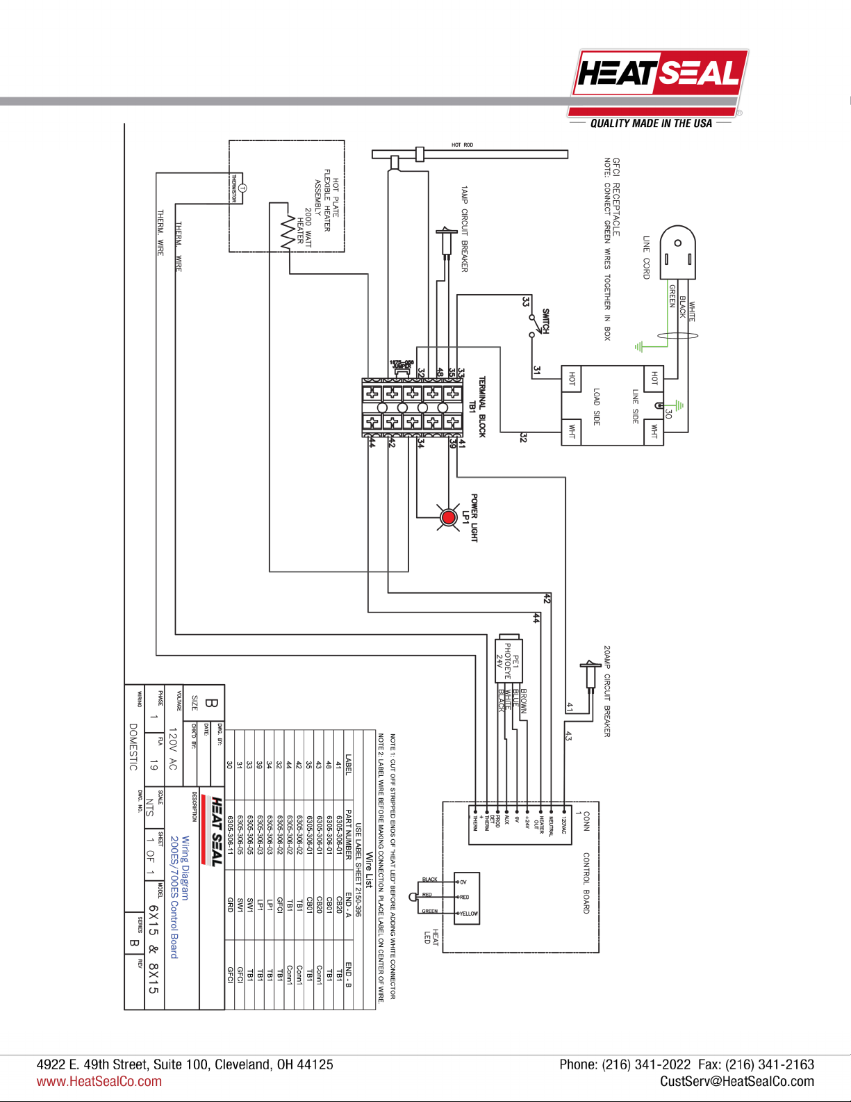
ELECTRICAL
REQUIREMENTS
The Model 200ES requires 120 volts, 60Hz, 132 watts
*200ES pictured with optional Paper Cutter

4
Revised 2019
MACHINE TECHNOLOGY & COMPONENTS
THERMISTOR TEMPERATURE CONTROL
Due to the rapid response of the seal plate and residual heat that can remain from previous cycles, a thermistor is
incorporated as a temperature control device. The heat cycle can be shorter than 3 seconds when residual heat is present in
the seal plate. The thermistor is located inside of the seal plate assembly.
STAINLESS STEEL BRIDGE
The wrapper comes with a stainless steel bridge (1) that can
be utilized as a working surface while preparing products.
The stainless steel bridge is not recommended as a cutting
surface.
TWO ROLL CAPACITY
The wrapper can hold two 20” rolls of film (2). The rolls should
be mounted and threaded as shown on page 5. There is also
a threading diagram located on the right side of the unit.
OPERATOR INDICATOR LIGHT
A dual-colored light (3) will change from yellow, when the
plate is heating, to red when the plate is at film sealing
temperature.
GFCI
To maintain circuit protection and integrity, a GFCI (4) is
installed in the electrical box, and may need to be reset if
wrapper gets wet or other ground faults arise. Do NOT
reset the GFCI, if visible seal plate damage is present.
4
*200ES pictured with optional Paper Cutter
5
Revised 2019
PRELIMINARY SETUP - CRADLE MOUNT
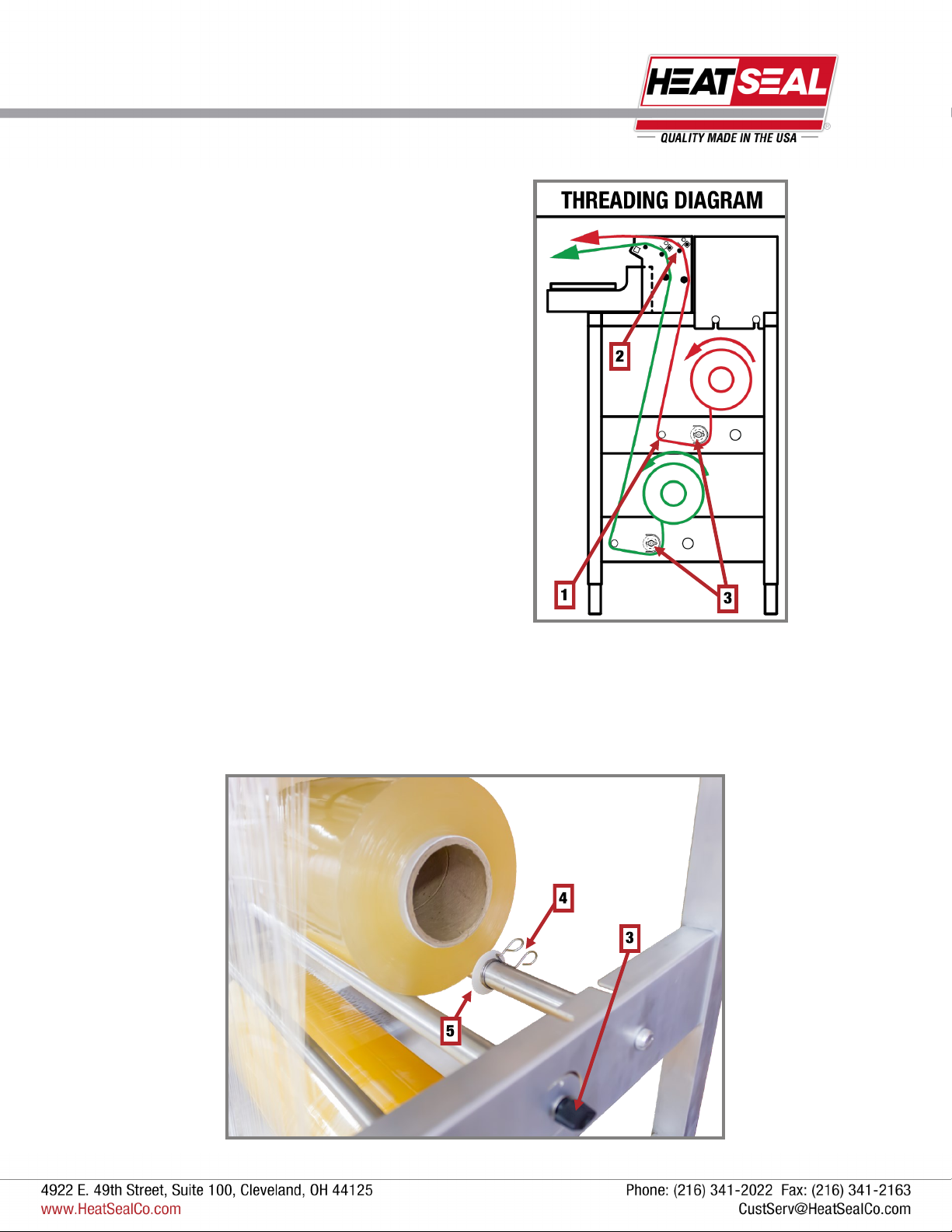
FILM THREADING - CRADLE MOUNT
There is a film threading diagram located on the right side of
the unit.
Film threading is very important to achieve proper film tension.
Route the bottom film first.
Facing the tension knob side of the machine, the film should
come off the roll counter-clockwise and go in-between the two
rollers it sits on.
Pull film under the film guide roller (1), and up through the film
selector rollers, starting with the nearest slot to the hot plate
first (2).
The black tension knobs (3) can be adjusted for proper tension
on the film by loosening or tightening the knob.
ADJUSTING FOR DIFFERENT WIDTH FILMS
Squeeze the metal clips (4) and push the white plastic guides (5) until they are up against the sides of the film roll. These
help keep the roll centered.

6
Revised 2019
RECOMMENDED MAINTENANCE
* BEFORE CLEANING, TURN OFF THE UNIT, UNPLUG
AND LET THE MACHINE COOL DOWN *
NON-STICK COVER & SEAL PLATE
Due to the advancement of this technology, it is important to keep the non-stick cover in good condition. It is recommended
to replace the non-stick cover at least once every three months to protect the seal plate and maintain a sanitary surface. The
seal plate has been designed to provide long life performance when it is properly maintained. The seal plate should not be
used as a cutting surface, any punctures will render the seal plate ineffective and void the warranty.
The non-stick cover is used to create a sanitary, stick free sealing surface. Non-stick covers are porous, so liquid can
permeate the cover and burn off on the hot plate.
The non-stick cover should be replaced if the surface is soiled, or holes, punctures, excessive wear, or damage is present.
The seal plate can be cleaned with a mild degreaser. Spray the degreaser onto a soft rag or paper towel and clean the plate
while cool.
CLEANING THE CUT OFF ROD
Make sure that the unit is turned off and the cut off rod is cool to the touch.
Cover the surface with paper towels to protect it from over spray and debris.
Spray the cut-off rod generously with an FDA approved degreaser.
After soaking, lightly scrub the surface of the cut-off rod with a scour pad (Scotch-Brite™ type pad).
Wipe the surface clean of debris and residue with clean paper towels or cloths.
Repeat degreaser as needed until the rod is clean.
CLEANING THE UNIT
The 200ES can be completely wiped down using mild cleaning detergent and soft rags or paper towels. Do not hose down
or submerge the unit.

7
Revised 2019
GUIDE FOR OPTIONAL PAPER CUTTER
FILM THREADING - PAPER CUTTER
The paper cutter allows for up to a 20” roll of butcher paper to
be loaded onto the bottom cradle (bottom cradle only).
Place the paper roll onto the back idle roller (1) and the tension
roller (2).
Thread the paper counterclockwise down under the tension
roller (2) then up and through the mouth (3) of the paper cutter.
Use the slot-hole on the cutter to grab the
threaded butcher paper
Pull the butcher paper out towards you
Once you’ve pulled your desired length,
pull upwards
Use the tension created to pull against the
cutter edge to cut the butcher paper
USING THE PAPER CUTTER
8
Revised 2019
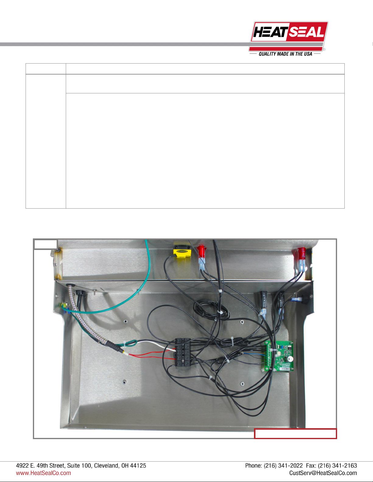
TROUBLESHOOTING
200ES Electrical Box Pictured
Figure 1
Symptom Possible Solution
No power to
the unit.
Verify the unit is plugged into a 15 Amp circuit, and the Power Switch is set to the “ON” position.
Is the GFCI circuit breaker tripped?
1) Remove “Non-Stick” Cover and inspect the Seal Plate for the following defects:
Punctures or cuts.
Burn marks.
Discoloration.
If these defects are present, replace seal plate.
2) If seal plate is in good condition, reset GFCI. If GFCI cannot be reset, replace the GFCI.
3) Reset new GFCI. Red Power Light at right front of unit SHOULD glow.
4) If GFCI trips, seal plate may have moisture inside. Allow 1-2 days to dry out and then retry.

9
Revised 2019
TROUBLESHOOTING
Symptom Possible Solution
Unit has power
but the Seal Plate
does not work
Verify power. Does the LED light turn ON when photo eye is triggered?
1) If neither the LED or Seal Plate work, verify that the 20 Amp Circuit Breaker has not
tripped.
2) If the Circuit Breaker has tripped, verify there are no shorts to ground in the unit by
checking wiring and connections (on page 8). Reset Circuit Breaker.
3) Replace Circuit Breaker if it cannot be reset.
Verify the Photo eye is working properly.
1) With the Power ON, there should be a Green Light illuminated on the back of the
Photo Eye. When the Photoeye is triggered a separate Yellow Light will illuminate.
2) If the green light is ON and the yellow light does NOT illuminate when the Photo
Eye is triggered, replace the Photo Eye.
3) If green light is NOT illuminated when power is ON, check Control Board to
determine if Photo Eye or Control Board is faulty.
Verify the control board is working.
1) Check the voltage on Pin 1 of the Control Board using a multimeter. If it is not
120vac, a wiring issue exists. Find and repair.
2) Check voltage across Pin 4 & 5, (Brown & Blue Wires) this voltage should be 10 to
30vdc.
If NO voltage present, replace Control Board.
If voltage present, replace Photo Eye.
Verify seal plate. If the plate does not heat at all or is only slightly warm to the touch,
replace the Seal Plate.
Film Cut-off Rod
does not work at
all.
Verify the unit is plugged into a 15 Amp circuit and the Power Switch is set to the “ON”
position.
Verify that the 1 Amp circuit breaker is not tripped. If the circuit breaker is tripped, then reset
and verify there are no shorts to ground in the unit by checking wiring and connections.
Film cuts too
slowly
Clean Cut-off Rod surface and verify it is not bent. See “Cut-Off Rod” Maintenance.
10
Revised 2019
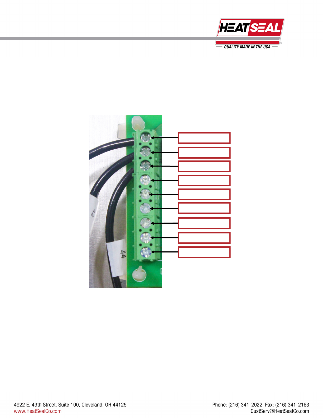
CONTROL BOARD ASSEMBLY
NEUTRAL
HEATER OUT
24V
0V
AUX
PRODUCT DETECTION
(+) THERMISTOR
(-) THERMISTOR
120 VAC
11
Revised 2019
CONTROL BOARD ASSEMBLY
12
Revised 2019
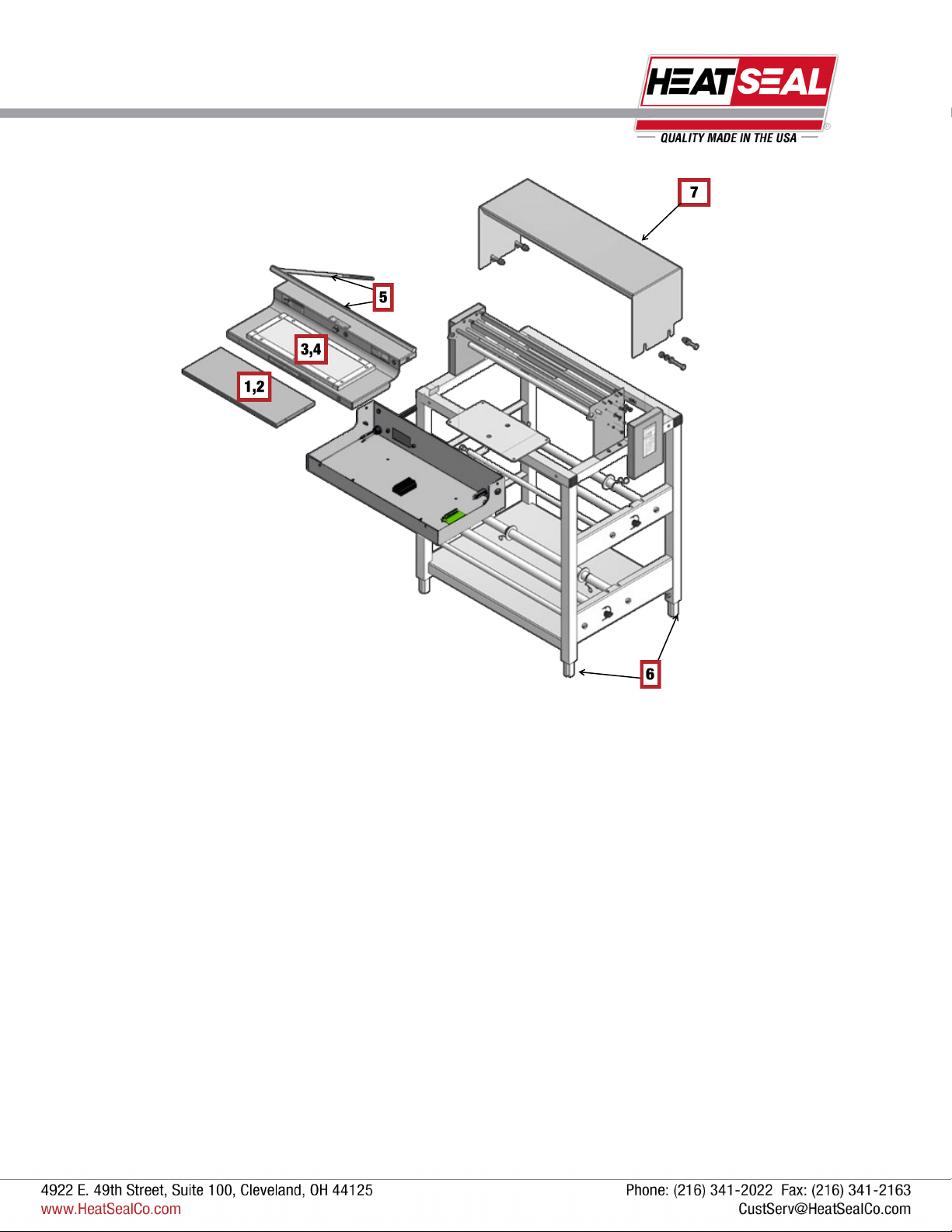
SERVICE PARTS INFORMATION
BILL OF MATERIALS FOR MAJOR ASSEMBLIES
ITEM QTY PART NUMBER DESCRIPTION
1 1 5901-011 Non-stick Cover, 6 x 15
2 1 5901-001 Non-stick Cover, 8 x 15
3 1 6137-149 Replacement 6 x 15 Seal Plate Kit
4 1 6137-150 Replacement 8 x 15 Seal Plate Kit
5 1 6137-094 Hot Rod Replacement Kit Includes: (1) Square Boardless Cut Off Rod with (1) O-Ring and (1)
Strain Relief Grommet
6 4 2135-040 Foot Glide
7 1 6137-076 Stainless Steel Wrapping Bridge, 200ES

13
Revised 2019
SERVICE PARTS INFORMATION
1
2
3
BILL OF MATERIALS FOR ELECTRICAL BOX
ITEM QTY PART NUMBER DESCRIPTION
1 1 1818-035
1818-036
6” x 15” Energy Smart® Control Board, Programmed
8” x 15” Energy Smart® Control Board, Programmed
2 1 6340-070 Circuit Board Mounting Kit Includes: (4) Plastic Clip Stand-Offs
3 1 1875-055 Terminal Block
4 1 1815-030 1A Circuit Breaker
5 1 1815-031 20A Circuit Breaker
6 1 1872-123 GFCI Blank Outlet, 20A/125V
7 1 1872-131 20A Rocker Switch
8 1 6340-069 Power Cord Replacement Kit Includes: (1) Strain Relief, (1) 7’ Power Cord
7
4
6 8
5
Table of contents
Other Heat Seal Stretch Wrapping System manuals


