Heath Company Heathkit H8 User manual
Heathkit® Manual
for the
DIGITAL COMPUTER
Model H8
ASSEMBLY 595-2013-01
: --
--
HEATH
COMPANY
BENTON
HARBOR,
MICHIGAN
49022
Copyright
© 1977
Heath Company
All Rights Reserved
Printed
in
the United States of America
Page
2
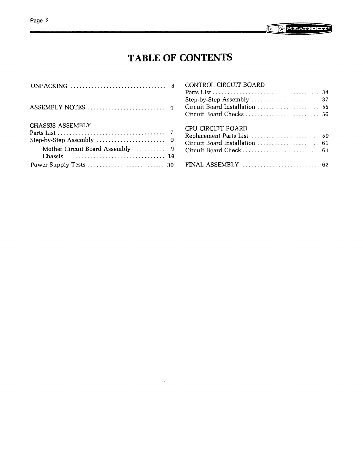
TABLE OF CONTENTS
UNPACKING
................................
3 CONTROL CIRCUIT BOARD
Parts
List.
. . . . . . . . . . . . . . . . . . . . . . . . . . . . . . . . .
..
34
Step-by-Step Assemlbly
.......................
37
ASSEMBLY NOTES . . . . . . . . . . . . . . . . . . . . . . . .
..
4 Circuit Board Installation
...................
"
55
Circuit Board Checks
.........................
56
CHASSIS ASSEMBLY
Parts List . . . . . . . . . . . . . . . . . . . . . . . . . . . . . . . . . .
..
7
Step-by-Step Assembly
.......................
9
CPU CIRCUIT BOARD
Replacement Parts List
.....
. . . . . . . . . . . . . . . .
..
59
Circuit Board Installation
.....................
61
Mother Circuit Board Assembly
............
9 Circuit Board Check
..........................
61
Chassis
.................................
14
Power
Supply
Tests.
. . . . . . . . . . . . . . . . . . . . . . .
..
30 FINAL ASSEMBLY
..........................
62
UNPACKING
Your Digital
Computer
shipping
carton
contains
a
box
marked
"CPU
Circuit
Board"
and
a
smaller
box
marked
"Pack
#2."
After
you
remove
these
two
boxes,
the
remaining
parts
in
the
shipping
carton
form
the
Main
Pack,
which
are
items
too
large
to
fit
into
the
other
parts
packs
and
those
items
which
you
will
use
in
the
chassis
assembly
section.
Set
aside
the
boxes
marked
"CPU
Circuit
Board"
and
"Pack
#2"
until
one
of
these
packs
is
called
for
in
an
assembly
section. DO NOT
disturb
either
of
these
packs
yet.
Page 3
Each
assembly
section
of
this
Manual
contains
its
own
"Parts
List"
and
"Step-by-Step
Assembly"
in-
structions.
At
the
beginning
of
each
Parts
List,
you
will
be
instructed
which
parts
pack
to
locate
and
unpack.
You
may
also
be
directed
to locate
certain
required
parts
from
the
Main
Pack.
To
avoid
intermixing
parts,
do
not
remove
or
open
any
of
the
parts
packs
until
you
are
directed
to
do
so
at
the
beginning
of
one
of
the
"Parts
Lists."
Return
any
part
that
is
packed
in
an
individual
envelope,
with
the
part
number
on
it,
back
in
its
envelope
after
you
identify
it
until
that
part
is
called
for
in
a step.
Some
envelopes
have
one
transparent
side
so
you
can
iden-
tify
the
parts
inside
without
opening
the
envelope.
Page 4
ASSEMBLY NOTES
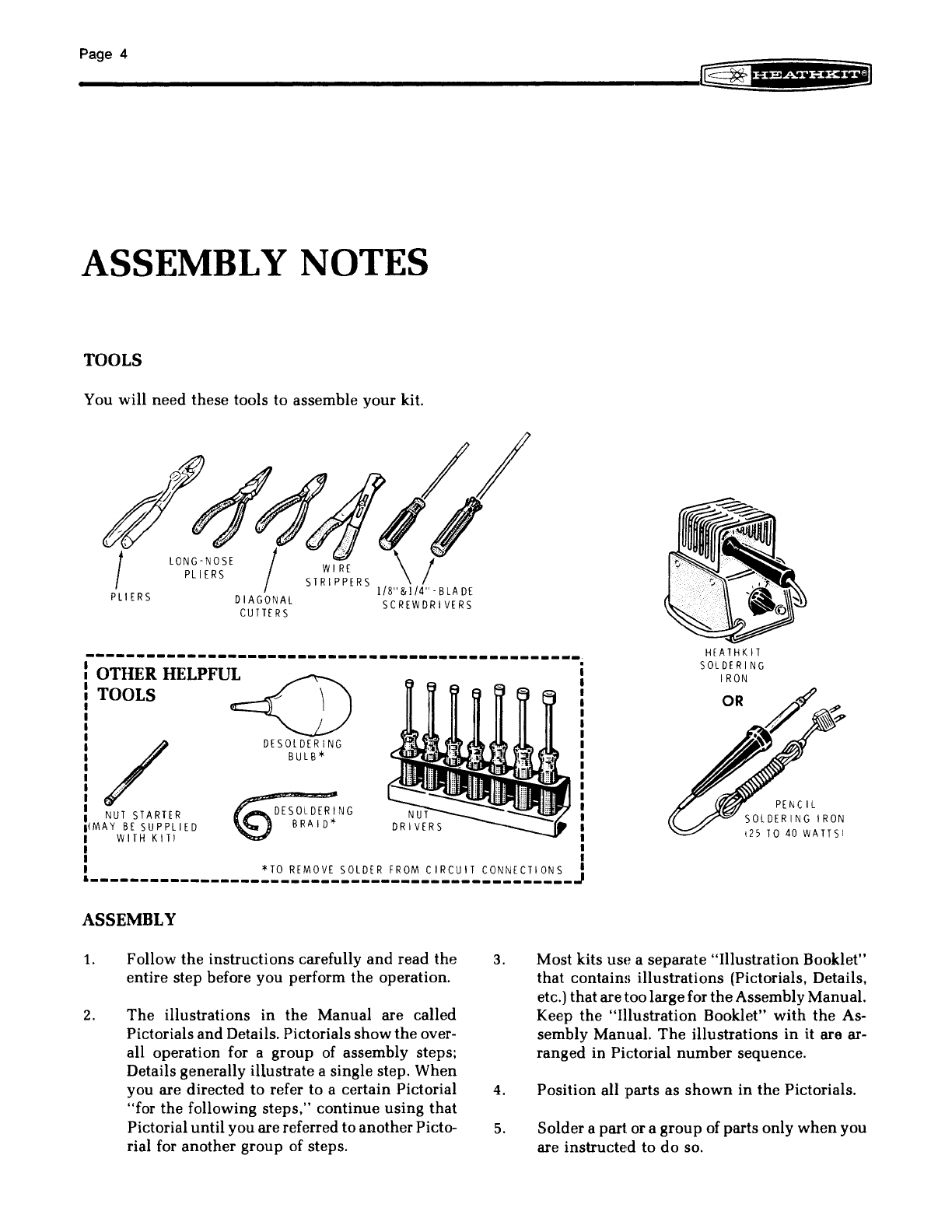
TOOLS
You
will
need these tools to assemble
your
kit.
~~
~-A(
d!
//
~
tf'J
rJ
tlJI
~
.....
I LONG-NOSE I
WI
RE
\ I
PLIERS STRI
PPERS
1/8"
&1/4"
-
BLA
DE
PLIERS DIAGONAL SCREWDRIVERS
CUTTERS
-------------------------------------------------
OTHER
HELPFU~
TOOLS
~
/ DESOLDERING
BULB*
NUT
STARTER
IIMAY
BE
SUPPLIED DESOLDERING
BRAID*
I WITH
KITI
I
I
HEATHKIT
SOLDERING
I
RON
OR
,25
TO
40
WATTSI
I
*TO
REMOVE
SOLDER
FROM
CIRCUIT
CONNECTIONS
I
________________________________________________
~
ASSEMBLY
1.
2.
Follow
the
instructions
carefully
and
read
the
entire step before you perform
the
operation.
The
illustrations in
the
Manual are called
Pictorials
and
Details. Pictorials
show
the
over-
all operation for a
group
of assembly steps;
Details generally illustrate a single step.
When
you are directed
to
refer to a certain Pictorial
"for
the
following
steps,"
continue
using
that
Pictorial
until
you are referred
to
another
Picto-
rial for
another
group of steps.
3.
4.
5.
Most kits use a separate
"Illustration
Booklet"
that contains illustrations (Pictorials, Details,
etc.) thataretoo largefor
the
AssemblyManual.
Keep
the
"Illustration
Booklet"
with
the
As-
sembly Manual.
The
illustrations
in
it are ar-
ranged
in Pictorial
number
sequence.
Position all parts as
shown
in
the
Pictorials.
Solder
a part or a
group
of parts only
when
you
are instructed to
do
so.

6.
= =
~
Each circuitpart
in
an
electronickit hasits
own
component number
(R2,
C4, etc.). Use these
numbers
when
you
want
to
identify
the
same
part
in
the
various sections of
the
Manual.
Thesenumbers,
which
areespeciallyuseful ifa
part has to be replaced, appear:
In
the
Parts List,
At
the
beginning of each step where a
component is installed,
In some illustrations,
In
the
Schematic,
In the section
at
the
rear
Df
the
Manual.
7. When you are instructed to
cut
something to a
particular length,
use
the
scales (rulers) pro-
vided at
the
bottom of
the
Manual pages.
SAFETY WARNING: Avoid eye
injury
when you
cut
offexcess lead lengths. Hold
the
leads
so
they
cannot
fly
toward
your
eyes.
Page 5
SOLDERING
Soldering is one ofthemost importantoperationsyou
will perform while assembling your kit. A good sol-
der connection will form
an
electrical connectionbe-
tween
two
parts, such as a component lead
and
a
circuitboard foil. A bad solder connectioncould pre-
vent
an
otherwise well-assembled kit from operating
properly.
It
is easy to make a good solder connection if you
follow a few simple rules:
1.
2.
Use
the
right type of soldering iron. A 25 to
40-watt pencil soldering iron
with
a 1/8" or
3/16"
chisel or pyramid tip works best.
Keep
the
soldering irontip clean. Wipe it often
on a wet sponge or cloth;
then
apply solder
to
the
tip
to
give
the
entire
tip
a wet look. This
process is calledtinning.
and
it will protect
the
tip
and
enable you
to
make good connections.
Whensolder
tends
to
"ball"
or does not stick
to
the
tip. the tip needs
to
be
cleaned
and
retin-
ned.

Page 6
PARTS
Resistors will
be
called
out
by
their
resistance
value
in
0 (ohms). kO (kilohms),
orMO
(megohms). Certain
types of resistors will have
the
value
printed
on
the
body, while others will be identified by a color code.
The
colors of
the
bands
and
the
value
will
be
given in
the
steps, therefore
the
following color
code
is given
for information only.
==
l/4-WATT
==fDIII~==
l/2-WATT
l-WATT
EXAMPLES:
==
..
~==
/
BROWN
__
GREEN
---
ORANGE
~
SILVER
5
1.000
±10%
15 x 1,000 =
15,0000
(15,000 OHMS),
or
"15 kO"
/ ORANGE 3
__
BLACK 0
---
GREEN
100,000
"'"
GOLD
::+:5%
30 x 100,000 = 3,000,000 0
(or
3 MO)
3
MO
= 3 MEGOHMS
2-WATT
TOLERANCE
RESISTOR COLOR CODE
II'.
*-----===i
Gold
5%
Silver 10%
.-~
l I No Band 20%
•
COLOR
1st
DIGIT
2nd
DIGIT
MULTIPLY
BY
BLAC K a a 1
BROWN I 1
10
RED
2 2
100
ORANGE l l
I,
000
YE
LL
OW
4 4
10
,000
GREEN
5 5 100,000
BLUE
6 6 1,000,000
VIOLET 7 7 10,000,000
GRAY 8 8 100,000,000
WH
IT[
9 q 1,000,000,000
GOLD
1
SI L
VE
R
01
Capacitors
will
be
called
out
by
their
capacitance
value
in,."F (microfarads) or pF (picofarads)
and
type:
ceramic,
Mylar·,
electrolytic,
etc_
Some capacitors
may
have
their
value
printed
in
the
following man-
ner:
EXAMPLES:
151K
=
15
x
10
=
150
pF
759
=
75
x
0.1
=
7.5
pF
First digit
of
capacitor's value: 1
--
__
....
Second
digit of
capacitor's value: 5
____
oJ
Multiplier: Multiply
the
___
--I
first & second digits by
the
proper value from the
Multiplier Chart.
To find the tolerance of
-----J
the capacitor, look
up
this
letter in the Tolerance
columns.
·DuPont
Registered
Trademark
NOTE:
The
letter
"R"
may be
used
at
timesto signify a
decimal point; as in: 2R2 = 2,2 (pF
or
,."F).
MULTIPLIER
TOLERANCE
OF
CAPACITOR
FOR
THE
MULTIPLY
lOp F
OR
LETTER
OVER
NUMBER
BY
LE5 S
10pF
0 I
to
1PF B
1
10
±0.25pF
C
2
100
to.
5pF
D
3 1000 ±I
OpF
F ±I %
4
10,000
±2
OpF
G ±
2'7,
5
100,000
H
±3'70
J t5%
g
0.01
K ±
10%
9
O.
1 M
±20%
Page
7
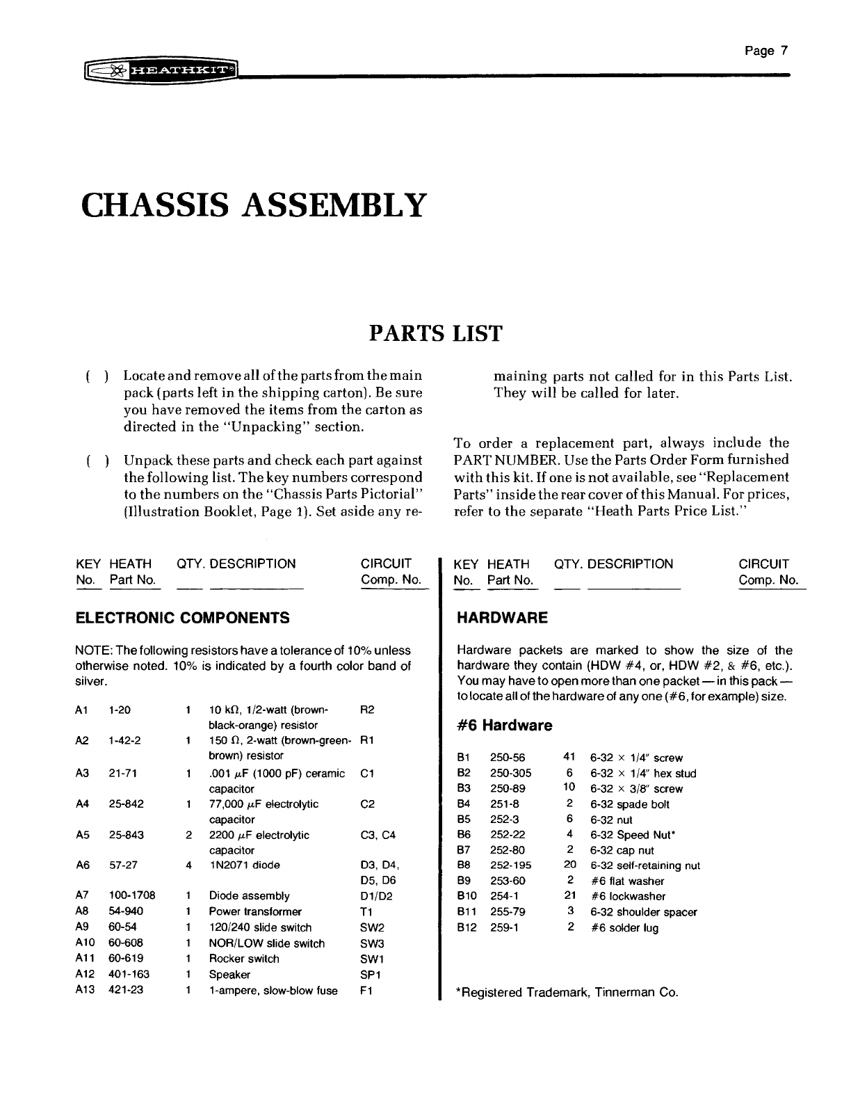
CHASSIS ASSEMBLY
PARTS LIST
( ) Locate
and
remove
all
of
the
partsfrom
the
main
pack
(parts left
in
the
shipping
carton). Be
sure
you
have
removed
the
items
from
the
carton
as
directed
in
the
"Unpacking"
section.
Unpack
these
parts
and
check
each part
against
the
following list.
The
key
numbers
correspond
to
the
numbers
on
the
"Chassis
Parts
Pictorial"
(Illustration Booklet,
Page
1).
Set
aside
any
re-
KEY
HEATH
No.
Part
No.
QTY.
DESCRIPTION
CIRCUIT
Compo No.
ELECTRONIC COMPONENTS
NOTE:
The
following resistors
have
a
tolerance
of
10%
unless
otherwise
noted.
10%
is
indicated
by
a fourth
color
band
of
silver.
A1
1-20
10
kfl,
1/2-watt (brown-
R2
black-orange) resistor
A2
1-42-2 150
fl,
2-watt (brown-green-
R1
brown) resistor
A3
21-71
.001
fotF
(1000
pF)
ceramic
C1
capacitor
A4
25-842 77,000
fotF
electrolytic
C2
capacitor
A5
25-843 2 2200
fotF
electrolytic
C3,C4
capacitor
A6
57-27 4 1
N2071
diode
03,04,
05,
06
A7
100-1708 Oiode assembly
01/02
A8
54-940 Power transformer
T1
A9
60-54 120/240 slide switch SW2
A10 60-608 NOR/LOW slide switch SW3
A11
60-619 Rocker switch
SW1
A12
401-163 Speaker
SP1
A13
421-23 1-ampere, slow-blow fuse
F1
maining
parts
not
called
for
in
this
Parts List.
They
will
be
called for later.
To
order
a
replacement
part, always
include
the
PART NUMBER. Use
the
Parts
Order
Form
furnished
with
this
kit.
If
one
is
not
available, see
"Replacement
Parts"
inside
the
rear
cover
of
this
Manual. Forprices,
refer to
the
separate
"Heath
Parts Price List."
KEY
HEATH
No. Part No.
HARDWARE
QTY.
DESCRIPTION
CIRCUIT
Compo No.
Hardware
packets
are
marked
to
show
the
size of
the
hardware
they
contain
(HOW
#4,
or,
HOW
#2,
&
#6,
etc.).
You
may
have
to
open
more
than
one
packet
-in this
pack-
to
locate
all of
the
hardware
of
anyone
(#6,
for
example)
size.
#6
Hardware
B1
250-56
41
6-32 x 1/4" screw
B2
250-305 6 6-32 x 1/4" hex stud
B3
250-89
10
6-32 x 3/8" screw
B4
251-8 2 6-32 spade bolt
B5
252-3 6 6-32 nut
B6
252-22 4 6-32 Speed
Nut'
B7
252-80 2 6-32 cap nut
88
252-195
20
6-32
self-retaining nut
B9
253-60 2
#6
flat washer
810
254-1
21
#6
lockwasher
811
255-79 3 6-32 shoulder spacer
812
259-1
2
#6
solder lug
*Registered
Trademark,
Tinnerman
Co.

PageS
KEY
HEATH
OTY.
DESCRIPTION
No.
Part
No.
Hardware (cont'd.)
#8
Hardware
Cl
250-98 6 8-32 x1/2" screw
C2 252-4 6 8-32 nut
C3 252-706 4 8-32 lock nut
C4 253-45 4
#8
flat washer
C5 254-2 6
#8
lockwasher
Other Hardware
Dl
250-1256 2 10-32 x 1/4" screw
D2
254-3 2 #
10
lockwasher
D3 259-26 4
#10
solder lug
D4
252-193 2 Push-on nut
D5 259-22 Spade lug
06
253-8 Brass flat washer
SHEET METAL PARTS
El
200-1296-1 Chassis
E2
203-1891-1 Top cover
E3
203-1892-1 1 Front panel
E4
204-2265 2 Circuit board mounting
bracket
E5 204-2267-1 Cable clamp
E6
204-2292 Tie bracket
E7 206-1249 AC shield
E8
206-1250 Capacitor shield
E9
207-98 Capacitor mounting strap
E10 207-622 Circuit board support clamp
WIRE
344-7 1'6" Large black wire
344-33
2'
Medium black wire
344-111 6'3" Orange wire
344-118 1'3" Large red wire
344-120 2'6" Small black wire
344-121 4' White wire
347-55 7'fJ' 8-wire cable
89-54 Line cord
0
y..
% %
(INCHES)
2
1'(8 I
3:8
I
5{B
I
7;8
I , I I I I I, I
I ! i I i !
"if
i
I"
i)
i I i
0 5 1
(eM)
2 3 4 5 6
CIRCUIT
Compo
No.
3
KEY
HEATH
OTY.
DESCRIPTION
CIRCUIT
No.
Part
No.
Compo
No.
PRINTED
MATERIIAL
Fl
390-1357 Model label
390-1415 Instruction card
F2 390-926 Warning label
F3 391-34 Blue and white label
F4 391-611 Nameplate
F5 390-1371 Keyboard label set
597-260 Parts Order Form
597-1656 Heath User's Group
(HUG) Application
597-1659 HUG return envelope
Assembly Manual (See
Page 1 for part number.)
Operation Manual (See
Page 1 for part number.)
Software Manual (See
Page 1 for part number.)
MISCELLANEOW,
G1
354-7 2 Large cable tie
G2 73-3 1 Rubber grommet
G3 261-20 4 Rubber foot
G4 352-31 Thermal compound*
G5 423-11 Fuseholder
G6 434-148 1 AC socket
G7 432-946 20 25-pin plug
G8 75-736 1 Strain relief
G9 432-120 2 PCB connector
Gl0
73-39
18"
Foam tape
G111
490-5 Nut starter
Gl'!
490-111 IC lifter
Gl~1
490-185 Package of Soder Wick*-
203-1879 Set of side panels
containing:
G14
203-1877 Right side
panel
G1ti 203-1878 Left side
panel
G1E>
446-683 Window
GH
354-5 Small cable tie
85-1936-1 Mother circuit board
701-29 3-ring binder
703-12 Set of 5 tabs (for
binder)
880-1 System software
cassette tape (Assember,
Editor, Basic, Debug)
Solder
*Dow
Corning
thermal
heat
sink
compound
contains
Zinc
Oxides,
Si0
2,
and
slight
traces
of
CO
2,
**I~egistered
Trademark,
Solder
Removal
Company
4 5 6 7
iii
I ! I i
I I i I i I i Ii I
i i I
I ! i I I I i i I
I i i I i I I II i ! I I I
I
8 9
10
11
12
13
14
15
16
17
Page
9
STEP.BY·STEP ASSEMBLY
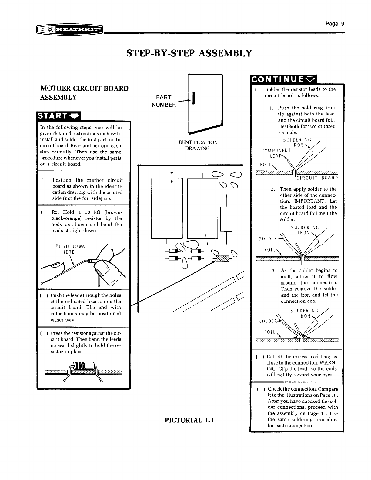
MOTHER CIRCUIT BOARD
ASSEMBLY
In
the
following
steps,
you
will
be
given
detailed
instructions
on
how
to
install
and
solder
the
first
part
on
the
circuit
board. Read
and
perform
each
step
carefully.
Then
use
the
same
procedure
whenever
you
install
parts
on
a
circuit
board.
[ )
Position
the
mother
circuit
board
as
shown
in
the
identifi-
cation
drawing
with
the
printed
side
[not
the
foil side)
up.
( )
R2:
Hold
a 10
kO
(brown-
black-orange) resistor by
the
body
as
shown
and
bend
the
leads
straight
down.
( )
Push
the
leads
through
the
holes
at
the
indicated
location
on
the
circuit
board.
The
end
with
color
bands
may
be
positioned
either
way.
( )
Press
the
resistor
against
the
cir-
cuit
board.
Then
bend
the
leads
outward
slightly
to
hold
the
re-
sistor
in
place.
PART
NUMBER
1+
+
I
IDENTIFICATION
DRAWING
+
PICTORIAL 1-1
CONTI
NUEv
. ( )
Solder
the
resistor
leads
to
the
circuit
board
as follows:
1.
Push
the
soldering
iron
tip
against
both
the
lead
and
the
circuit
board
foil.
Heatboth for
two
or
three
seconds.
SOLDERING
I
RON
COMPONENT
~
~~~ClRCUIT
BOARD
2.
Then
apply
solder
to
the
other
side
of
the
connec-
tion.
IMPORTANT: Let
the
heated
lead
and
the
circuit
board
foil
melt
the
solder.
3. As
the
solder
begins
to
melt,
allow
it
to
flow
around
the
connection.
Then
remove
the
solder
and
the
iron
and
let
the
connection
cool.
SOLDERING
I
RON
FO
IL
( ) Cut off
the
excess
lead
lengths
close
to
the
connection.
WARN-
ING: Clip
the
leads
so
the
ends
will
not
fly
toward
your
eyes.
Check
the
connection.
Compare
it
to
the
illustrations
on
Page
10.
After
you
have
checked
the
sol-
der
connections,
proceed
with
the
assembly
on
Page
11.
Use
the
same
soldering
procedure
for
each
connection.
Page
10
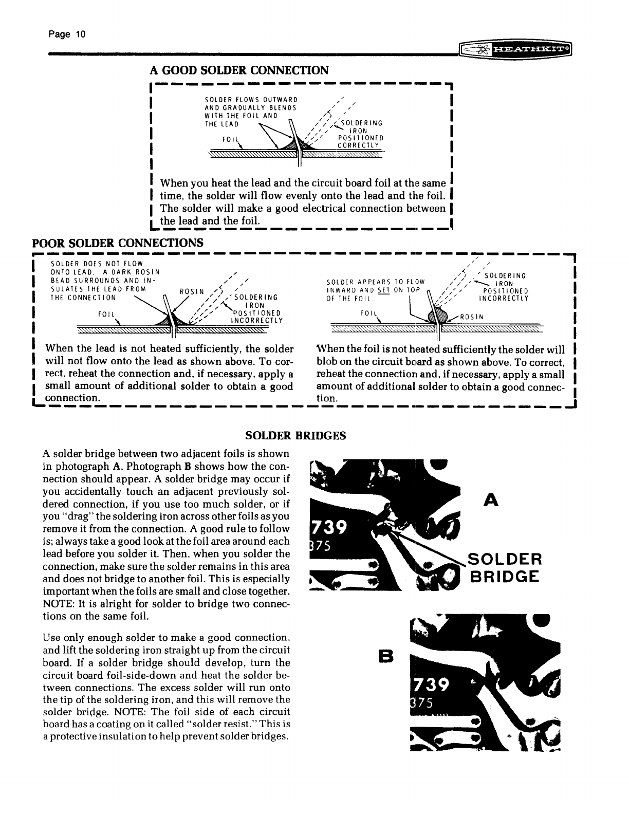
A GOOD SOLDER CONNECTION
1-------------------,
I
I
I
I
I
SOLDER
FLOWS
OUTWARD
AND
GRADUALLY
BLENDS
WITH
THE
FOIL
AND
THE
LEAD
I
I
I
I
I
I
When
you
heat
the
lead
and
the
circuit
board
foil at
the
same I
I time.
the
solder will flow evenly
onto
the
lead
and
the
foil. I
I
The
solder will make a good electrical
connection
between I
L.
t!!!:
~'!.!r!!,
~
.!!!i~
________
__
.
__
~
POOR SOLDER CONNECTIONS
-----------------------------~-----,
I
SOLDER
DOES
NOT
FLOW
,./
,.
I
ONTO
LEAD. A DARK
ROSIN,.
,.~
'/SOLDERING
I
BEAD
SURROUNDS
AND
IN-
,/
,./
SOLDER
APPEARS
TO
FLOW
///.---..
IRON I
SULATES
THE
LEAD
FROM
ROSIN
/~
/ INWARD
AND
SET
ON
TOP
///
/ POSITIONED
I
THE
CONNECTION
//
/ SOLDERING
OF
THE
FOIL. -l
////
INCORRECTLY I
///"'-
IRON
:
FOil
l:~"
1~~SoIJ~rNlDy
~;:;:;0W:;~':;::;Z'2&:§:'2""""""
VROSIN
I
I I
I
When
the
lead is not
heated
sufficiently.
the
solder
When
the
foil is not heated sufficiently
the
solder will
II
will not flow onto
the
lead as
shown
above.
To
cor- blob on
the
circuit board as
shown
above. To correct.
I
recto
reheat the
connection
and. if necessary.
apply
a reheat
the
connection and, ifnecessary.
apply
a small I
I small
amount
of
additional
solder
to obtain a good
amount
of
additional
solder to obtain a good connec- 1
Lconnection. tion. I
------------------------------------"
SOLDER
BRIDG)~S
A solder bridge
between
two
adjacent foils is
shown
in photograph
A.
Photograph
B
shows
how
the
con-
nection
should
appear. A solder bridge may occur if
you
accidentally
touch
an
adjacent previously sol-
dered
connection, if
you
use
too
much
solder. or if
you
"drag"
the
soldering iron across
other
foils asyou
remove it from
the
connection. A good
rule
to follow
is; always take a good lookat
the
foil area
around
each
lead before you solder it.
Then.
when
you solder
the
connection, make sure
the
solderremains
in
this
area
and
does not bridge to
another
foil.
This
is especially
important
when
the
foils aresmall
and
closetogether.
NOTE:
It
is alright for solder to bridge
two
connec-
tions on
the
same foil.
Use only
enough
solder to make a good connection.
and
lift
the
soldering iron straight
up
from
the
circuit
board.
If
a solder bridge
should
develop,
turn
the
circuit hoard foil-side-down
and
heat
the
solder be-
tween
connections.
The
excess solder will
run
onto
the
tip of the soldering iron.
and
this will remove
the
solder bridge. NOTE:
The
foil
side
of each circuit
board has a coating
on
it called
"solder
resist."
This
is
a protectiveinsulationtohelp preventsolderbridges.
B
A
SOLDER
BRIDGE

~
~f§f%i§B*fj]
Installtwo 25-pin
plugs
at each
of
the
following locations:
Pl0
..........................
.
P9
..........................
.
) P8.
P7
..........................
.
P6
..........................
.
) P5.
) P4
..........................
.
)
P3.
)
P2.
) P1.
) Visually
check
each
plug
for
solder bridges.
Page
11
PICTORIAL 1-2

Page
12
NOTE: Make
sure
you
have
installed
the
resistor
in
Pictorial 1-1.
( ) R1: 150 .0,
2-watt
[brown-
green-brown). Form
the
resistor
leads as necessary to fit
the
cir-
cuit
board
holes.
NOTE:
When
you install a
diode,
position its
banded
end
as
shown
in
the
Pictorial. A
circuit
will
not
oper-
ate
properly
if
the
diode
is
installed
backward.
~
0
\ I
V
.(
BANDED
END
D3: 1N2071
diode
(#57-27).
D6:
1N2071
diode
(#57-27).
D5: 1N2071
diode
(#57-27).
)
D4:
1N2071
diode
(#57-27).
y.
Solder
the
leads to
the
foil
and
cut
off
the
excess lead lengths.
Y2
%
(INCHES)
I
'(8
I
3;8
111'1"111
I
5i
B
I
i I
7
~8
I
I I I I I I I
0 5 ,
(eM)
2 3 4
2
I
I
5
I i Ii I i
6
PICTORIAL 1-3
3 4
I II i I I
I I I I I I II I
I I
8 9
10
"
'2
CONTINUE
0-
I
NOTE: As you
wire
this kit, you will
be
instructed
to
prepare
lengths
of
wire
ahead
of time, as
in
the
follow-
ing step.
To
prepare
a wire,
cut
it to
the
indicated
length
and
remove
1/4"
of
insulation
from each end.
Then
melt
a
small
amount
of
solder
on
the
bare
wire
ends
to
hold
the
small
strands
of
wire
together.
( )
Prepare
the
following wires:
11" large
red
11"
large black
Install
the
prepared
wires
in
the
fol-
lowing steps.
Solder
each
wire
to
the
foil as you install it
and
cut
off
the
excess wire end.
The
other
end
of
the
wire
will be
connected
later.
11"
red.
11"
black.
5 6
I I I i I I I i I
i i I I II I I I I
'3
'4
'5
'6
17
7
I

NOTE:
When
you
install
an
elec-
trolytic capacitor, always
position
the
plus
(+)
marked
end
of
the
capacitor
toward
the
plus
mark
on
the
circuit
board.
( ) C3:
2200
f.LF
electrolytic
capacitor.
( ) C4:
2200
f.LF
electrolytic
capacitor.
( )
Solder
the
leads
to
the
foil
and
cut
off
the
excess
lead
lengths.
PICTORIAL 1-4
Page
13
CONTINUEQ
( )
Thread
a large cable
tie
through
the
holes in
the
circuit
board
and
around
capacitor C4. Make
sure
the
rough
side
of
the
cable
tie
is
toward
the
capacitors.
Then
pull
the
cable
tie
tight
and
cut
off
the
excess length.
CABLE
TIE
In
the
same
manner,
install a
large cable
tie
around
capacitor
C3.
( ) Use
an
ohmmeter
to
check
for
unwanted
shorts
between
each
adjacent
pin
at
any
of
the
50-pin
plugs
(two
25-pin
plugs).
NOTE:
Pins
0
and
1,
and
pins
48
and
49
are
connected
together;
these
should
show
up
as shorts.
CIRCUIT BOARD CHECKOUT
Carefully
inspect
the
foil
side
of
the
circuit
board
for
the
following most
commonly
made
errors.
Unsoldered
connections.
Poor
solder
connections.
Solder
bridges
between
foil pat-
terns.
( )
Protruding
leads
which
could
touch
together
or
the
chassis
when
the
circuit
board is instal-
led later.
Refer to
the
illustrations
where
the
parts
were
installed
as you
make
the
following
visual
checks.
( ) Electrolytic capacitors for
the
correct position
of
the
positive
(+)
mark.
( ) Diodes for
the
correct orienta-
tion.
Set
the
circuit
board
aside
until
it is
called
for
in
a step.
FINISH

Page
14
CHASSIS
RUBB
ER
FOO
T
8-32
x
ll2
"
SC
RE
W
Detail
2~lA
Refer to Pictorial
2-1
(Illustration Booklet. Page
3)
for
the following steps.
( ) Position the chassis as
shown
in the Pictorial.
NOTE:
When a step calls for hardware.onlythescrew
size is given. For instance, if"6-32 x 3/8" hardware"
is called for, it means you should use a 6-32 x 3/
8"
screw, one or more lockwashers, and a 6-32
nut
at
each mounting hole.
The
detail referred to in the step
shows
the
proper
number
and
placement
of
lockwashers.
( ) Refer to Detail2-1A and
mount
a rubber foot on
the bottom ofthe chassis at AA. Use 8-32 x 1/
2"
hardware_
( ) Similarly. mount rubber feet on
the
bottom of
the chassis at
AB, AC,
and
AD.
Use 8-32 x 1/2"
hardware.
( ) Scrape or sand any excess paint from around
holes
AE
and AF on the
inside
of the chassis.
Detail 2-18
NOTE:
Use the plastic
nut
starter supplied with this
kit to hold and start 4-40
and
6-32 nuts on screws.
( ) Refer to Detail2-1B
and
mount a
#6
solder lug
at
AE.
Use
6-
32 x 1/
4"
hardware and be sure to
position the solder lug as shown in the Picto-
rial.
( ) Similarly, mount a
#6
solder lug at AF with
6-32 x 1/
4"
hardware.
( ) Refer to Detail2-1C and mount thecable clamp
on
the
rear of the chassis at
AG.
Use two 6-32 x
3/8" screws and two
#6
flat washers. Be sureto
position the lip on the clamp as shown.
Slide
the clamp down as far as possible before you
tighten the screws.
Detail 2-1C
6-32x3/S
"
SC
REW
•
•
•
Page
15
f6-32xIl4"
SCREW
~
#6 LOCKWASHER
~
:
CIRCUIT
BOARD
6-32 SELF-
'"
.'
I '" MOUNTING BRACKET
RET~~~IEN~)
NUT~
I
"
r9
~-l
Ii
(21
~,
t
~~LEFT
~~t:'
p SIDE PANEl
//' '
~(B~:~
______________________
~
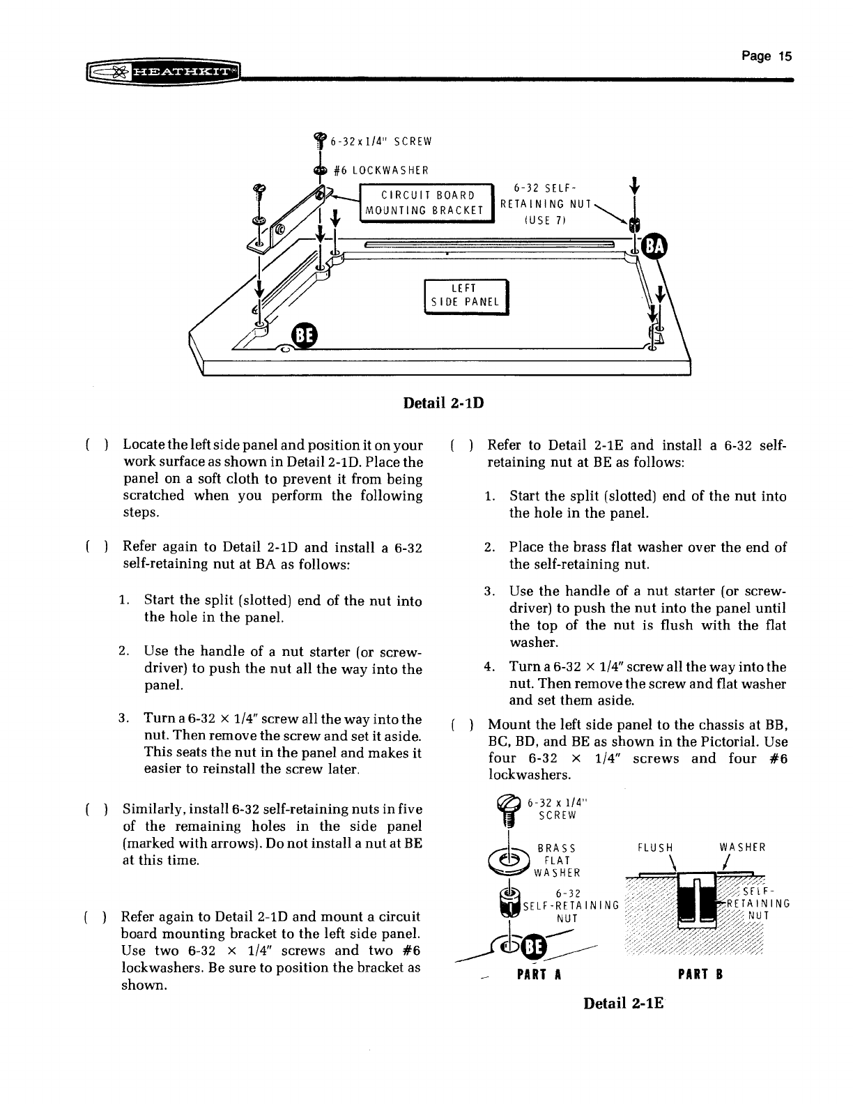
Detail2-1D
( ) Locate
the
left
side
panel
and
position
it
on
your
work
surface as
shown
in
Detail 2-1D. Place
the
panel
on
a soft
cloth
to
prevent
it from
being
scratched
when
you
perform
the
following
steps.
( ) Refer
again
to Detail 2-1D
and
install a 6-32
self-retaining
nut
at
BA
as
follows:
1.
Start
the
split
(slotted)
end
of
the
nut
into
the
hole
in
the
panel.
2.
Use
the
handle
of a
nut
starter (or screw-
driver) to
push
the
nut
all
the
way
into
the
panel.
3.
Turn
a 6-32 x 1/4"
screw
all
the
way
into
the
nut.
Then
remove
the
screw
and
set
it
aside.
This
seats
the
nut
in
the
panel
and
makes
it
easier to reinstall
the
screw
later.
( ) Similarly, install 6-32 self-retaining
nuts
in
five
of
the
remaining
holes
in
the
side
panel
(marked
with
arrows). Do
not
install
a
nut
at
BE
at
this
time.
( ) Refer
again
to Detail 2-1D
and
mount
a circuit
board
mounting
bracket to
the
left
side
panel.
Use two 6-32 x 1/4"
screws
and
two
#6
lockwashers. Be
sure
to
position
the
bracket as
shown.
( ) Refer to Detail 2-1E
and
install a 6-32 self-
retaining
nut
at
BE
as follows:
1. Start
the
split
(slotted)
end
of
the
nut
into
the
hole
in
the
panel.
2.
Place
the
brass flat
washer
over
the
end
of
the
self-retaining nut.
3.
Use
the
handle
of a
nut
starter (or screw-
driver) to
push
the
nut
into
the
panel
until
the
top
of
the
nut
is flush
with
the
flat
washer.
4.
Turn
a 6-32 x 1/4"
screw
all
the
way
into
the
nut.
Then
remove
the
screw
and
flat
washer
and
set
them
aside.
( )
Mount
the
left
side
panel
to
the
chassis
at
BB,
Be,
BD,
and
BE
as
shown
in
the
Pictorial. Use
four
6-32 x 1/4"
screws
and
four
#6
lockwashers.
~
6-32 x
1/4"
11
SCREW
®
BRASS
~
FLAT
WA
SHER
~')
6-32
gSELF
-RETA
INI
NG
NUT
Jth--OC:--
PART
A
FLUSH
WASHER
PART
B
Detail 2-1E
Page 16
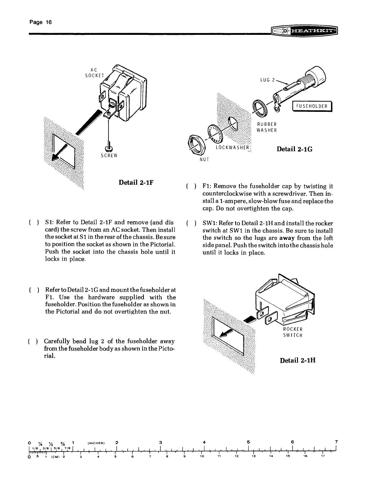
Detail 2-1F
( )
Sl:
Refer to Detail 2-1F
and
remove (and dis
card)
the
screw from an
AC
socket.
Then
install
the
socketatS1
in
the
rear ofthe chassis.
Be
sure
to position
the
socket as
shown
in
the
Pictorial.
Push
the
socket
into
the
chassis hole
until
it
locks
in
place.
( ) RefertoDetail2-1G
and
mount
the
fuseholder at
Flo
Use
the
hardware
supplied
with
the
fuseholder. Position
the
fuseholder as
shown
in
the
Pictorial
and
do
not
overtighten
the
nut.
( ) Carefully bend lug 2 of
the
fuseholder away
from
the
fuseholder
body
as
shown
in
the
Picto-
rial.
o
'l4
'h
3;"
1
(INCHES)
l'
(8
I
3(8
I
5(8
I 7
(8
I
'I
I I I I '
2
I
'I
I ,
, I I I I
"Ii,
II
i
'i
ii'
o 5 1
(CM)
2 3 4 5 6 8 9
FUSEHOLDER
LOCKWASHER:
.,',
Detail2-1G
NUT
( )
Fl:
Remove the fuseholder cap
by
twisting it
counterclockwise
with
a screwdriver,
Then
in-
stall a
i-ampere.
slow-blowfuse
and
replace
the
cap. Do
not
overtighten
the
cap.
( ) SW1: Refer to Detail2-1H
and
install the rocker
switch at
SWl
in
the
chassis. Be sure to install
the switch so
the
lugs are
away
from
the
left
sidepanel.
Push
the
switch
into
the
chassishole
until
it
locks
in
place.
4
I I
,
10
ROCKER
SW
ITCH
Detail 2-1H
5 6
I ' I I I
"I
I
I,
I I I I I I
I I I 1 I ,
11
12
13
14
15
16
I
I'
17
7
I

=:
ill
Detail2-2A
Refer to Pictorial 2-2 (Illustration Booklet,
Page
4)
for
the
following steps.
( ) Refer
to
Detail2-2A
and
prepare
the
line
cord
as
follows:
1.
Remove
the
outer
insulation
of
the
line
cord
for
2".
2.
Twist
together
the
fine
wire
strands
at
the
end
of
each
lead.
Then
melt
a
small
amount
of
solder
to
the
end
of each
lead
to
hold
the
strands
together.
NOTES:
1.
When
you
are
directed
to
"make
a
mechanically
secure
connection,"
as
in
the
following steps,
refer
to
the
inset
drawing
on
the
Pictorial.
2. In
the
following steps, (NS)
means
not
to
solder
because
other
wires
will
be
added
later.
"S-"
with
a
number
following it,
such
as (S-3),
means
to
solder
the
connection.
The
number
following
the
"S-"
tells
you
how
many
wires are at
the
connection.
( ) Route
the
end
ofthe
line
cord
through
hole
AJ
in
the
chassis.
Then
connect
the
green
line
cord
lead
to solder
lug
AE (S-l). Make a
mechani-
cally
secure
connection.
( )
Connectthe
black
line
cord
lead
toAC
socket
Sl
lug 1 (NS).
Make
a
mechanically
secure
connec-
tion.
PLACE
THE
LI
NE
CORD
IN
THE
SLOT.
SQUEEZE
THE
TWO
SEGMENTS
TOGETHER.
Detail 2-2B
Page
17
INSERT
THE
REAR
HALF
I
NTO
THE
HOLE.
( )
Connect
the
white
line
cord
lead
to
AC socket
Sllug
2 (NS). Make a
mechanically
secure
con-
nection.
( ) Install
the
strain
relief
on
the
line
cord
at
AJ
as
shown
in
Detail 2-2B.
( )
Cl:
Cut
both
leads
of a .001
/-tF
(1000 pF)
ceramic
capacitor to 1/2".
Then
connect
the
capacitor
between
AC socket
Sllugs
1 (NS)
and
2 (NS). Make
mechanically
secure
connections.
NOTE:
When
wiring
this
kit,
you
will
be
directed
to
prepare
the
wires
ahead
of time, as
in
the
following
step. To
prepare
a wire,
cut
it
to
the
indicated
length
and
remove
1/4" of
insulation
from each
end.
Then
melt
a
small
amount
of
solder
on
the
bare
wire
ends
to
hold
the
fine
wire
strands
together,
if
not
already
done.
The
wires are
listed
in
the
order
in
which
you
will
use
them.
( )
Prepare
the
following
medium
black
wires:
2-1/2"
1-3/4"
1-1/2"
NOTE:
Make mechanically secure connections
when you connect the prepared wires
in
the
next three steps.
l )
Connect
the
2-1/2"
wire
from
solder
lug AF (S-l)
to
AC socket
Sl
lug
3 (S-l).
( )
Connect
the
1-3/4"
wire
from AC socket
Sllug
1
(S-3) to
fuseholder
Fl
lug
1 (S-l).
( )
Connect
the
1-1/2"
wire
from
fuseholder
Fllug
2 (S-l)
to
switch
SWl
lug
1 (S-l).

Page 18
Refer to Pictorial 2-3 for
the
following steps.
( ) SW2: Locate
the
120/240
slide
switch
(#60-54)
and
position
it
as
shown
in
the
Pictorial. (Note
the
position
of
the
bare
jumper
wire
connected
between
lugs 5
and
6
on
the
switch.)
( )
Prepare
the
following
medium
black
wires:
One
5/1
One
4/1
Two
1-1/2"
NOTE:
Make
mechanically
secure
connections
when
you
connect
the
wires
to
the
switches
in
the
following
steps.
( ) Connect
one
end
of
the
5/1
black wire
to
switch
SW2 lug 1 (NS).
The
other
end
will
be
con-
nected
later.
( )
Connect
one
end
of
the
4"
black
wire
to
switch
SW2
lug
2 (NS).
The
other
end
will
be
con-
nected
later.
( ) Connect
one
end
ofa
1-1/2/1
wire to
switch
SW2
lug 3 (S-l).
The
other
end
will
be
connected
later.
( ) Connect
one
end
of
the
other
1-1/2/1
wire
to
switch
SW2 lug 4 (S-l).
The
other
end
will
be
connected
later.
( ) Locate
the
power
transformer.
Then
slide
a rub-
ber
grommet over
the
black, black-red, black-
green, black-yellow, black-white,
and
black-
gray transformer leads.
( )
Connect
the
black transformer
lead
to
switch
SW2 lug 1
(S-2:).
( )
Connect
the
black-red transformer lead to
switch
SW2 lug 2 (S-2).
( ) SW3: Locate
the
NOR/LOW
slide
switch
(#60-
608)
and
position
it
near
slide
switch
SW2 as
shown.
Refer to
the
printing
on
the
front of
the
switch
and
the
inset
drawing
on
the
Pictorial to
properly
orient
the
switch.
( ) Connect
the
black-white
transformer
lead
to
switch
SW3 lug 5 (S-l).
( ) Connect
the
black-gray transformer lead to
switch
SW3 lug 6 (S-l).
( ) Connect
the
free
end
of
the
black
wire
coming
from
switch
SW2
lug
3
to
switch
SW3
lug
3
(S-l).
( ) Connect
the
free
end
of
the
black
wire
coming
from
switch
SW2 lug 4 to
switch
SW3 lug 4
(S-l).
( )
Connect
the
black-green transformer
lead
to
switch
SW3 lug 1 (S-l).
( )
Connect
the
black-yellow transformer
lead
to
switch
SW3 lug 2 (S-l).

POW
ER
TRANSFORMER
PICTORIAL 2-3
INS:f\
I~B
(})
Page
19
Page 20
___________________________________________________________________
~
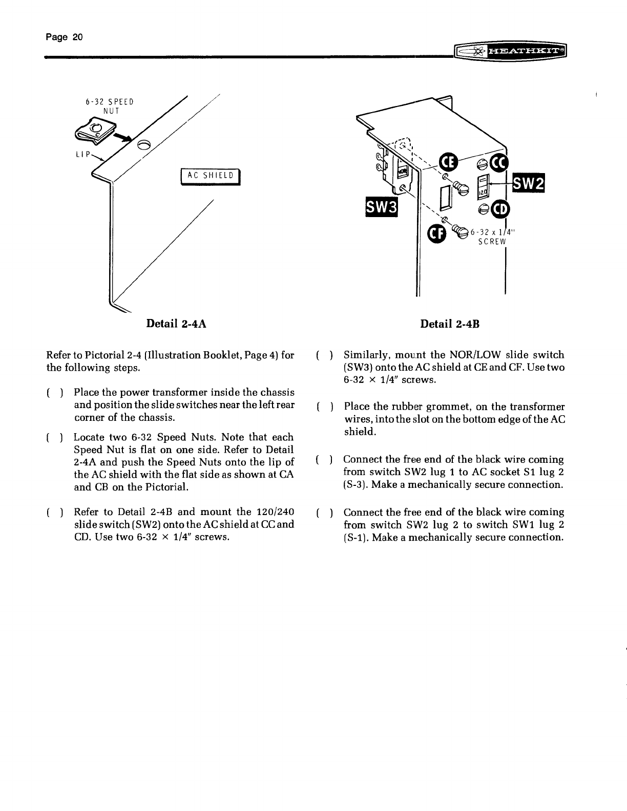
~fif&6Siifii*~
6-32 5
PEED
NUT
IACSHIELDI
Detail
2-4A
Refer to Pictorial
2-4
(Illustration Booklet, Page
4)
for
the
following steps.
( ) Place
the
power transformer
inside
the
chassis
and
position
the
slideswitches near
the
leftrear
corner of the chassis.
( ) Locate two 6-32 Speed Nuts. Note
that
each
Speed Nut is flat
on
one
side. Refer to Detail
2-4A
and
push
the
Speed
Nuts onto
the
lip of
the
AC
shield
with
the
flat side as
shown
at
CA
and
CB
on
the
Pictorial.
( ) Refer to Detail 2-4B
and
mount
the
120/240
slideswitch(SW2) onto
the
AC
shieldat
CC
and
CD.
Use two 6-32 x 1/4" screws.
Detail2-4B
( ) Similarly,
mount
the
NOR/LOW slide switch
(SW3) onto
the
AC
shield
at
CE
and
CF.
Use two
6-32 x 1/4" screws.
( ) Place
the
rubber grommet, on
the
transformer
wires,
into
the
slot on thebottom edge of
the
AC
shield.
( ) Connect
the
free
end
of
the
black wire coming
from switch SW2 lug 1 to
AC
socket
Sl
lug 2
(S-3). Make a mechanically secure connection.
( ) Connect
the
free
end
of
the
black wire coming
from switch SW2 lug 2 to switch
SW1
lug 2
(S-l). Make a mechanically secure connection.
Table of contents
Other Heath Company Desktop manuals


