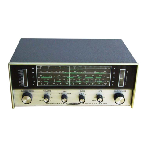
Heathkit UXR-1 User manual

INTRODUCTION
The
Model
UXR-1
is
a
six
transistor
superheterodyne
receiver
of
advanced
design
using
the
latest
prin-
ted
circuit
techniques
to
ensure
the
utmost
reliability,
consistency
and
ease
of
assembly.
Both
the
medium
and
long
wave
bands
are
covered
and
the
extra
large
7!
x
4"!
high
flux
speaker
will
give
ex-
cellent
tone
and
volume.
which
will
give
many
years
of
service
and
the
controls
are
fabric.
The
extremely
attractive
case
is
made
of
first
grade
hard
wearing
leather
gold
trimmed
matching
the
elegant
speaker
SPECIFICATIONS
Tuning
Range
ee
.
Sensitivity
.......
eee
ee
Loud
speaker
.4.466w
eae
«
Ya
ee
ewe
ees
Batlle
rye
gaa
ae
Sas
Battery
Nite
tiacsie
eso
see
ee
we
TETAN
SISOS
steel
Leak
bes
Aiea
te
ersle
es
See
he
Peni
ss
ee
eid
Printed
Board
CaS
Ceci
he
eco
ecu
Apa
ean
Aiea
Aetna
cated,
eed
ee
Pave
Ge
ha
ae
ad
ee
rh
gem
Weight
with
battery
..
ee
ee
oe
Shipping
weight
ee
]
GLOUCESTER
DAYSTROM
-
5
lbs.
200-550
metres
(1500-535
kc/s.)
1000-1875
metres
(300-160
kc/s.)
15
pV
for
50
mW
output.
x
4"
High
flux,
wide
angle
diffusion.
.
Drydex
DT9,
Ever
Ready
PP9.
300-400
hours
average
use.
.
Mullard
I
-
OC44,
2
-
OC45,
1
-
OC8ID
and
2
-
OC81
plus
|!
-
OA81
Diode.
.
Standard
E.
17148
High
Grade
Electrical
laminate
with
.0015
copper
foil.
.
Solid
cowhide
leather
throughout.
5
lbs.
8
ozs,
LTD.
ENGLAND

ENGLAND
‘I-adXN
TAGOW
YSAISDSY
YOLSISNVYL
YOS
LINDYID
fa)
=
nal
2
O
ce
-
—)
>=
<
O
ed
ab
|
SLIOA6
—
wos9
s9cz
VAGE
4995
wa
GLOUCESTER

PRELIMINARY
NOTES
AND
INSTRUCTIONS
The
Step-»y-Step
instructions
given
in
this
manual
should
be
followed
implicitly
to
ensure
a
minimum
of
difficulty
during
construction
and
a
completely
satisfactory
result,
including
many
years
of
accur-
ate,
trouble-free
service
from
the
finished
instrument.
UNPACK
THE
KIT
CAREFULLY,
EXAMINE
EACH
PART
AND
CHECK
IT
AGAINST
THE
PARTS
LIST.
In
so
doing,
you
will
become
acquainted
with
the
parts.
If
a
shortage
is
found,
attach
the
inspection
slip
to
your
claim
and
notify
us
promptly.
Screws,
nuts
and
washers
are
counted
mechanically
and
if
a
few
are
missing,
please
obtain
them
locally
if
at
all
possible.
Lay
out
all
the
parts-so
that
they
are
readily
available
in
convenient
categories.
Refer
to
the
general
information
inside
the
covers
of
this
manual
for
instructions
on
how
to
identify
components.
Moulded
egg
containers
make
handy
trays
for
holding
small
parts.
Resistors
and
Capacitors
may
be
placed
in
the
edge
of
a
corrugated
cardboard
box
until
they
are
needed.
Use
lockwashers
under
all
screws
and
nuts,
and
also
between
controls
and
the
chassis.
When
solder
lugs
are
mounted
under
nuts,
the
use
of
lockwashers
is
unnecessary.
-
Resistors
and
capacitors
have
a
tolerance
rating
of
*
10%
unless
otherwise
stated.
Therefore
a
100K
ohm
resistor
may
test
anywhere
between
90
and
110K
ohms.
Frequently
capacitors
show
an
even
greater
variation
suchas
-50%to
+100%.
This
Heathkit
accommodates
such
variations.
Unless
otherwise
stated
all
wire
used
is
insulated.
Bare
wire
is
only
used
where
lead
lengths
are
short
and
there
is
no
possibility
of
a
short-circuit.
Wherever
there
is
a
possibility
of
the
bare
wire
leads
of
resistors
or
capacitors,
etc.,
shorting
to
other
parts
or
to
chassis,
such
leads
must
be
cov-
ered
with
insulated
sleeving.
To
facilitate
describing
the
location
of
parts,
all
valveholders,
controls,
tag
strips,
etc.,
have
been
lettered
or
numbered.
Where
necessary
all
such
coding
is
clearly
shown
in
the
illustrations.
When
instructions
say,
for
example,
''wire
to
socket
G3".
refer
to
the
proper
figure
and
connect
a
wire
to
tag
3
of
socket
G.
All
rotary
switch
tags
are
numbered
clockwise
when
viewed
from
the
rear
of
the
wafer,
i.e.
the
end
remote
from
the
knob.
All
resistors
may
be
wired
either
way
round.
All
capacitors,
excepting
electrolytic
capacitors,
may
be
wired
either
way
round.
Carefully
letter
and
number
tag
strips,
valveholders,
transformers,
etc.
A
wax
pencil
is
ideal
for
this
purpose.
When
mounting
resistors
and
capacitors
make
sure
that
the
value
can
be
read
when
in
position.
Observe
polarity
on
all
alectrolytic
capacitors,
i.e.
RED
=
POSITIVE.
Where
connections
to
the
''Busbar"
are
referred
to
in
the
Step-by-Step
instructions,
the
connections
should
be
made
to
the
nearest
point.
A
circuit
description
is
included
in
this
manual
so
that
those
with
some
knowledge
of
electronics
will
be
able
to
obtain
a
clearer
picture
of
the
actual
functioning
of
this
instrument.
It
is
not
expected
that
those
with
little
experience
will
understand
the
description
completely,
but
it
should
be
of
help
in
the
event
that
they
desire
to
become
more
familiar
with
the
circuit
operation
and
thus
learn
more
from
GLOUCESTER
DAYSTROM
LTD.
ENGLAND

building
the
kit
than
just
the
placing
of
parts
and
the
wiring.
Read
this
manual
right
through
before
starting
actual
construction.
In
this
way,
you
will
become
fam-
iliar
with
the
general
step-by-step
procedure
used.
Study
the
pictorials
and
diagrams
to
get
acquainted
with
the
circuit
layout
and
location
of
parts.
When
actually
assembling
and
wiring,
READ
THROUGH
THE
WHOLE
OF
EACH
STEP
so
that
no
point
will
be
missed.
A
tick
(Teneara
be
made
in
the
space
provided
at
the
beginning
of
each
instruction
immediately
it
has
been
completed.
This
is
most
important
as
it
will
avoid
omissions
or
errors,
especially
whenever
work
is
interrupted
in
the
course
of
construction.
Some
Kit-builders
have
found
it
helpful
in
addition
to
mark
each
lead
in
the
pictorial
in
coloured
pencil
as
it
is
completed.
Successful
instrument
construction
requires
close
observance
of
the
step-by-step
procedure
outlined
in
this
manual.
For
your
convenience,
some
illustrations
may
appear
in
large
size
folded
sheets.
It
is
suggested
that
these
sheets
be
fastened
to
the
wall
over
your
work
area
for
reference
purposes
during
instrument
construction.
The
Company
reserves
the
right
to
make
such
circuit
modifications
and/or
component
substitutions
as
may
be
found
desirable,
indication
being
by
''Advice
of
Change"
included
in
the
Kit.
NOTE:
Daystrom
Ltd.
will
not
accept
any
responsibility
or
liability
for
any
damage
or
personal
injury
sustained
during
the
building,
testing,
or
operation
of
this
instrument.
ALL
GUARANTEES
ARE
VOIDED
AND
WE
WILL
NOT
REPAIR
OR
SERVICE
INSTRUMENTS
IN
WHICH
ACID
CORE
SOLDER
OR
PASTE
FLUXES
HAVE
BEEN
USED.
WHEN
IN
DOUBT
ABOUT
SOLDER,
IT
IS
RECOMMENDED
THAT
ONLY
'"'60/40''
RESIN
CORE
RADIO
SOLDER
BE
PURCHASED.
PROPER
SOLDERING
PROCEDURE
Only
a
small
percentage
of
Heathkit
purchasers
find
it
necessary
to
return
an
instrument
for
factory
service.
Of
these,
by
farthe
largest
proportion
function
improperly
due
to
poor
or
improper
soldering.
Correct
soldering
technique
is
extremely
important.
Good
soldered
joints
are
essential
if
the
perform-
ance
engineered
into
the
kit
is
to
be
fully
realised.
If
you
are
a
beginner
with
no
experience
in
solder-
ing,
half
an
hour's
practice
with
odd
lengths
of
wire
and
a
valveholder,
etc.,
will
be
invaluable.
Highest
quality
resin-cored
solder
is
essential
for
efficiently
securing
this
kit's
wiring
and
components.
The
resin
core
acts
as
a
flux
or
cleaning
agent
during
the
soldering
operation.
NO
SEPARATE
FLUX
OR
PASTE
OF
ANY
KIND
SHOULD
BE
USED.
We
specifically
caution
against
the
use
of
so-called
"non-corrosive"
pastes
or
liquids.
Such
compounds,
although
not
corrosive
at
room
temperatures,
will
form
residues
when
heated.
These
residues
are
deposited
on
surrounding
surfaces
and
attract
moisture.
The
resulting
compounds
are
not
only
corrosive
but
actually
destroy
the
insulation
value
of
non-conductors.
Dust
and
dirt
will
tend
to
accumulate
on
these
"bridges"
and
eventually
will
cause
erratic
or
degraded
performance
of
the
instrument.
IMPORTANT
IN
THE
"STEP-BY-STEP"
PROCEDURE
the
abbreviation
''NS"
indicates
that
the
connection
shouldnot
yet
be
soldered,
for
other
wires
will
be
added.
Ata
later
stage
the
letter
'S"
indicates
that
the
con-
nection
must
now
be
soldered.
Note
that
a
number
appears
after
each
solder
(S)
instruction.
This
number
indicates
the
number
of
leads
connected
to
the
terminal
in
question.
For
example,
if
the
in-
structions
read,
'Connect
one
lead
of
a
47
K
ohm
resistor
to
tag
1
(S-2)",
it
will
be
understood
that
there
should
be
two
leads
connected
to
the
terminal
at
the
time
it
is
soldered.
This
additional
check
will
help
to
avoid
errors.
When
two
or
more
connections
are
made
to
the
same
solder
tag
a
common
mistake
is
to
neglect
to
solder
the
connections
on
the
bottom.
Make
sure
all
the
wires
are
soldered.
GLOUCESTER
-DAYSTROM
LTD.
ENGLAND

BEND
LEAD
CLOSE
TO
BODY
=
=
=
=
PROPER
MOUNTING
ul
UA
3”.
SRLEAD
ONLY
|
|
NE
erereeS
TD
—_
f
Fal
S
_
SOLDER
on
PROPER
SOLDER
7
went
af"
ONLY
CONNECTION
.
(MF.
LEAD
WAS
MOVED
SPREAD
LEADS
OF
EACH
COMPONENT
DeapAnvened
TO
KEEP
THEM
FROM
FALLING
OUT
NO
CONNECTION
=
253s,
(NO
LEAD
ee
<
WHEN
THE
BOARD
!1S
TURNED
5
SOLDER
AND
LEAD
BRIDGES
CIRCUIT
BOARD
WIRING
AND
SOLDERING
Before
attempting
any
work
onthe
circuit
board,
read
the
following
instructions
carefully
and
study
the
figures
shown.
It
isonly
necessary
to
observe
a
few
basic
precautions
which
will
ensure
proper
operation
of
the
unit
the
first
time
it
is
turned
on.
Proper
mounting
of
components
on
the
board
is
essential
for
good
performance,
A
good
general
rule
to
follow
is
that
all
components
on
the
board
should
be
mounted
tightly
to
the
board,
unless
instructions
state
otherwise.
All
leads
should
be
kept
as
short
as
possible
to
minimize
the
effects
of
stray
capacity
in
the
wiring.
Proper
and
im-
proper
methods
of
mounting
are
illustrated
in
the
accompanying
Figures,
Tubular
capacitors
and
resistors
will
fit
properly
if
the
leads
are
bent,
as
shown.
Disc
capacitors
will
generally
fit
inplace
withno
lead
preparationother
than
determining
that
the
leads
are
straight.
Components
with
tags
norm-
ally
require
no
preparation
unless
the
tags
appear
to
be
bent,
in
which
case
they
can
be
straightened
with
a
pair
of
pliers.
Parts
should
be
inserted
as
instructed,
and
the
leads
bent
outward
slightly,
as
illustrated,
to
lock
them
in
place,
Components
will
be
soldered
in
groups:
after
a
group
of
components
have
been
installed,
instructions
will
be
given
to
solder
them.
When
the
components
have
been
soldered,
diagonal
cutters
may
be
used
to
cut
off
the
excess
leads
close
to
the
board.
The
actual
technique
of
soldering
leads
to
a
circuit
board
is
quite
simple.
Position
the
tip
of
the
soldering
iron
so
that
it
firmly
contacts
boththe
ci
rcuit
board
foil
and
the
wire
or
tag
to
be
soldered,
as
shown.
Then
the
solder
should
immediately
be
placed
between
the
iron
and
the
joint
to
be
soldered.
Remove
the
solder
as
soon
as
it
begins
to
melt
and
flow
on
to
the
leadand
foil.
Holdthe
tip
of
the
iron
in
place
only
until
the
solder
begins
to
flow
outward
over
the
foil,
Then
remove
the
iron
quickly.
USE
THE
SMALL
GAUGE
SOLDER
FOR
THE
PRINTED
BOARD,
Avoid
overheating
the
connection.
A
soldering
pencil
or
small
iron
(approximately
30
watts)
is
ideal
for
use
in
cir-
cuit
boardwork.
If
a
higher
wattage
iron
or
soldering
gun
must
be
used,
precautions
must
be
taken
to
avoid
circuit
board
damage
due
to
overheating.
The
use
of
excessive
amounts
of
solder
will
increase
the
possibility
of
bridging
between
foil
conductors
or
plugging
holes
which
are
to
be
left
open
for
wires
which
may
be
added
later
on,
If
solder
is
accidentally
bridged
across
in-
sulating
areas
between
conductors,
it
can
be
cleaned
off
by
heating
the
connection
carefully
and
quickly
wiping
the
solder
away
witha
soft
cloth.
Holes
which
become
plugged
can
be
cleared
by
heating
the
area
immediately
over
the
hole
while
gently
pushing
the
lead
of
a
resistor
through
the
hole
from
the
opposite
side,
and
withdrawing
the
lead
be-
fore
the
solder
rehardens.
Do
not
force
the
wire
through:
too
much
pressure
before
the
solder
has
time
to
soften
may
separate
the
foil
from
the
board,
In
cases
where
foil
does
become
damaged,
repairs
can
usually
be
made
with
little
difficulty.
A
break
in
the
foil
can
be
rejoined
with
a
small
piece
of
bare
wire
soldered
across
the
gap,
or
be-
tween
the
foil
and
the
lead
of
a
component.
GLOUCESTER
DAYSTROM
LTD.
ENGLAND

If
the
tags
are
bright
and
clean
and
wires
free
of
wax,
frayed
insulation
and
other
foreign
substances,
no
difficulty
will
be
experienced
in
soldering.
Crimp
or
otherwise
secure
the
wire
(or
wires)
to
che
terminal,
so
a
good
mechanical
joint
is
made
without
relying
on
solder
for
physical
strength.
1,
CRIMP
WIRES
2.
HEAT
CONNECTION
3.
APPLY
SOLDER
ALLOW
SOLDER
TO
FLOW
COLD
SOLDER
JOINT
PROPER
SOLDERED
COLD
SOLDER
JOINT
CONNECTION
INSUFFICIENTLY
CONNECTION
CONNECTION
MOVED
HEATED
WHILE
COOLING
Typical
good
and
bad
soldered
joints
are
shown
above.
A
poor
soldered
joint
will
usually
be
indicated
by
its
appearance.
The
solder
will
stand
up
in
a
blobon
topof
the
connection,
with
no
evidence
of
flowing
out
caused
by
actual
''wetting'
of
the
contact.
A
crys-
talline
or
grainy
texture
on
the
solder
surface
caused
by
movement
of
the
joint
before
it
solidifies
is
another
evidence
of
a
"cold"
connection
and
possible
"dry
joint".
In
either
event,
reheat
the
joint
until
the
solder
flows
smoothly
over
the
entire
junction,
cooling
toa
smooth,
bright
appearance.
To
make
a
good
soldered
joint,
the
clean
tip
of
the
hot
soldering
iron
should
be
placed
against
the
joint
to
be
soldered
so
that
the
flat
tag
is
heated
sufficiently
to
melt
the
solder.
Resin
core
solder
is
then
placed
against
both
the
tag
and
the
tip
of
the
iron
and
should
immediately
flow
over
the
joint.
See
ill-
ustrations.
Use
only
enough
solder
to
cover
the
wires
at
the
junction;
it
is
not
necessary
to
fill
the
entire
hole
in
the
tag
with
solder.
Don't
allow
excess
solder
to
flow
into
valveholder
contacts,
ruining
the
sockets,
or
to
creep
into
switch
sockets
and
destroy
their
spring
action.
Position
the
work
so
that
GLOUCESTER
DAYSTROM
LTD.
ENGLAND

gravity
teuds
to
keep
the
solder
where
you
want
it.
A
clean,
well-tinned
soldering
iron
is
also
important
to
obtain
consistently
perfect
connections.
For
most
wiring,
a
30
to
50
watt
iron,
or
the
equivalent
in
a
soldering
gun,
is
very
satisfactory.
Keep
the
iron
hot
and
its
tip
and
the
connections
to
be
soldered
bright
and
clean.
Always
place
the
solder
on
the
heated
"work"
andthen
place
the
bit
ontop
of
the
solder
until
it
flows
readily
and
''wets"'
the
joint
being
made.
Don't
take
the
solder
on
to
the
bit
and
then
try
to
bring
it
to
the
work
directly
from
the
solder-
ing
iron.
Whenever
possible
a
joint
should
be
secured
mechanically
by
squeezing
tight
with
pliers
prior
to
soldering
it.
The
hot
soldering
bit
should
frequently
be
scraped
clean
with
a
knife,
steel
wool
or
a
file,
or
wiped
clean
quickly
by
means
of
a
rag
or
steel
wool.
Don't
apply
too
much
solder
to
the
soldered
joint.
Don't
apply
the
solder
to
the
iron
only,
expecting
that
it
will
roll
down
onto
the
connection.
Try
to
follow
the
instructions
and
illustrations
as
closely
as
possible,
Don't
bend
a
lead
more
than
once
around
a
connecting
point
before
soldering,
so
that
if
it
should
have
to
come
off
due
to
a
mistake
or
for
maintenance
it
will
be
much
easier
to
remove.
Follow
these
instructions
and
use
reasonable
care
during
assembly
of
the
kit.
This
will
ensure
the
deserved
satisfaction
of
having
the
instrument
operate
perfectly
the
first
time
it
is
switched
on.
toc
N
ER
BSW
locating
hole.
CHASSIS
—
FRONT
VIEW-SHOWING
MOUNTING
OF
SPEAKER
AND
GROMMETS.
PICTORIAL.|I
GLOUCESTER
DAYSTROM
LTD.
ENGLAND

eer
ee
MOUNTING
OF
COMPONENTS
TO
METAL
CHASSIS
SEE
PICTORIAL
2A
Place
chassis
(Part
No,
200-102B)
on
your
workbench
as
shown
in
Pictorial
2A.
Mount
the
aerial
socket
to
chassis
at
position
SK
using
2
-
6BA
x
="
screws
with
lockwashers
and
nuts.
Mount
the
control
panel
(Part
No.
200-501B)tochassis
using
4
-
6BA
x
<''
screws
with
lockwashers
and
nuts,
Mount
the
volume
control
at
location
A.
Insert
3
small
grommets
in
the
holes
around
the
large
hole
at
location
C.
See
Pictorial
l,
Mount
the
two-gang
capacitors
at
location
C
using
3
-
4BA
x
3/8''
screws,
flat
and
lockwashers.
Tighten
these
screws
so
that
the
ends
just
appear
through
the
tapped
holes.
See
Pictorial
1,
Mount
the
wave-change
switch
at
location
BSW
using
the
location
hole
as
shown.
Bend
all
tags
outward
as
shown
in
Pictorial
2A,
This
is
to
allow
clearance
for
components
on
circuit
board
to
be
added
later,
Mount
a
4BA
solder
tag
at
location
H2
using
1
-
4BA
x
3/8"
screw
with
lockwasher
and
nut,
Mount
a
l-way
tagstrip
(with
one
earth
tag)
at
location
J
using
1
-
4BA
x
3/8''
screw
with
lock-
washer
and
nut,
Mount
the
large
transformer
at
location
TLS
using
2
-
4BA
x
3/8"
screws
with
lockwashers
and
nuts,
Mount
the
eliptical
loudspeaker
using
4
-
4BA
x
3/8''
screws
with
lockwashers
and
nuts,
See
Pic-
torial
I,
Mount
a
2-way
tagstrip
at
location
M
using
1
-
4BA
x
3/8"
screw
with
lockwasher
and
nut,
Mount
a
3-way
tagstrip
at
location
Y
using
1
-
4BA
x
3/8''
screw
with
lockwasher
and
nut,
Insert
the
two
large
grommets
at
locations
DF
and
EF.
Mount
the
ferrite
rod
aerial
through
grommets
DF
and
EF.
First
inserting
the
LW
end
through
grommet
DF
for
approximately
1",
Then
partly
withdraw
and
insert
the
other
end
through
grom-
BP.
Finally
adjust
the
ferrite
rod
centrally
with
the
BLACK
tags
facing
the
chassis
rear.
CHASSIS
WIRING
-
SEE
PICTORIAL
2B
Note:
Where
coloured
insulated
wire
is
used,
strip
back
the
insulation
q''
at
each
end
before
connecting,
(
(
)
)
Connect
a
2"'
length
of
BLACK
wire
between
tag
2
of
the
AE
coil
(S-1)
to
the
BLACK
tag
LW
(NS).
Connect
a
10"
length
of
BLACK
wire
between
tag
1
of
the
AE
coil
(S-1)
to
the
aerial
socket
SK
(S-1).
Route
as
shown.
Connect
a
3"!
length
of
BLACK
wire
between
BSW2
(NS)
and
BSW7
(S-1).
Dress
against
panel
as
shown.
Connect
a
bare
wire
link
between
BSW5
(NS),
BSW4
(S-1)
and
BSW-PI1
(S-1).
Connect
a
6"
length
of
RED
wire
between
BSW-P2
(S-1)
and
MI
(NS).
Connect
a
33''
length
of
ORANGE
wire
between
BSW10
(S-1)
and
the
ORANGE
tag
LW.
(Right-hand)
coil
on
ferrite
rod.)
(S-1).
Connect
a
35"
length
of
RED
wire
between
BSW2
(S-2)
and
the
RED
tag
LW.
(Right-hand
coil
on
ferrite
rod.)
(S-1).
Connect
a
33"length
of
GREEN
wire
between
BSW8(S-1)
and
the
GREEN
tag
MW.
(Left-hand
coil
on
ferrite
rod.)
(S-1),
GLOUCESTER
DAYSTROM
LTD.
ENGLAND

ees
72+}
/it
See
NOTE-TAGS
3,6,9,
&
12
ARE
NOT
USED
ON
SWITCH
BSW.
be
MO
Ea)
puma
a
Cit
ETT
AET
ES:
Ny
ef
MOUNTING
OF
COMPONENTS
TO
METAL
CHASSIS.
PICTORIAL
2A,
GLOUCESTER
DAYSTROM
LTD.
Biappa

i,
anaes
a
iP
AG
UCC
A
_
Ee
=a
Vs
:
“
—
——
bh
4
CHASSIS
WIRING
PICTORIAL
2B.
DAYSTROM
LTD.
]iuuuuaibestibes
GLOUCESTER

Connect
11
a
33"
length
of
YELLOW
wire
between
BSW11
(S-1)
and
the
YELLOW
tag
MW.
(Left-hand
coil
on
ferrite
rod.)
(S-1).
Connect
Connect
Connect
Connect
Connect
Connect
Connect
Connect
Connect
Connect
Connect
Connect
Connect
a
5"
length
of
RED
wire
between
Cl
(S-1)
and
BSW-P3
(S-1).
a
33"
length
of
BLACK
wire
between
BLACK
tag
LW
(S-1)
and
BLACK
tag
MW
(NS).
a
3"
length
of
BLACK
wire
between
H2
(NS)
and
BSW5
(S-2).
Route
as
shown,
a
3"
length
of
BLACK
wire
between
H2
(NS)
and
the
BLACK
tag
MW
(S-2).
a
4"
length
of
BLACK
wire
between
C3
(S-1)
and
H2
(S-3).
a
13"
length
of
BLACK
wire
between
Al
(S-1)
and
J1
(NS).
a1
KQ
resistor
(BROWN,
BLACK,
RED)
between
A2
(S-1)
and
J2
(NS).
the
GREEN
wire
from
transformer
TLS
to
the
loudspeaker
tag
2
(NS).
a
53''
length
of
BLACK
wire
between
the
loudspeaker
tag
2
(S-2)
and
tagstrip
Jl
(S-2).
the
YELLOW
wire
from
transformer
TLS
to
the
loudspeaker
tag
1
(NS).
the
BROWN
wire
from
transformer
TLS
to
tagstrip
M2
(NS).
the
RED
wire
from
transformer
TLS
to
3-way
tagstrip
Y1
(NS).
the
BLACK
wire
from
transformer
TLS
to
Y3
(NS).
Connecta
.25
yF
capacitor
between
Y3
(NS)
andthe
centre
tag
and
a
1002
resistor
(BROWN,
BLACK,
BROWN)
between
Y1
(NS)
and
the
centre
tag
(S-2).
MOUNTING
OF
COMPONENTS
TO
CIRCUIT
BOARD
SEE
PICTORIAL
3
Resistors
and
other
components:
IMPORTANT:
When
mounting
components
to
the
circuit
board
MAKE
SURE
THAT
THE
WIRE
LEADS
ARE
REALLY
CLEAN
and
that
eachcomponent
sits
as
closely
as
possible
to
the
board
before
solder-
Bend
wires
to
suit
location
holes,
Carefully
examine
each
joint
after
soldering
referring
to
Figure
1
and
Page
6
for
examples
of
good
and
bad
soldering.
ing.
Do
not
solder
any
resistors
until
told
to
do
so,
(
(
)
Connect
a
10
KQ
resistor
(BROWN,
BLACK,
ORANGE)
on
the
left-hand
side
of
circuit
board,
)
)
)
)
Connect
Connect
Connect
Connect
Connect
Connect
Connect
Connect
a
56
KQ
resistor
(GREEN,
BLUE,
ORANGE),
a
68
KQ
resistor
(BLUE,
GREY,
ORANGE),
CIRCUIT
an
8,2
KQ
resistor
(GREY,
RED,
RED).
ta
en
vay
-
a
Sat
a2
a
2
.
H
|
Ze
a
1,2
KQ
resistor
(BROWN,
RED,
RED).
ae
|
||
ae
|
||
ae
RESISTOR.
RESISTOR.
a
6802
resistor
(BLUE,
GREY,
BROWN).
GOOD,
BAD.
FIGURE-I.
a
4,7
KQ
resistor
(YELLOW,
VIOLET,
RED),
a
22
KQ
resistor
(RED,
RED,
ORANGE).
a
3.9
KQ
resistor
(ORANGE,
WHITE,
RED).
GLOUCESTER
DAYSTROM
LTD.
ENGLAND

aD
=
x
2
Os
gceamae
omennnuaar
S
g
)
|
,
—
co
=
=
eeaeaae
=
|
wo
=
HS.
{39K
1100.28
i~y
aw
=
ae
Se
TONDOOROCGOO
UC
OLOULL
>
a
|
Ww
J
=
“i
=
wo
Ww
>
uw
qa
=
r+
VO
&
2
.
TY)
-
(Y)
Za
—
wW
w
&
=
an
<
dis
—_
w
<<
ad
—7
UO
=
O
of
Ww
Zz.
UO
Ul
cams
tr
O
_
oa
to
Oo
ZY”
x
UV
w
UO
ruk
as
O
>
roa
=2zw
,
‘
=|
.
!
m
-
MOUNTING
OF
COMPONENTS
TO
CIRCUIT
BOARD
TOP
DECK
Pal
GLOUCESTER
———
@oyV.Wiyu
Xo)
Mim
tey
ENGLAND

13
Connect
a
1
KQ
resistor
(BROWN,
BLACK,
RED),
Connect
a
6802
resistor
(BLUE,
GREY,
BROWN).
)
)
(
)
Connect
a
33
KQ
resistor
(ORANGE,
ORANGE,
ORANGE),
)
Connect
a
10
KQ
resistor
(BROWN,
BLACK,
ORANGE).
)
Connect
a
1
KQ
resistor
(BROWN,
BLACK,
RED).
( )
Connect
a
102
resistor
(BROWN,
BLACK,
BLACK).
(
)
Connect
a
3,9
KQ
HIGH
STABILITY
resistor
(value
marked
on
body),
Location
marked
HS
on
circuit
board,
( )
Connect
a
1002
HIGH
STABILITY
resistor
(value
jageiea
on
RESISTOR
AND
body).
CAPACITOR
ASSEMBLY
(
)
Connect
a
4,72
HIGH
STABILITY
resistor
(value
marked
on
FIG.3
body).
(
)
Connect
a
1
KQ
resistor
(BROWN,
BLACK,
RED).
( )
Select
a
3,9
KQ
resistor
(ORANGE,
WHITE,
RED)
anda.ol
uF
capacitor,
Then
solder
together
as
shown
in
Figure
3,
(
)
Connect
the
3.9
KQ
resistor
and
.01
pF
capacitor
to
the
circuit
board.
(
)
Nowcheckall
resistors
now
mountedon
the
circuit
board
for
correct
value
in
the
correct
position,
(
)
Solder
all
resistor
wire
ends
tothe
circuit
board,
Cut
off
all
protruding
wires
as
close
as
possible.
Electrolytic
Capacitors:
Note:
The
mounting
of
all
electrolytic
capacitors
will
now
be
described.
OBSERVE
POLARITY,
i.e.
RED
end
to
position
indicated
+,
(
)
Connect
a
50
pF
capacitor,
(
)
Connect
a
50
pF
capacitor,
( )
Connect
a
50
pF
capacitor,
(
)
Connect
an
8
pF
capacitor,
Paper
Capacitors:
(
)
Connect
the
4
-
,04
pF
capacitors
to
the
positions
shown.
(
)
Connect
the
.05
pF
capacitor
to
the
position
shown,
(
)
Connect
the
.25
pF
capacitor
to
the
position
shown,
Silver
Mica
Capacitors:
(
)
Connect
a
330
pF
capacitor.
(
)
Connect
a
56
pF
capacitor,
( )
Connect
a
27
pF
capacitor.
( )
Solder
all
capacitor
wire
ends
the
the
circuit
board,
Cut
offall
protruding
wires
as
close
as
possible,
GLOUCESTER
DAYSTROM
LTD.
ENGLAND

14
MOUNTING
OF
SPILLS
(
)
Insert
the
19
soldering
spills
(short
ends)
at
locations
E,
B,
C
and
P
and
squeeze
them
to
retain
until
soldered.
(
)
Now
solder
each
of
the
19
spills.
MOUNTING
OF
COIL
AND
TRANSFORMERS
(
)
Mount
an
IF
transformer
(WHITE
spot)
(solder
each
tag).
(
)
Mount
an
IF
transformer
(WHITE
spot)
(solder
each
tag).
GREEN
SPOT
(
)
Mount
an
IF
transformer
(BLUE
spot)
(solder
each
tag).
“
a
OO
(
)
Mount
the
oscillator
coil
(GREEN
spot).
The
GREEN
spot
©
O10
O
on
the
coil
BASE
must
face
the
GREEN
spot
on
the
top
of
(oxo)
the
circuit
board
(solder
each
tag),
See
Figure
4.
BASE
OF
OSCILLATOR
‘CIRCUIT
( )
Mount
the
driver
transformer
TD,
solder
and
cut
off
sur-
eo
otour
BOARD.
plus
wire
from
all
transformers,
FIG.4
,
(
)
Mountthe
crystal
detector
D1],
position
RED
end+as
shown,
Now
solder
and
trim
wire
ends.
(
)
Strip
back
the
insulation
1"
at
each
end
of
a
23"
and
1$"
length
of
BLACK
wire.
( )
Refer
to
Pictorial
4
and
an
unoccupied
hole
will
be
found
near
each
IF
transformer
can,
(
)
Fromthé
hole
near
the
blue
transformer
take
the
25"
long
insulated
wire
link
to
the
hole
near
the
adjacent
white
transformer.
(
)
Take
the
13"
long
insulated
wire
link
from
the
same
white
transformer
to
the
other
white
trans-
former,
(
)
Solder
all
three
points.
EXTERNAL
WIRING
FROM
CIRCUIT
BOARD
( )
Connect
oneendof
a
5"
length
of
GREEN
wire
to
location
GW
(S-1).
Remove
1"
of
insulation
from
other
end.
Connect
one
end
of
a
5"
length
of
BLUE
wire
to
location
BLW
(S-1).
8
(
)
Connect
one
end
of
a
4"
length
of
YELLOW
wire
to
location
YW
(S-1).
(
)
Connect
one
end
of
a
4"
length
of
RED
wire
to
location
RW
(S-1).
(
)
Connect
one
end
of
a
43"!
length
of
WHITE
wire
to
location
WHW
(S-1).
Connect
one
end
of
a
5''
length
of
BLACK
wire
to
location
BW
(S-1).
&
(
)
Connect
one
end
of
a
5"
length
of
ORANGE
wire
to
location
OW
(S-1).
Connect
one
end
of
a
4''
length
of
BROWN
wire
to
location
BRW
(S-1).
&
(
)
Connect
one
end
of
a
6"
length
of
GREY
wire
to
location
GWY
(S-1).
(
)
Connecta
YELLOW
wire
link
between
location
X
and
Z
on
the
metal
foil
side
of
the
circuit
board.
(See
Pictorial
4.)
GLOUCESTER
DAYSTROM
LTD.
ENGLAND

ENGLAND
CQ
QWwite
=
a)
-
oxal
2.
O
o
-
—)
>
<
Q
SHOWING
METAL
SIDE
OF
CIRCUIT
BOARD
WITH
WIRE
LINK.
PICTORIAL
4
GLOUCESTER

Ia
LT
a
fe
|
—————
or
li
4
}
BATTERY
WIRING
AND
FIXING
OF
CIRCUIT
BOARD
TO
CHASSIS.
PICTORIAL.
2C.
GLOUCESTER
DAYSTROM
LTD.
]iasuueeeiiiioutaDe

WIRING
OF
TRANSISTORS
TO
CIRCUIT
BOARD
17
Note:
Important,
Refer
to
the
block
diagram
for
transistor
type
reference.
A
RED
or
WHITE
spot
is
marked
at
the
wire
end
of
each
transistor,
dicated
on
the
circuit
board,
The
wire
nearest
this
spot
must
be
connected
to
C
in-
Connect
the
other
two
wires
to
Band
E.
As
TR5
and
TR6
will
subse-
quently
be
clamped
to
the
chassis,
ensure
that
no
more
than
3/16"
of
each
lead
is
inserted
into
the
spill
before
soldering.
This
will
avoid
undue
strain
on
the
leads
when
securing
the
heat
sink
clips.
(
(
(
)
Select
the
6
transistors
and
cut
each
wire
lead
to
7/8".
)
Cut
the
length
of
sleeving
into
18
-
3/8''
lengths.
)
Place
a
3/8"
length
of
sleeving
over
each
transistor
lead,
)
Bend
the
wires
of
each
transistor
to
form
a
hook
at
the
ends,
see
Figure
5,
)
Connect
the
3
wires
of
TRI
to
the
spills
C,
B
and
E
(solder
each
wire).
)
Connect
the
3wires
of
TR2
to
the
spills
C,
B
and
E
(solder
each
wire).
)
Connect
the
3
wires
of
TR3
to
the
spills
C,
BandE
(solder
each
wire).
)
Connect
the
3
wires
of
TR4
to
the
spills
C,
Band
E
(solder
each
wire),
)
Connect
the
3
wires
of
TR5
to
the
spills
C,
B
and
E
(solder
each
wire).
)
Connect
the
3
wires
of
TR6
to
the
spills
C,
Band
E
(solder
each
wire),
FIG.5
)
Select
the
P
shaped
clips
and
slide
one
on
each
transistor
TR5
and
TR6,
position
as
shown,
WIRING
OF
CIRCUIT
BOARD
TO
CHASSIS
SEE
PICTORIAL
2C
)
Position
circuit
board
to
chassis.
Do
not
fix
into
position
yet.
Now
connect
the
coloured
wires
in
the
following
order:
(
(
)
Pass
the
GREEN
wire
through
tag
C2
(tuning
capacitor)
and
solder
at
spill
P
)
Connect
the
BLUE
wire
to
BSW]
(S-1).
)
Connect
the
YELLOW
wire
to
BSW-P4
(S-1).
)
Connect
the
BLACK
wire
to
Y3
(S-3).
)
Connect
the
RED
wire
to
Y1
(S-3).
)
Connect
the
ORANGE
wire
to
J2
(S-2).
)
Connect
the
BROWN
wire
to
A3
(S-1).
)
Connect
the
GREY
wire
to
M2
(NS).
)
Connect
the
WHITE
wire
to
the
loudspeaker,
tag
(S-2).
)
Now
secure
circuit
board
to
chassis
using
4
-
6BA
x
4''
screws
and
washers.
GLOUCESTER
DAYSTROM
LTD.
Now
solder
at
C2.
ENGLAND

18
(
)
Select
the
two
lengths
of
BLACK
and
RED
flexible
wire.
(
)
Connect
the
RED
wire,
one
end
to
the
copper
coloured
battery
connector
(S-1)
as
shown
on
detail
below
and
the
other
end
to
MI
(S-2).
( )
In
a
similar
manner
connect
the
BLACK
wire,
one
end
to
the
other
battery
connector
(S-1)
and
the
other
end
to
M2
(S-3).
(
)
Using
a
6BA
x
¢""
screw,
nut
and
lockwasher,
secure
the
heat
sink
clips
on
the
OC81
transistors
to
chassis,
with
the
nut
on
the
inside,
(
)
Check
the
position
of
all
transistors
against
the
block
diagram.
(_)
Finally
insert
the
battery,
thenthread
the
positioning
strap
and
lock
tight,
using
the
studs
provided.
Do
not
connect
the
RED
and
BLACK
leads
to
the
battery
yet.
TRANSISTOR
TYPES
Circuit
Ref.
Transistor
Type
Spot
Coleus,
Collector
Top
TRI
|
OC44
RED
YELLOW
TR2
|
OC45
RED
ORANGE
Mullard
TR3
OC45
RED
BLUE
Mullard
TR4
|
Oc8s1D
RED
Foe
|
Mullard
.
Mullard
Mullard
"REPLACE
LASTIC
TRANSISTOR.
GLOUCESTER
DAYSTROM.
LTD.
ENGLAND

19
TRANSISTOR
VOLTAGES
EMITTER
COLLECTOR
Important:
Before
connecting
the
supply
leads
to
the
battery
and
switching
on,
re-check
the
connec-
tions
of
all
transistors,
also
the
BLACK
and
RED
leads
to
the
battery.
If
the
battery
connections
are
reversed,
permanent
damage
to
the
transistors
may
result.
If
a
transistor
has
to
be
removed
or
replaced,
a
heat
shunt,
such
as
a
pair
of
pliers,
must
be
used
as
shown
in
Fig.
5.
ADJUSTMENT
PROCEDURE
Temporarily
fit
station
name
dial
over
variable
capacitor
spindle
and
align
centrally
to
front
panel.
Secure
with
adhesive
tape.
Now
slide
tuning
knob
with
pointer
attached
over
the
spindle.
Adjust
pointer
to
the
horizontal
position,
with
the
variable
capacitor
spindle
fully
anti-clockwise.
Double
check
the
installation
of
battery
and
transistors
before
attempting
to
operate
your
UXR-1
Tran-
sistor
Receiver.
Errors
could
cause
non-operation
or
damage
to
the
components
in
the
receiver.
When
reasonably
sure
that
no
errors
exist,
plug
in
the
battery
leads
and
switch
to
the
Medium
wave-
band.
Turn
the
volume
control
fully
clockwise,
and
a
slight
rushing
sound
should
be
heard.
If
no
sound
is
heard,
switch
the
receiver
off
and
refer
to
the
section
''Fault
Finding".
If
operation
appears
normal,
you
may
proceed
with
the
adjustments
required
to
obtain
maximum
performance.
Read
each
step
completely
before
performing
the
operation
described.
STEP
ONE
A.
Turn
BOTH
adjusting
screws
on
the
variable
capacitor
down
tightly
without
forcing.
B.
Loosen
EACH
screw
half
a
turn.
GLOUCESTER
———
@ipy-
wana
vo).
mm
muy
ENGLAND

20
STEP
TWO
ADJUSTING
LF.
TRANSFORMERS
This
procedure
willadjustthe
IF
amplifiers.
A,
Tune
in
any
weak
station,
B.
Using
the
alignmenttool
provided,
care
fully
adjust
the
core
of
T3
(BLUE
spot)
left
or
right
toobtain
maximum
volume.
Now
adjust
the
T2
(WHITE
spot)
and
Tl
(WHITE
spot)
inasimilar
manner,
Re-
peat
the
procedure,
The
I.
F.
transformers
are
aligned
approx-
imately
when
supplied
and
only
small
adjust-
ments
should
be
necessary.
Normal
positions
for
the
cores
are:
blue
spot,
about
1/8''belowthetopofthe
formers
FIG.7
and
both
white
spot
transformer
cores
about
1/16"
above
the
top
of
the
former.
ADJUSTING
OSCILLATOR
TRIMMER
STEP
THREE
This
step
will
adjust
the
oscillator
circuit
so
that
the
dial will
indicate
correctly
the
station
wavelengths.
A.
Set
the
dial
to
any
station
of
known
wavelength
below
300
metres.
B.
Adjust
the
screw
on
the
rear
section
ofthe
tuning
capacitor
until
you
receive
the
required
station,
Another
radio
may
prove
helpful
in
id-
entifying
the
chosen
station,
as
several
stations
will
probably
be
heard
whilst
making
this
adjustment,
GLOUCESTER
DAYSTROM
LTD.
ENGLAND
ay
Table of contents
Other Heathkit Receiver manuals

Heathkit
Heathkit HD-3030 User manual

Heathkit
Heathkit Delux SWL GR-54 Installation instructions

Heathkit
Heathkit SB-300 Installation instructions

Heathkit
Heathkit Q MULTIPLIER User manual

Heathkit
Heathkit GR-64 Installation instructions

Heathkit
Heathkit SB-3000 Installation instructions
Heathkit
Heathkit Heathkit HD-3006 User manual

Heathkit
Heathkit Comanche MR-1 Installation instructions

Heathkit
Heathkit SW-717 User manual

Heathkit
Heathkit RA-1 Guide