Novus NR3700-O/G User manual

Users manual
NR3700-O/G
Revision #:
A
Date:
9-13-16
Page #:
1 of 19
www.novuspower.com
NR3700-O/G
10MHz Frequency Reference, OCXO, GPS/GNSS
Locked Single Channel, Auto-Cal
All information provided herein is the proprietary property of Novus Power Products L.L.C. The
information included may be reproduced without the permission or prior approval of Novus Power
Products L.L.C.for the purpose of operating the Novus equipment.

Users manual
NR3700-O/G
Revision #:
A
Date:
9-13-16
Page #:
2 of 19
www.novuspower.com
Table of Contents
1.0 Overview.................................................................................................................................... 3
2.0 Crystal........................................................................................................................................ 5
3.0 GPS Receiver........................................................................................................................... 11
4.0 Input/Output Connectors/Mechanical ..................................................................................... 12
5.0 Typical Phase Noise ................................................................................................................ 14
6.0 Alerts - Optional Function Relay .......................................................................................... 14
7.0 GPS/GNSS Function ............................................................................................................... 14
8.0 Technical Specification .......................................................................................................... 17
8.1 Performance......................................................................................................................... 17
8.2 Environmental and Mechanical........................................................................................... 17
9.0 LIMITED HARDWARE WARRANTY ................................................................................ 18
10.0 Appendix A –NMEA, Radio Control and Status .................................................................19

Users manual
NR3700-O/G
Revision #:
A
Date:
9-13-16
Page #:
3 of 19
www.novuspower.com
1.0 Overview
The NR3700-O/G is a GPS locked OCXO 10 MHz frequency reference with optional
PPS and RS232. The unit features Auto-Calibration such that the most recent
coefficients to compensate the OCXO for drift due to aging and/or temperature are
stored and applied to the OCXO during GPS loss of lock conditions. These coefficients
are updated after 8 hours of continuous GPS locked state. This effectively eliminates
long-term OCXO changes.
Options: RS232,TCXO, and Ultra Low Phase Noise OCXO
The RS 232 interface provides access to the NMEA-0183 data from the GPS at a baud
rate of 38.4K. The baud rate can be changed through the RS232 port using commands
described in Appendix A (Output Format Section).
The unit operates from power in the voltage range of -60 to +60 Vdc in three power
supply ranges that must be specified at purchase. There is also an AC power adapter
available.
The output is a 10 MHz sinewave at 4.5 dBm (0.38 Vrms). The output is short circuit
and transient protected.
PPS pulse is a LVCMOS signal and is also short and transient protected. The PPS has
an accuracy of 30 ns rms.
The Global Positioning System (GPS) transmits a wealth of data. The information is
routinely used for position and timing. This signal is what is used by all GPS disciplined
oscillators for master timing.
The first part of the process is acquiring the GPS satellites and deriving what is called
the PPS signal. This is a pulse that occurs once a second. Most GPS receivers will
specify an accuracy for the leading edge in the range of ~20 ns rms. Due to
atmospheric conditions, multi-path and other effects, there is considerable jitter on the
pulse. This pulse, with exceptional long-term accuracy of ~E-12, is the starting point for
the GPSDO.
The PPS is used to derive a 10MHz signal. As you can imagine, the algorithms for the
generation of the 10MHz are very sophisticated. You are, in effect, creating a 10MHz
waveform with frequency measured once a second by a waveform which has
considerable jitter.

Users manual
NR3700-O/G
Revision #:
A
Date:
9-13-16
Page #:
4 of 19
www.novuspower.com
To get a useful frequency reference, the jitter (phase noise) of the frequency reference
must be improved. A very low bandwidth phase locked loop is used to lock a high
performance 10 MHz OCXO to the synthesized disciplined 10 MHz. By virtue of having
a very low bandwidth, the high frequency jitter is dramatically reduced. There are
numerous tradeoffs - speed of acquisition, phase error, stability, cost, etc. It is a
complex feedback loop and as such, there are many solutions. Noise on the final
output is also affected by the noise in the system. Noise from power supplies and other
circuits can easily sum with the output signal. Care has been taken throughout the
design to achieve a high quality signal.
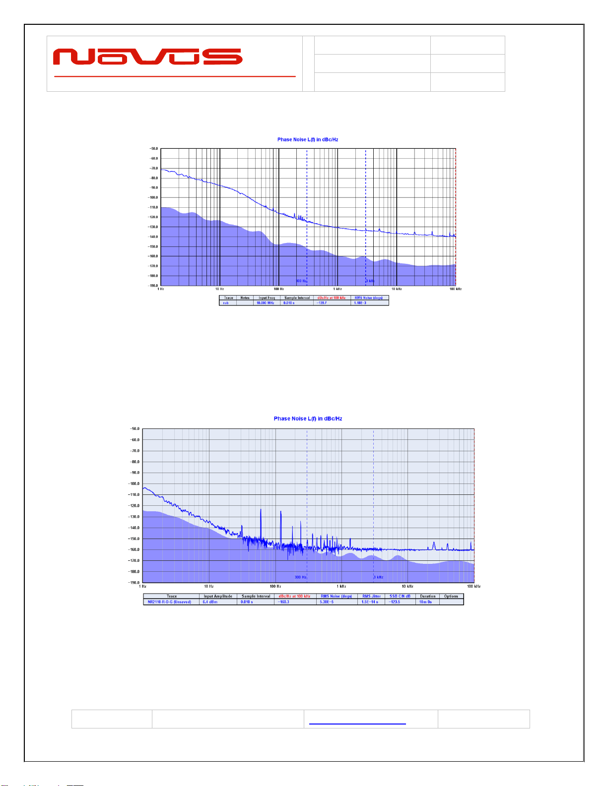
The phase noise of the output is now largely dominated by the voltage controlled
oscillator. The oscillator is typically a crystal oscillator and the quality of that device can
vary significantly. The NR3700-CAL uses an oven-controlled oscillator to provide an
unlocked stability of under 50 ppb/year.
The calibration feature continually monitors the correction coefficients developed
through GPS timing information. These are sampled multiple times per day and stored
in non-volatile memory and in the event of a GPS loss, the saved coefficients are
applied to the TCXO. This effectively eliminates long-term crystal drift.
The NR3700-O/G also incorporates built-in test to monitor critical parameters such as
the TCXO, power supplies and other functions. The built-in test drives a front panel
indicator.
The GPS lock status is also provided by a front panel indicator and a signal accessible
on the front panel DB-9. Many systems will use this signal to detect a long-term GPS
loss-of-lock state which may be caused by an antenna or cabling issue.
The NR3700-O/G draws less than 10 Watts of power from a 12 VDC nominal source.
An AC power adapter is available as an option to allow direct operation from standard
AC power. Also, Novus offers related NR3700 products that can operate anywhere from
–60 to +60 VDC. Contact the factory for further details.

Users manual
NR3700-O/G
Revision #:
A
Date:
9-13-16
Page #:
5 of 19
www.novuspower.com
2.0 Crystal
Novus crystal based frequency reference products are based upon either TCXO or
OCXO technology. Temperature compensated crystal oscillators will normally use an
AT cut crystal and electronically compensate the device with temperature. An OCXO
device uses a SC (stress compensated) crystal and the part is held at a fixed
temperature to minimize temperature drift.
The TCXO implementation results in a temperature stable reference in the single digit
parts per million. An OCXO device affords a reference that is almost 2 orders of
magnitude more stable than the TCXO.
Comparison of an AT versus a SC cut crystal

Users manual
NR3700-O/G
Revision #:
A
Date:
9-13-16
Page #:
6 of 19
www.novuspower.com
Over a broad temperature range, an AT performs very well and much easier to
compensate electronically. It is also a simpler crystal to manufacture than a SC cut
device. For applications where a stability of a few ppm is acceptable, a TCXO can be a
cost effective alternative.
The SC cut results in a much higher Q device and achieves much lower phase noise
than the AT cut. Due to the SC cut being sensitive to pressure and temperature
variation, it is mounted in a temperature controlled hermetic chamber.
OCXO oven temperature is in the range of 90°C. The device heats up and becomes
stable within ~ 5 minutes.
OCXO Frequency Error from cold start
-1.60E+02
-1.40E+02
-1.20E+02
-1.00E+02
-8.00E+01
-6.00E+01
-4.00E+01
-2.00E+01
0.00E+00
2.00E+01
1
11
21
31
41
51
61
71
81
91
101
111
121
131
141
151
161
171
181
191
201
211
221
231
241
Error in Hz
Time in seconds
Frequency Error 1 to 250 seconds

Users manual
NR3700-O/G
Revision #:
A
Date:
9-13-16
Page #:
7 of 19
www.novuspower.com
Typical OCXO
Another alternative for a frequency reference is an atomic reference. These devices use
a change in atomic state of an isotope of Cesium or Rubidium for stability. Instead of a
stability of ±50 ppb/year for a typical OCXO - stability of ±1 ppb/year is very common.
Atomic sources are very complex and while a very stable source, phase noise
performance may not be acceptable for many applications.

Users manual
NR3700-O/G
Revision #:
A
Date:
9-13-16
Page #:
8 of 19
www.novuspower.com
Typical phase noise performance for a Rubidium source
For applications requiring the stability of an atomic source but also requiring low phase
noise, a low phase noise OCXO is disciplined to an atomic source. The phase noise for
the NR2310-R/O has phase noise improved by well over 20 dB by this technique.
Typical Phase Noise Performance-Rubidium with OCXO
When the stability of an atomic or crystal source is not sufficient, a GNSS disciplined
source is an option. A GNSS receiver is installed and timing information from the GNSS

Users manual
NR3700-O/G
Revision #:
A
Date:
9-13-16
Page #:
9 of 19
www.novuspower.com
is used to discipline the timing device. Timing accuracy to a few ppb is readily
achievable.
The GNSS is used to provide timing for a DDS (direct digital waveform synthesizer).
While the DDS has outstanding long-term accuracy, the short-term stability is very poor
due to the nature of the timing source. A GNSS timing source has considerable short-
term instability due to the numerous radio effects-multi-path, signal weakness etc. In
order to develop a stable reference, the GNSS timing waveform is used to discipline a
low noise source with a Kalman filter. A good example of the improved jitter
performance of a Kalman filter is shown below:
Kalman Filter Performance
.

Users manual
NR3700-O/G
Revision #:
A
Date:
9-13-16
Page #:
10 of 19
www.novuspower.com
Typical acceptance testing data for the NR3620-CAL GNSS Locked Reference
Date 1/12/2015 Model
NR3620-CAL
Tech DS Serial 03150565
Count
(second)
Frequency
Actual -
Deviation
(ppb)
Frequency
Unlocked
Actual -
Deviation
(ppb) Unlocked
1.25 1 9999999.998 -0.174 9999999.995 -0.545
1.00 2 9999999.998 -0.198 9999999.994 -0.563
0.99 3 9999999.998 -0.198 9999999.995 -0.543
0.8 4 9999999.998 -0.176 9999999.995 -0.538
59999999.998 -0.163 9999999.994 -0.554
69999999.998 -0.173 9999999.995 -0.546
79999999.998 -0.176 9999999.994 -0.564
89999999.998 -0.223 9999999.995 -0.521
Frequency Specification 9 9999999.998 -0.230 9999999.994 -0.552
10 9999999.998 -0.193 9999999.994 -0.556
Cal Exp
Date
11 9999999.998 -0.212 9999999.995 -0.530
9/8/2015 12 9999999.998 -0.217 9999999.995 -0.529
13 9999999.998 -0.220 9999999.995 -0.507
14 9999999.998 -0.200 9999999.995 -0.526
15 9999999.998 -0.177 9999999.994 -0.553
16 9999999.998 -0.226 9999999.994 -0.563
17 9999999.998 -0.178 9999999.995 -0.527
18 9999999.998 -0.223 9999999.994 -0.565
19 9999999.998 -0.225 9999999.995 -0.537
20 9999999.998 -0.206 9999999.994 -0.568
21 9999999.998 -0.245 9999999.995 -0.524
22 9999999.998 -0.184 9999999.995 -0.526
23 9999999.998 -0.213 9999999.995 -0.546
24 9999999.998 -0.223 9999999.994 -0.551
25 9999999.997 -0.255 9999999.995 -0.502
26 9999999.998 -0.232 9999999.995 -0.549
27 9999999.998 -0.238 9999999.994 -0.587
28 9999999.997 -0.277 9999999.994 -0.568
29 9999999.997 -0.254 9999999.995 -0.516
30 9999999.998 -0.219 9999999.994 -0.561
Hi Limit
Measurenment Hi
Measurement Low
Low limit
Model
Agilent 53230a
Limit ±15ppb
Equipment
Frequency Counter
Frequency Unlocked
Output amplitude
Novus- Reference Group
201 N Forest Ave Suite 225
Independence, MO 64050
866 984 6887
Frequency Locked
Actual
-2.000
-1.500
-1.000
-0.500
0.000
0.500
1.000
1.500
2.000
135791113 15 1719 212325 2729
Deviation ppb
count (seconds)
Frequency Data
-20.000
-15.000
-10.000
-5.000
0.000
5.000
10.000
15.000
20.000
1357911131517192123252729
Deviation ppb
count (seconds)
Frequency Data Unlocked

Users manual
NR3700-O/G
Revision #:
A
Date:
9-13-16
Page #:
11 of 19
www.novuspower.com
3.0 GPS Receiver
The receiver and companion elements generate the GNSS sine wave, PPS and NMEA
serial link. The serial link conforms to NMEA 0183 protocol. The 26 channel high-
sensitivity, high-accuracy Multi-GNSS receiver. Supports TRAIM, GPS, GLONASS,
QZSS, SBAS, Active Anti-Jamming and Advanced Multipath Mitigation Functions.
Typical Antenna Specs:
Frequency Band 1574 –1607 MHz
Antenna Gain 2 dBic @ 90°
Amplifier Gain @ 3.0Vdc: 26dB (typ)
Polarization RHCP
Out-of-band Rejection >60dBc @ f0 ± 50MHz
Impedance 50Ω
VSWR 2.0 Max
DC Input 2.8V - 6V
Noise Figure <2.0dB
Power Consumption 25mA (typ)

Users manual
NR3700-O/G
Revision #:
A
Date:
9-13-16
Page #:
12 of 19
www.novuspower.com
4.0 Input/Output Connectors/Mechanical
All versions of the NR3700 are available in a flanged chassis.
PPS
10 MHz
RS232
Power
Ant
.52
.47
1.82
.70
.48
.50
.37
4.0
3.5
B
.50
.19
O.150
BB
.76
.20
GPS Ant - SMA connects to the GPS ant - provides 3.3 VDC 45ma max
PPS –SMA - one pulse per second (Optional)
10MHz sine –BNC - sine or CMOS output
RS232 - standard NMEA output NMEA-0183
Power - 2 pin Euro / Phoenix type (DigikeyED10546-ND)

Users manual
NR3700-O/G
Revision #:
A
Date:
9-13-16
Page #:
14 of 19
www.novuspower.com
5.0 Typical Phase Noise
10MHz Sine- Primary Output
Offset Frequency (Hz) Typical (dBc / Hz)
10 -95
100 -115
1K -140
10K -145
There are optional phase noise performance levels available - contact factory.
6.0 Alerts - Optional Function Relay
There are a number of critical circuits in the unit. These are monitored and a failure of
any of these will initiate an ALERT condition. The ALERT LED green to red and the
(optional) ALERT relay will open. The normal operating state is the relay contacts will be
closed. During cold start, the oven can behave in such a manner as to give an Oven
alert. This is normal and will only occur from a cold start. This condition should only
exist for approximately five minutes.
Units manufactured after June 1, 2016 move combines the GNSS lock and alert relay to
a single series connection that is routed to the rear connector. When the unit passes
self-test and achieves GNSS lock, the relay closes.
Front Panel LED
GPS Locked / TCXO Loop Locked
GPS Locked / TCXO Loop Unlocked
GPS Tracking / Pending Lock
Alert Status
7.0 GPS/GNSS Function

Users manual
NR3700-O/G
Revision #:
A
Date:
9-13-16
Page #:
15 of 19
www.novuspower.com
The receiver needs to be able to see at least four satellite vehicles (SVs) to obtain an
accurate 3-D position fix. When travelling in a valley, or built-up area, or under heavy
tree cover, you will experience difficulty acquiring and maintaining a coherent satellite
lock. Complete satellite lock may be lost, or only enough satellites (3) tracked to be able
to compute a 2-D position fix, or a poor 3D fix due to insufficient satellite geometry (i.e.
poor DOP). Inside a building or beneath a bridge, it may not be possible to update a
position fix. The receiver can operate in 2-D mode if it goes down to seeing only three
satellites by assuming its height remains constant. But this assumption can lead to very
large errors, especially when a change in height does occur. A 2-D position fix is not
considered a good or accurate fix; it is simply “better than nothing”.
The receiver’s antenna must have a clear view of the sky to acquire satellite lock.
Remember, it is the location of the antenna that will be given as the position fix. If the
antenna is mounted on a vehicle, survey pole, or backpack, allowance for this must be
made when using the solution.
To measure the range from the satellite to the receiver, two criteria are required: signal
transmission time and signal reception time. All GPS satellites have several atomic
clocks that keep precise time and are used to time-tag the message (i.e. code the
transmission time onto the signal) and to control the transmission sequence of the
coded signal. The receiver has an internal clock to precisely identify the arrival time of
the signal. Transit speed of the signal is a known constant (the speed of light),
therefore: time x speed of light = distance.
Once the receiver calculates the range to a satellite, it knows that it lies somewhere on
an imaginary sphere whose radius is equal to this range. If a second satellite is then
found, a second sphere can again be calculated from this range information. The
receiver will now know that it lies somewhere on the circle of points produced where
these two spheres intersect.
When a third satellite is detected and a range determined, a third sphere intersects the
area formed by the other two. This intersection occurs at just two points. A fourth
satellite is then used to synchronize the receiver clock to the satellite clocks.
In practice, just four satellite measurements are sufficient for the receiver to determine a
position, as one of the two points will be totally unreasonable (possibly many kilometers
out into space). This assumes the satellite and receiver timing to be identical. In reality,
when the receiver compares the incoming signal with its own internal copy of the code
and clock, the two will no longer be synchronized. Timing error in the satellite clocks,
the receiver and other anomalies mean that the measurement of the signal transit time
is in error. This, effectively, is a constant for all satellites since each measurement is
made simultaneously on parallel tracking channels. Because of this, the resulting
ranges calculated are known as “pseudo-ranges”.

Users manual
NR3700-O/G
Revision #:
A
Date:
9-13-16
Page #:
16 of 19
www.novuspower.com
To overcome these errors, the receiver then matches or “skews” its own code to
become synchronous with the satellite signal. This is repeated for all satellites in turn,
thus measuring the relative transit times of individual signals. By accurately knowing all
satellite positions, and measuring the signal transit times, the user’s position can be
accurately determined.
The GPS Lock LED illuminates green when the unit is locked to the GPS system. If the
LED is red, the unit is operating on the TCXO.
.
The GPS lock status is on the RS232 connector. After June 1, 2016 the GNSS lock and
status relay is combined and available on the rear panel connector pins 3,4.
If the GPS indicator remains red for an extended period of time, it could be an indication
of an antenna, cabling or unit malfunction. Confirm the antenna is still connected and
has not become obstructed from a clear view of the sky. To check the unit, an alternate
antenna can be tried in order to isolate the malfunction. For further support, please
contact the factory 866-313-9401

Users manual
NR3700-O/G
Revision #:
A
Date:
9-13-16
Page #:
17 of 19
www.novuspower.com
8.0 Technical Specification
8.1 Performance
10MHz Sine
5 +-1 dBm, 50 Ohm - BNC
Harmonics
Less than -30 dBc
Locked Stability
<~E-11 after 100 seconds
RS232 (optional)
NMEA 0183 at full RS232 Levels, default is 38.4K Baud
First Year Frequency Stability
±50 ppb (long-term unlocked)
Temp Stability
±10 ppb
Receiver Sensitivity
-155dBm
PPS (Optional)
30ns RMS accuracy, 3.3 volt logic, output impedance CMOS (±20ma)
Power Requirements
9 to 15 VDC @ 1.0 amps max (10 Watts)
Connectors
BNC - 10 MHz output
SMA - PPS 3.3 VDC CMOS (optional)
2 pin Euro / Phoenix type (DigikeyED10546-ND)
8.2 Environmental and Mechanical
Operating Temperature
0 to 50°C non-condensing (extended temperature range available)
Storage Temperature
-40 to 70°C
Width
3.5” (exclusive of connectors)
Depth
4.0”
Height
1.5”
Weight
~16 oz.

Users manual
NR3700-O/G
Revision #:
A
Date:
9-13-16
Page #:
18 of 19
www.novuspower.com
9.0 LIMITED HARDWARE WARRANTY
Novus Power Products (hereinafter Novus) warrants its products to the original end user (“original purchaser”) and warranty is not
transferrable. Novus guarantees that the NOVUS hardware products that you have purchased from NOVUS are free from defects in materials or
workmanship under normal use during the LIMITED WARRANTY PERIOD. The LIMITED WARRANTY PERIOD starts on the date of
shipment and for the period of 1 (one) year to be free from defects caused by faulty materials or poor workmanship, provided:
(a) NOVUS is notified in writing by Buyer of such defect prior to the expiration of the warranty period, and
(b) after receiving return authorization –RMA- from NOVUS, the defective item is returned with transportation prepaid to NOVUS,
Independence, Missouri, with transportation charges prepaid by Buyer …see RMA policy in Terms and conditions, and
(c) NOVUSs’ examination of such unit shall disclose to its satisfaction that such defect(s) exist and have not been caused by misuse, neglect,
improper installation, improper storage, unauthorized modifications, inadequate maintenance, operation outside the environmental specifications
for the product, repair alteration, or accident. NOVUS assumes no risk or liability for results of the use of products purchased from it, including
but without limiting the generality of the foregoing: (1) the use in combination with any electrical or electronic components, circuits, systems,
assemblies or any other materials or substances; (2) unsuitability of any product for use in any circuit or assembly. Removal or tampering with
tamper-proof label on merchandise will void warranty coverage unless with the written authorization from NOVUS
(d) an evaluation fee will be charged to Buyer to cover inspection and testing costs for any item returned by Buyer under this paragraph which is
found to be within specifications and/or otherwise not the responsibility of NOVUS under the terms and conditions of this paragraph or any other
part of this Agreement..
Your dated sales or delivery receipt is your proof of the purchase date. You may be required to provide proof of purchase as a condition of
receiving warranty service. You are entitled to hardware warranty service according to the terms and conditions of this document if a repair to
your NOVUS product is required during the limited warranty period. Our obligation at NOVUS is limited to repair or replace products which
prove to be defective.
Should Novus be unable to repair or replace the product within a reasonable amount of time, the customer’s alternate remedy shall be a refund of
the purchase price upon return of the product to Novus. The liability of NOVUS under this warranty is limited to replacing, repairing or issuing a
credit, at its option, for any such item returned by Buyer under the terms of this warranty.
EXCLUSIONS: The above warranty shall not apply to defects resulting from improper or inadequate maintenance by the customer, customer-
supplied software or interfacing, unauthorized modification or misuse, operation outside of the environmental specifications for the product or
improper site preparation and maintenance (if applicable). For probes, cables, antennas and accessories, the warranty period is 90 (ninety) days.
PRODUCT SPECIFICATIONS: Published specifications whether contained herein or in any other materials or documents distributed to Buyer
by Novus do not become final or binding on NOVUS until approved by NOVUS. NOVUS expressly reserves the right to change or modify
specifications at any time without prior notice.
WARRANTY LIMITATIONS: NOVUS MAKES NO OTHER WARRANTY, EITHER EXPRESSED OR IMPLIED, WITH RESPECT TO
THIS PRODUCT. NOVUS SPECIFICALLY DISCLAIMS THE IMPLIED WARRANTIES OF MERCHANTABILITY OR FITNESS FOR A
PARTICULAR PURPOSE.
IN ALL CIRCUMSTANCES NOVUS’ MAXIMUM LIABILITY IS LIMITED TO THE PURCHASE PRICE OF THE PRODUCTS SOLD.
NOVUS SHALL NOT, UNDER ANY CIRCUMSTANCES BE LIABLE UPON A CLAIM OR ACTION IN CONTRACT, TORT,
INDEMNITY OR CONTRIBUTION OR OTHER CLAIMS RELATING TO THE PRODUCTS IT SELLS WHICH EXCEEDS THIS
LIABILITY LIMIT. NOVUS SHALL NOT BE LIABLE FOR THIRD PARTY CLAIMS FOR DAMAGES AGAINST THE CUSTOMER, OR
FOR MALFUNCTION, DELAYS, INTERRUPTION OF SERVICE, LOSS OF BUSINESS, LOSS OR DAMAGE TO EXEMPLARY
DAMAGES, WHETHER OR NOT NOVUS HAS BEEN MADE AWARE OF THE POSSIBILITY OF SUCH CLAIMS OR DAMAGES.
.
LIMITATION OF REMEDIES: REGARDLESS OF WHETHER ANY REMEDY SET FORTH HEREIN FAILS OF ITS ESSENTIAL
PURPOSE, IN NO EVENT WILL NOVUS BE LIABLE TO YOU FOR ANY SPECIAL, CONSEQUENTIAL, INDIRECT OR SIMILAR
DAMAGES, INCLUDING, WITHOUT LIMITATION, DAMAGES FOR LOSS OF BUSINESS PROFITS, BUSINESS INTERRUPTION,
LOSS OF DATA OR BUSINESS INFORMATION (OR OTHER PECUNIARY LOSS) ARISING OUT OF THE USE OF OR INABILITY TO
USE THE HARDWARE SUPPLIED THEREWITH EVEN IF NOVUS OR ANYONE ELSE HAS BEEN ADVISED OF THE POSSIBILITY
OF SUCH DAMAGES, OR FOR ANY CLAIM BY ANY OTHER PARTY. EXCLUDED DAMAGES SHALL INCLUDE, BUT ARE NOT
LIMITED TO: COSTS OF REMOVAL AND INSTALLATION, LOSSES SUSTAINED AS THE RESULT OF INJURY TO ANY PERSON,
OR DAMAGE TO PROPERTY.

Users manual
NR3700-O/G
Revision #:
A
Date:
9-13-16
Page #:
19 of 19
www.novuspower.com
EXCLUSIVE REMEDIES: THE REMEDIES PROVIDED HEREIN ARE THE CUSTOMERS’ SOLE AND EXCLUSIVE REMEDIES. IN
NO EVENT SHALL NOVUS BE LIABLE FOR ANY DIRECT, INDIRECT, SPECIAL, INCIDENTAL, OR CONSEQUENTIAL DAMAGES,
WHETHER BASED ON CONTRACT, TORT, OR ANY OTHER LEGAL THEORY.
10.0 Appendix A –NMEA, Radio Control and Status

Users manual
Appendix A
Revision #:
A
Date:
07-14-15
Page 1of 58
Users Manual Appendix A
Appendix A
GPS/GNSS Receiver Communications Specification
NMEA-0183
All information provided herein is the proprietary property of Novus Power Products
L.L.C. The information included may be reproduced without the permission of Novus
Power Products L.L.C. without prior approval for purpose of operating the equipment.
Table of contents
Other Novus Receiver manuals

Novus
Novus NVPT-414V-II User manual

Novus
Novus NVPT-A121VT User manual

Novus
Novus NVPT-A151VR-HD User manual

Novus
Novus NVPT-111VT User manual

Novus
Novus NR2310-O/G User manual

Novus
Novus N4430-O-G User manual

Novus
Novus NVPT-A122VRH User manual

Novus
Novus NR2110-OG User manual

Novus
Novus NR2310D-O/G User manual

Novus
Novus PICOPOD NR7000 User manual
Popular Receiver manuals by other brands

moore o matic
moore o matic MDR, MDR2, MDRNR, MDRM, MDRM2 installation instructions

Garmin
Garmin GTM 20 owner's manual

Harman Kardon
Harman Kardon DUET HK210 owner's manual

Panasonic
Panasonic CF-AA Series operating instructions

CKDZ
CKDZ CK4L-9000 series user manual

Spectra Precision
Spectra Precision LR60 user guide