Heathkit Q MULTIPLIER User manual

P I
......
®
r3:E.A.Tr3:K
I T
Q
MUL
TIPLIE
MODEL
GD-125

·,
TYPICAL
COMPONENT
TYP
S
This
chart
is
a guide to
commonly
used
types
of
elec-
tions
should
prove
helpful
in
identifying
most
parts
and
tr
onic c
omponents.
The
symbols
and
related
illustra-
reading
the
schematic
diagrams.
RESISTOR
~
CAPAC
ITOR
W.
AJt,
...
-wwv-
~
--1
t--
A
~
POTENTIOME
~ER
o
~
~
(CONTROL)
;.--
---wvvr-
--
t
~
ELECTROLYT
IC m
CAPACITOR
--±1t=-
~W
~
~
.'.
~
P
L
A
T
E
g"
- - S U PP RE SS OR @
- - SCR EEN
- - GR ID
TUBE
'
CATH
OD E •
:.----
flLAM
EN
T
~
p
CO L L ECTOR
~
TR
AN
SISTOR
c-:
BASE EM ITT ER
~
C
OLLE
CT
OR
B
~
@
NPN
EM
ITTE
R •
..
,
.
~
~
NEON
BULB
FUSE
'
~.
:.
...
-;
..
'"
~
ILLUMINAT
(5;9NG
.
./
BULB
.,
/h
,I,' /
.
I,'
--------
-
SPST
SWITCH
(TOGGLE)
-
..-.r-
r
_
...-'
....
DPDT
-B-METER
W
R
E
C
T
I
F
I
E
~
. ....• .
(DIODE)
..-
:
)Y
~
~
CONDUCTORS
+
+-r
------
NO
T
CONNECTED
SHIELDED
CONNECTED
PHONE
JACK
EARTH
GROUND
~
PHO
NO
~
o-JACK
() ,
~
~'CROPHO
~
CHASSIS
GROUND
VARIABLE
~
CAPACITOR
---1t-
./
~
riI\
RECEPTACL
~E
.
" "..
/
~
\!!T
-
wt
1
,
LOOP
B
INDING
POST
TRANSFORMER
~
(
A
DJ US
TA
BL
E
POWDERED IRON
CORE) ARROW
tINDICATES DIR-
ECTION OF CORE
MOVE
MENT TO
INCREASE
IND
UCT
AN
C E
INDUCTOR
(COIL)
C POWER
[
T RANS-
FORMER
G-
T
ANTENNA
GENERAL
]
]
][
TRANSFORMER
(
ADJUSTABLE
CORE)
~
:
:
I I
I I
PIEZOELECTR
IC
~D~
CRYSTAL

Assembly
a
nd
Operation
of
the
®#k~
Q
MULTIPL
IER
MOD
E L 6 0 - 1 2 5
H EA T H
COM
PANY,
BE
N T O N H A R B O R ,
MI
C H IG A N
TABLE
OF CONTENTS
In
tro
duction. • • • • • • • • • • • • • • • • • • 2
Pa
r ts List. • • • • • •
••
•••
• • • • • • • • 3
Step-
By-S
tep
As
se
mbl
y
Chas s is Asse
mbly.
• • • • • • • • • • • 4
Func
ti
on
Switc
h
Wiri
ng. • • • • • • • • 6
Insta
ll
a
ti
on. • • • • • • • • • • • • • • • • • • • 12
Alignment
. • • • • • • • • • • • • • • • • • • • • 13
Oper ation. • • • • • • • • • • • • • • • • • • • • 15
In Cas e Of
Dif
fic
ulty.
• • • • • • • • • • • • • 16
Specificatio
ns. • • • • • • • • • • • • • • • • • 16
Cir cu
it
Desc
r iption. • • • • • • • • • • •
••
17
Sche
ma
tic
•••••
(fo
ld
-
out
fro
m
pag
e). • • • 19
Ccpyri ghl " r965
Heath Compa ny
,
il
l ".(I.IJ .ru.tr,( 12
-17-65

Page
2
-
---
--------------'-
INTRODUCTION
The
Heathkit
Model
GD-125
Q
Multiplier
is
used
with
communications
receivers
to
provide
addi-
tional
selectivity
and
signal
rejection.
Because
its
peak
or
null
effect
can
be
tuned
across
the
receiver
IF
bandpass
,
the
operation
of
the
Q
Multiplier
is
more
flexible
than
that
of a
fixed
frequency
IF
filter.
The
Q
Multiplier
may
also
be
used
with
a
re-
ceiver
which
already
has
an
IF
filter,
to
obtain
two
simultaneous
functions.
For
example,
the
IF
filter
could
be
set
to
peak
the
desired
signal
and
the
Q
Multiplier
used
to
null
an
adjacent
signal.
When
properly
connected
and
adjusted,
the
Q
Multiplier
will
not
decrease
receiver
sensitivity.
In
the
peak
function
, an
audible
gain
will
be
noted
on CW
signals,
and
a
carrier
gain
will
be
noted
on
the
S
meter
for
phone
signals.
However,
the
audio
will
be
att
enuated
slightly
due
to
narrowing
of
the
received
sidebands.
The
reduced
sideband
reception
will
tend
to
attenuate
the
higher
audio
frequencies.
This
is
more
than
compensated
for
by
the
increased
readability
against
the
surrounding
QRM.
NOTE:
Refer
to
the
"Kit
Builders
Guide"
for
complete
information
on
unpacking
,
parts
identi-
fication,
tools,
wiring,
soldering,
and
step-by-
step
assembly
procedures.

Page
3
-~
----------------
-
PARTS
LIST
The
numbers
in
parentheses
are
keyed
to
the
numbers
on
the
Parts
Pictorial
(fold-out
from
Page
3).
The
instructions
in
the
Kit
Builders
Guide
show
you how to
identify
resistors
and
capacitors.
PART
PAR
TS
DESCRIPTION
PART
PARTS
DESCRIPTION
No.
Per
Kit
~
PerKit
RESISTORS
Hardware
(cont'd.]
(15)252-15
2
4-40
nut
1
/2
W
att
(16)
252-3
5
6-32
nut
j
(1)
1-9
1 1000 n
(brown-black-red)
/ (17)
252-7
3
Control
nut
1-
11 1 1500 n
(brown-green-red)
I (18)
252-9
1
Push-on
speednut
1-13
2 2700 n
(red-violet-red)
,V (19)
253-10
3
Control
flat
washer
1-1
9 1 5600 n
(gre
en-blue-red)
Jj (20)
254-9
6 #4
lockwasher
1- 23 1 27
Kn
(re
d-violet-orange)
(21)
254-1
7 #6
lockwasher
1-2
5 1
,j
47 Kn
(yellow-violet-orange)
/(22)
259-1
1 #6
solder
lug
1- 26 1 100 Kn
(brown-black-yellow)
.J(23)
254-4
2
Control
lockwasher
1-2
9 1 220
Kn
(red-red-yellow)
J (24)
259-10
1
Control
solder
lug
1-
37 2
2.2
megohm
(red-red-green)
J 25)
259-11
2
Spade
lug
WIRE
-SL
E
EVI
NG
1 Watt
89-1
1
Line
cord
/ /
(2) l A-7 1 47
Kn
(yellow-viOlet-orange)
.)
343-2
1
Coaxial
cable
'
344-59
1 Hookup
wire
V
346-1
1
Sleeving
V
MISCELLANEOUS
CAPACITORS 510 JlJlf
mica
J (26)57
-27
1
j'
S
il
icon
diod
, 750
rna,
(3)
20-42
1
20-53
1
.0011
ufd
mica
(1100
Jluf)
/ 5?0
PIV
. .
20-54
1 0033
ufd
mic
330 fJ.Jlf) / (27)
75-24
1
Lme
cord
stram
relIef
l/
:005
ufd
disc
/ (28)
205-254
1
Alignment
tool
blade
,/
(4)21-27
4
(5)
25-80
1
20-20
Jlfd
electrolytic
./
261-4
4
Rubber
feet
)
(6)26-28
1 100 u uf
variable
• J
411-26
1 12AX7
tube
/
' v (29)
412-13
1 Neon
lamp
(30)
431-51
1
2-lug
terminal
strip
v'/
(31)
431-55
1
6-lug
terminal
strip
,/
(32)
434-42
1
Phon
o
socket
V
(33)
434-56
1
9-pin
tube
socket
/
CONTROLS-S
W
ITCH-
TRANSFORMER-
OILS
(34)
438-4
2
Phono
plug
/ /
(7)
10-7
2 5000 n
control
.j
462-140
1 Knob
(large)
\I
(8) 63-288 1 4
-position
rotar
y
swit
ch
462-159
3 Knob
(small)
./
54-2 1
Power
transformer
.
.;
(35)
100-M357
1
Pointer
assembly
/
(9)40
-67
1
1.5
-
3.0
mh
coil
./
90-M331F
1
Cabinet
top
shell
V
(10)
40-68
1
120-150
uh
coil
../
90-M330P262
1
Cabinet
base
j
200-M453
1
Chassis
v
HARDWARE
490-5
1 Nut
starter
./
(11)
250-52
6
4-40
X 1
/4"
screw
331-6
Sold
er
J
(12)
250-89
5
6-32
x
3/8"
screw
597-308
1 Kit
Builders
Guide
v"
(13) 250
-155
4 #6
she
et
metal
screw
595-775
1
Manual
J
(14)
250-15
1
8-32
sets
crew
1
Identification
label
J

PARTS
PICTORIAL
CD
CD
®®®
==€I:.l»=
-4I:IID=
~
~~~~
~
~
Y
®
CD
®® ®
~y
@ @
~
®
® ®@
~
Q) g
~+
r @
~
0
® 0
®
®
~>
C
'j:)
:>
':
':
';.:
."
..,
f'
®
~
.
..
..
'
~
;"
'"
a
4f
)
J

o o o
o
a
o
o
PI
CTORIAL 5

-------------------
Page
4
STEP-BY-STEP
ASSEMBLY
Before
startin
g to
assemble
this
kit,
read
the
Kit
Builders
Guide
for
complete
information
on
wiring
,
soldering
,
and
Step-By-Step
Assembly
procedures.
CHASSIS
ASSEMBLY
Refer
to
Pictorial
1
for
the
following
steps.
( J
Locate
the
chassis
and
position
it
as
shown.
(
.I)
Refer
to
Detail
lA
and
mount
the
9-pin
tube
socket
at
VI
with
4-40
x
1/4"
screws,
#4
lockwashers,
and
4-40
nuts.
Position
the
blank
space
as
shown
by
the
arrow
on
Pictorial
1.
® 4- 40
NUT
@ @ # 4
LO
CKWASHER
@ 1,
1.
, J J
PICTORIAL
1
4-40xl/4"
SCREW
Detail lA
Locate
the
100
{L{Lf
variable
capacitor
and
clip
off lug 2
as
shown in
Detail
lB.
I
(
v)
Refer
to
Detail
1B
and
mount
the
100
{L{Lf
variable
capacitor
at
C with
four
4-40
x 1
/4"
screws
and
#4
lockwasher
s,
6'lJ(~....,11l,.-CUT
OFF
LUG
V A R I A B L E
CAP
A C I TO R
Detail 1B

Page
5
~
~---------------
-
,
120-150
~H
COl
L
(# 40 - 6 81
Detail lC
(
.j
Refer
to Detail
lC
and
mount
the
120-150
fJ.h
coil
(#40-68)
at
A. Place
the
locating
tab
on
the
coil
mounting
clip
into
the
slot
in
the
mounting
hole.
Mount
the
1.5-
3.0
mh
coil
(#40-67)
at
D.
Re
fer
to
Pictorial
2
for
the
following
steps.
Connect
a .0011
ufd
(1100 fJ.fJ.f)
mica
ca-
pacitor
from
lug
1 of
coil
A (N8) to
ground
lug
B on
tube
socket
VI (N8).
Connect
a
.005
u
f'
d
disc
capacitor
from
lug
1 of
coil
D
(8-1)
to
ground
lug
C on
tube
socket
VI (N8).
/
(
\/
)
Connect
a 1500 n
(brown-green-red)
re-
sistor
from
lug
3
(8-1)
to
ground
lugC
(N8)
of
tube
socket
VI.
(V{
Connect
a
2.2
megohm
(red-re
d
-green)
re-
sistor
from
lug
2 (N8)
to
ground
lug C (8-3)
of
tube
socket
VI.
I
(,,/)
Connect
a
.005
fJ.fd
from
lug
2 of
coil
D
(N8) to lug 1 of
tube
socket
VI (N8).
Place
a 1-1/ 4"
length
of
sleeving
over
one
lead
of a .005
fJ.fd
capac
itor
.
Connect
this
lead
to
lug
2 of coil D (N8).
Leave
the
other
lead
free.
It
will
be connected
later.
/
Connect
a
1-1
/2"
wire
from
lug
6 of
tube
socket
VI
(8-1)
to
lug
1 of
variable
ca-
pacitor
C (N8).
1500
2.2
MEG
PI
CT
OR
IAL
2
(V )
Connect
a
1-1
/2"
wire
from
lug
1 of
var-
iable
capacitor
C (8-2)
to
lug 1 of
coil
A
(8-2).
/
)
Connect
one
end
of a
2-1
/4"
wire
to
lug
2
of
coil
A
(8-1).
Leave
the
other
end
free.
It
will
be
connected
later.
NOTE:
Where
a
wire
passes
through
a
connection
and
then
goes
to
another
point,
as
in
the
next
step,
it
will
count
as
two
wires
in
the
solder
instruc-
tion
(8-2),
one
entering
and
one
leaving
the
con-
nection.
/
(v
/)
Place
one
lead
of a
2.2
megohm
(re
d-
red-
green)
resistor
through
ground
lug
A
(8-2),
through
lug 9
(8-2),
to
the
center
post
(8-1)
of
tube
socket
VI.
Connect
the
other
lead
to
lug
7 of VI (N8).
( )
Set
the
chassis
aside
temporarily.

Pag
____
e 6 ___
__
_____
----1
_
3 "
TH
E
PHYSI
CAL
POSITION
OF
THESE
LUG
S
2
.3
/4"
MA
Y A
PPEAR
DIFFERENT.
THEIR
PLA
CEMENT
DE
PENDS
UPON
THE
MANUFACTURER
.
!
USE
FULL
RE
SISTOR
LEAD
LENGTH
PICTORIAL 3
FUNCTION SWITCH WIRI G
Refer
to P
ictorial
3
for
the
foll
owing
steps.
( )
Position
the
4-position
rotary
switch
as
shown
in
Picto
r
ial
3.
(
/)
Connect
a 27
Kn
(red-violet-oran
ge)
re-
sistor
between
lu
gs
8 (8-1)
and
10 (N8) of
the
switch.
(
y{
Connect
one
end
of a
3"
wire
to
lug
10 of
the
switch
(8-2).
Leave
the
other
end
free.
It
will
be
connecte
d
later
.
Connect
a
2"
WIre etween
lugs
11 (N8) and
7 (N8) of
the
switch.
Refer
to
Detail
3A
and
prepare
a 220
Kn
(red-red-yellow)
resistor
and
.005
[.dd
disc
capacitor
combination.
Do
not
cut
eit
.r
resist
or
lead.
The
soldered
capacit
or
lead
should
be
cut
off
even
with
the
solder
connection,
J!ll
=
====
=
faJJi
~~~~
~
SO L D E R
Det
ail
3A
(j -Connect
the
lead
extending
from
the
pr e
pared
end
of
the
combination
to
lug
9 of the
s
witch
(8
-1).
Leave
the
other
leads
free.
Th
ey wi
ll
be
co
nn
ecte
d later .
(
-0
Connect
a 1-1/ 4" wir e
be
tween
lugs
6 (8-1)
and
4 (N8) of
the
swit
ch.
(0 Conne
ct
one
end
of a
2-
3/ 4"
wire
to lug 4
of t
he
switch
(8-
2).
Leave
the
othe
r end
fr
ee.
It
w
ill
be
connected
la
ter .
(
.;)
Conne
ct
one
end
of a 3" wir e
to
lu
g 5 of
th
e
sw
it
ch (8-1).
Leave
th
e other end
fr
ee.
It
will
be
connected
late
r .
Refer
to
Picto
r
ial
4
for
the
fo
llowing
steps.
(
v{
Refer
to
Detail
4A an d
install
the
Functio
n
sw
itc
h
at
E on the
chassis
with
a
contro
l
lo
ckwashe r
and
a
control
nut.
Position
the
lugs
as shown in Pictor ial 4.
Ti
ghten
the
nut
only
eno
ugh
to
hold
the
switch
in pla
ce
.
The
nut
will have
to
be
removed
late
r .
Detail 4A
(
\.)
Connect
the
free
end
of
the
wire
extending
from
lug
10 of
switch
E
to
lug
2 of
coil
D
(8-3)
•
(A
Connect
a 510
fJ.
fJ.f
mica
capacitor
from
lug
11 of
switch
E (N8)
to
lug 7 of
tube
socket
VI
(8-2).
(\.1
Connect
the
free
end
of
the
wire
extending
from
lug 2 of
coil
A
to
lu
g 7 of
switch
E
(N8).

Page
7
- - - -
--
------------
PICTORIAL
4
(
Jconnect
a .0033
{lfd
(3300
{l{lf)
mica
ca-
pacitor
from
lug
7 of
switch
E (8-3) to
ground
lug
B on
tube
socket
VI
(8-2).
(
v{
Place
a
1"
length
of
sleeving
on one
lead
of
a 5600 n
(green-blue-red)
resistor.
Connect
this
lead
to
lug
3 of
switch
E
(8-1),
and
connect
the
other
lead
to
lug
8 of
tube
socket
/ "
(8-1).
(\/')
Connect
the
free
resistor
lead
of
the
re-
sistor-capacitor
combination
extending
from
lug
9 of
switch
E to
lug
1 of
tube
socket
VI
(8-2).
(
v)
Connect
the
free
capacitor
lead
of
this
combination
to
lug
2 of
tube
socket
VI
(8-2).
Use
sleeving
on
the
capacitor
lead.
/
(
......
)
Connect
one
end
of a
3"
wire
to
ground
lug
D on
tube
socket
VI
(8-1).
Leave
the
other
end
free.
It
will
be
connected
later.
( .)
set
the
chassis
aside
temporarily.
PUSH - ON
SPEEDNUT
Detail
SA
Refer
to
Pictorial
5
for
the
following
steps.
(
~
Position
the
cabinet
base
as
shown
in
Pic-
torial
5.
Refer
to
Detail
5A
and
install
the
neon
lamp
at
F.
Use
a
push-on
speednut,
I
( ..)
Refer
to
Detail
5B
and
mount
the
6-lugter-
minal
strip
at
L with a
6-32
x
3/8"
screw,
a #6
lockwasher,
a #6
solder
lug,
and
a
6-32
nut.
<;\
'~
l
t
~
li
~
!
ti\
lf
I
Jl
i
'
j
ii
(
;"
.t.
':
,.,
,,
,,,,,
Detail 58

- - -
------
--------
-
Page
8
Y E L DO
NOT
C U T
Detail 5C
B L K DO
NOT
CUT
BL
K
3-
3
/4"
/
) Cut
the
power tr ansfor mer
leads
to
the
length shown in Det
ail
5C. Measur e
each
le
ad fr om the point
where
it
leaves
the
tran
sfor m
er.
(
v{
Remove
1
/4"
of insul
ati
on fr om
the
end of
eac
h
power
tra
nsfor mer lead.
If
the
wires
are
not pr esold
er
ed, me
lt
a
sma
ll
amo
unt
of
so
lder on
each
bar ed lead end to hold the
/ w
ir
e
strands
toget
her.
(\.1) Mount the
power
tr
an
sformer
at
K, withthe
2-lug
vertica
l ter minal str ip on
the
mount-
ing
screw
at
J.
Use
6-32
x 3/ 8"
sc
rews, #6
lockw
ashers,
and
6-3
2 nuts
as
shown in
De
ta
il 5D.
Position
the
power
transformer
so
the
leads
are
as
shown in
Pictorial
5.
De
tail5D
REB
ENO
:';::-.:..
CO
N T RO L
~
~~
~
~
:\
~;
~'
I
i
r
~~
'. :;
:; ::
~:
~
::: :
.
:
..
::~.~.;
.(
.
:
,,:,:-
.:
-,\.y(?
Detail SE
(0
Plac
e a
con
tr ol s older lug on
the
bu
shin
g
of a 5000 Q contr ol. Rebend the
solder
lug
so that it
touche
s lug 3 of the
co
ntr
ol.
See
Detail 5E.
(/)
Refer
to De
tail
5E
and
mount th e 5000 Q
con
tro
l at G w
ith
the control
so
lder lug,
contr ol
flat
wa
sh
er
, and a
con
tro
l
nut.
Pos
iti
on the
so
lder lug and contr ol lugs
as
shown in
Pi
cto
rial
5.
C
.J
Mount a 5000 Q co
ntro
l at H with a
co
ntr ol
lockwas
her
, contr ol
fla
t washer , and a con-
tr ol nut. P os
it
ion the
contro
l
lugs
as
shown.
Refer to Detail 5F and mount the phono
soc
ket
at
M with 6- 32 x
3/
8"
screws,
#6
lockwashers,
and 6- 32 nut
s.
~
\
6 _ ] 2
.3
/
8"
SCREW
Detail SF

-------------------
Page
9
Refer
to
Pictorial
6
for
the
foll
owing
steps.
(
l-
{
Connect
the
sh
ort
red
power
transformer
lead
to s
older
lug
N (NS).
(j C
onnect
the
sh
ort
yell
ow
power
transformer
lead
to
solder
lug
N (NS).
(
v(
Connect
the
sh
ort
black
power
transf
ormer
lead
to
lug
6 of
terminal
strip
L (NS).
(v(
Connect
the
remaining
red
power
trans-
former
lead
to
lug
3 of
terminal
strip
L
(NS).
(0
Connect
a 47 K
S1
(
yellow-vi
olet-oran
ge)
1
watt
resistor
from
lug
1 of
terminal
strip
L (NS) to
solder
lug
N (NS).
{ C
onnect
a
1000
S1
(brown-black-red)
re-
sistor
between
lugs
1 (NS)
and
2 (NS) of
terminal
strip
L.
(.j
Refer
to
Detail
6A
and
identify
the
cath
ode
(K)
lead
of
the
silicon
diode.
Connect
the
cathode
(K)
lead
of th e
diode
to
lug
2 (NS)
and
the
other
lead
to
lug
3 (S-2) of
ter-
minal
strip
L.
N
OTE:
WHEN
INSTALLING
SILICON
DIODES
,
THE
CATHODE
END
SHOULD
BE
PLAC
ED AS
DIRECTED
,
TH
E
CATH
OD E
END
IS
MARKED
WITH
EITHER
A
C O L O R
END
, C O L O R D
OT
. OR
COLOR
BAND
.
IN
THE
ILLU
STRATION
,
THE
SY M B O L K
CATHODE
END
,
COLOR
COLOR
END
~
DOT\
~
~
~
Detail
6A
(
;)
Position
the
20-20
fJ.fd
I
NOI
CATE
S
THE
C O L O R
BAN
~
K
electr oly
ti
c
ca-
pacitor
so
it
does
not
ext
end
past
lug
2 of
terminal
strip
L,
as
shown
in
Pi
ctorial
6.
Place
a 1
/2"
len
gth
of
sl
eeving
on one
positive
(+)
lead
and
a
1"
length
of
sleevin
g
on
the
other
positive
(+)
lead.
C
onnect
the
(+) l
ead
with
1
/2"
of
sleeving
to
lug
2
(S-3),
and
the
oth
er
(+)
lead
to
lug
1 (NS) of
ter-
minal
strip
L.
/
(
oJ)
C
onnect
the
negative
(-)
lead
of
this
capac-
it
or
to
lug
4 of
terminal
strip
L (NS).
/
(
V)
Connect
either
neon
lamp
lead
to
solder
lug
N
(S-4).
Be
sure
all
four
leads
are
soldered.
(j
Place
a
1-1/2"
length
of
sleeving
over
the
other
ne on
lamp
lead
and
connect
this
lead
to
lug
5 of
terminal
strip
L
(NS).
(
~lace
a 3
/4"
length
of
sleevin
g
over
each
lead
of a 100
KS1
(br
own-black-yellow)
resistor.
Connect
this
resistor
between
lugs
1 (NS)
and
5
(S-2)
of
terminal
strip
L.
(v(
Connect
a
2-3
/4"
wire
from
lug 4 of
ter-
minal
strip
L (NS) to
the
solder
lug
on
control
G (NS).
('..{
Connect
a
1-1
/2"
wire
from
lug
4 of
ter-
minal
strip
L (S-3) to lug 2 of
ph
ono
socket
M (NS).
( ' Connect a
2-3/4"
wire
fr
om
the
solder
lug
on
control
G (S-3) to
lug
3 of
control
H
(S-l).
Be
sure
to
solder
the
solder
lug
to lu g 3
of
control
G.
(
.
~
Connect
a
2700
S1
(red-viol
et-red)
re-
sistor
from
lug
2 of
control
G
(S-l)
to
lug
1 of
terminal
strip
J (NS).
/
(
...
,1
)
Connect
a 2700
S1
(red-vi
olet-red)
resistor
from
lug
2 of
control
H
(S-l)
to
lug
2 of
terminal
strip
J (NS).

o o c
PIC
TORIAL 6

PICTORIAL 8

Page
10
Refer
to
Pictorial
7
for
the
following
steps.
(
;{
Check
the
chassis
and
switch
to be
sure
all
lugs
except
lug 11 of
switch
E
are
soldered.
/
)
Remove
the
control
nut
from
switch
E on
the
chassis.
(
;)
Refer
to
the
sequence
drawings
of
Pictorial
7
and
install
the
chassis
in
the
cabinet
base.
Secure
switch
E with a
control
flat
washer
and
a
control
nut.
Refer
to
Pictorial
8
for
the
following
steps.
I
(
.
~
)
Connect
the
free
end
of
the
wire
extending
from
lug
4 of
switch
E, to
lug
1 of
ter-
minal
strip
J
(8-2).
/
)
Connect
the
free
end of
the
wire
extending
from
lug
5 of
switch
E, to
lug
2 of
ter-
minal
strip
J
(8-2).
~
@'
~
~o
..
~~
CONTROL
FLAT
'X\!~~.-"Ir:
,,,
:
,
,,
:
·
:
·
i
,
,
:
"\
WASHER
CONTROL
NUT
~
@,
...
PICTORIAL 7

Page
11
-~-----------------
(
J)
Place
the
remainin
g
yellow
power
trans-
former
lead
through
lug
4 (S-2) to lug 5
(S-I)
of
tube
socket
VI.
Place
a
1-1
/4"
length
of
sleeving
over
one
lead
of a 47
K51
(yellow-violet-orange)
re-
sistor.
C
onnect
this
lead
to lug 11 of
switch
E
(S-3).
/
(
\00
1
Connect
the
other
lead
of
this
resistor
to lug 1 of
terminal
strip
L
(S-5).
( )
Connect
the
free
lead
of
the
.005
ufd
disc
capacitor
extending
from
lug 2 of
coil
D,
to
lug
1 of
phono
socket
M (S
-I).
(
~
(
c
o
n n
e c
t
the
free
end of
the
wire
ext
ending
from
g
:r.
~
.)
\.!
·d
lug
D on
tube
socket
VI , to
lug
2 of phono
socket
M
(S-2).
Locate
the
line
cord
and
clip
2-1
/2"
from
one of
the
leads.
Remove
1
/4"
of
insulation
from
the
clipped
lead.
/
)
Twist
together
the
wire
strands
on
each
of
the
line
cord
leads.
Then
melt
a
small
amount
of
solder
on the
bared
ends
to
hold
the
wire
strands
together.
I
( \i )
Place
the
line
c
ord
through
hole
N,
and
con-
nect
the
short
line
c
ord
wire
to lug 6 of
ter-
minal
strip
L (S-2).
( I
Wrap
the
long
line
cord
lead
and
the
remain-
ing
black
transformer
lead
together.
Con-
nect
the
line
cord
lead
to
lug
12
(S-I)
and
the
black
transformer
lead
to
lug
13
(S-I)
of
switch
E.
---
DetaiI8A
~
r
( )
Refer
to
Detail
8A
and
install
the
line
cord
strain
relief
at
N.
(
!rnstall
the
12AX7 tube in
tube
socket
VI.
Refer
to
Pictorial
9
for
the
followin
g
steps.
( )
Turn
the
variabl
e
capacitor
shaft
until
the
plates
of the
capacitor
are
half
open.
(
..-
)
Locate
the
pointer
assembly
and
slide
the
pointer
assembly
ont
o
the
capacitor
shaft.
Start
an
8-32
setscrew
in
the
pointer
as-
sembly
bushing.
Position
the
pointer
at
the
/ 12
o'clock
position
and
ti
ghten
the
setscrew.
(
/)
Install
the
large
knob on
the
capacitor
shaft
and
tighten
the
setscrew.
)
/rnstall
the
remaining
knobs
so
that
the
point-
ers
are
as
shown in
Pictorial
9 when
the
Function
switch
and
control
shafts
ar
e
maximum
counterclockwise.
This
complet
es
the
wiring
of
your
kit.
Shake
out
all
wire
c
li
ppings
and
solder
splashes.
Be
sure
that
all
connections
are
properly
soldered.
Then
continue
with
the
Installation
section.
T
UN
IN G
N
OTCH
DE
P T H
PEAK
II
. . "
.@.,."
...
. .
.0
. . ..
',
.'
.
\€I.
. .::. . ®
00'
" Q M U LTI
PLIE
R
PICTORIA L 9

Pa
ge 12
-----------------'"~
I
NST
ALLATI
ON
CONNECTION TO THE REC
EIVER
To
put
the
Q
Multiplier
in oper ation, con
nec
t a
coax
ia
l c
able
between
your communi
ca
tions r
e-
ce
iver
and
the
ph
ono
s
ocket
on
the
r e
ar
of
the
Q
Multiplier.
Fi
gure
1A
shows
how to
inst
all
th e phono
plu
g on
the
c
oaxi
al
cable. C
onne
ct the
shield
of
this
ca
ble to
chassis
gr ound in
the
r
eceiver.
C
onne
ct
the
inn
er
le
ad
to the pl
ate
cir cuit of
the
mix
er
st
a
ge.
See
Fi
gur
e 1,
which
sh
ows
the
Q
Multiplier
con
nec
te
d in a
typi
c
al
mix
er
sta
g
e.
A phono so
ck
et
may be
install
ed on
the
rear
of y
our
re
ceiv
er
or
you
may
wish
to us e th e two
sp
ade lu
gs
suppli
ed
with
this
kit.
10 MULTl
PLIE
R I
PHONO SOCKET
e
COAXIAL CABLE
"
0"
MULTlP LIER
INPU T
( M A Y B E A
P HO NO
SOC
KE TI
r--
1 "-- j R E MO V E 1 "
OF
O UTE R
INS
ULATION.
SO L D ER S MOO T H TH E S H I E L D SO IT
" I C
LOS
EL
Y FI T S T O
THE
PH O NO
. ,
.
~
"
.
,
,.
"
.
,
...,
N E AT L Y
AS
SHO
WN A ND SO L D ER T H E
S
HIE
L D
TO
THE
P HO NO P L UG .
...
-~
~
:
...
-
:
-
:
-
~
-
:
.."
: ,
(
C O NN E C T O R . T R I M
\ 1
R E MO VE :
E X
CE
SS I C U T S H I E L D O
FF
L
-EV
ENLY
AR
OUND
PHONO
C O NN
ECT
O R
Figure lA
B+
ICOMMUNICATIONS RECE IVER I
Figure 1
The
connec
tio
n
fr
om
the
mix
er
pl
at
e to th e
inn
er
lead of th e coax
ia
l cab
le
sh
ould
be as
sh
ort
as
p
ossi
ble,
and
is
ol
ated
fr
om other r
ecei
v
er
cir-
cuits.
If
shielded
wire
is
used
for
the
conn
ecti
on
b
etw
e
en
the
coax
ia
l c
ab
le
and
the
mix
er
plate
,
th e
primar
y
windin
g of
the
first
IF
tr ansfor m er
sh
ould be r e
tune
d. (Retu
ne
the
transf
orm
er
b
e-
f
ore
att
achin
g
th
e Q
Multiplier
to th e r ec eive
r.
)
Thi
s
will
co
mpens
ate
f
or
the
ad
ditio
na
l ca
pac
-
itan
ce th e
shi
eld
ed
wir
e plac
es
a
cros
s
the
tr
ans-
form
er.
WARNING: Conn
ectin
g th e Q
Multipli
er
to an
AC
-DC
type of r e
ceiv
er,
pa
r tic ular ly
the
"hot
chassis"
type,
m
ay
m
ake
the
chassis
and
cabi-
n
et
of
the
Q
Multipli
er
"ho
t"
al
so
. To
av
oid
this
l
eth
al
sho
ck
haz
ard,
co
nnec t
the
leads
of an AC
v
oltm
eter
bet
wee
n the Q
Multipli
er
chas
sis
and
a good ear th g
ro
und.
If
a r e
adin
g of 117 v
olt
s
is
obtaine d,
rever
se
th
e
receiver's
pow
er
plu
g in
the p
ower
ou
tle
t. Th en ma
rk
the
plu
g and out -
let to
pol
ariz
e
them
for
futur
e
referen
ce.

Page
13
_ iL--------
--
------
--
-
ALIGN
MEN
T
( ) A
sm
all r ectangular
stee
l
blade
is
supplied
with th
is
kit.
Refer
to F
igure
2.
Then
use
long
-nose
pliers
to
inse
r t
this
blade
into
the
sma
ller
hole in
the
plasti
c nut
starte
r . When
insta
lled,
the
blade
end
should
be
flu
sh with
the
end of
the
nut
starte
r . Th
is
can
now
be
used
as
an a
lignment
too
l.
( )
For
best
results
,
the
receiver
IF
strip
should
be
in good
alignment
at
the
IF
frequency.
It
would
be well to
check
re-
ceiver
ali
gnment
before
procee
ding.
( )
If
the
receiver
does
not
have
an S mete r ,
it
is
re
commended
that
a vo
lt
meter be
con-
nected
between
its
AVC
line
and
ground.
This
meter
should
be
set
to a
negative
DC
r ange.
It
w
ill
then
act
as
an S
mete
r.
For
best
r esu
lt
s ,
this
meter
should
have
a
negative
DC
range
low
enough to
permit
a
center
scale
de
flection
of
the
meter when
t
he
receiver
is
t
uned
to a
station.
( )
Connect
the Q Mu
lt
ip
li
er
to
the
receiver.
Then,
with
the
Function
sw
it
ch in
the
OFF
position
,
tu
ne in a
steady
phone
signal
,
or
poss
ibly a
broadcast
st
ati on. Be
sure
that
the
signa
l
is
centered
in the IF
bandpass.
Th
is
can
be
noted
by the
greatest
S
meter
reading,
maxi
mum
audio
signal,
or
by a ma
xi
mum
reading
on
the
voltmeter
(AVe
vo
ltage
in
the
receiver).
Refer to
Figure
3
for
the
location
of
the
align-
ment
points.
( ) Place
the
cabinet
top
shell
upside
down on
the
top
of
the
cabinet
base.
This
w
ill
com
pensa
te
for
the
ca
pa
c
itance
added
when
the cab inet is inst
all
ed
la
ter .
CONVERTING
A
NUT
STARTER
TO
AN
ALIGNMENT
TOOL
INSERT
SMA
LL
METAL
BLADE
INTO
NUT
STARTER
Figure 2
( )
Tune
c
oil
L1 for
the
highest
S
mete
r r ead-
ing or loudest
signal
(or
maximum
negative
DC
reading
on
the
voltmete
r ). When
adjust-
ing
thi
s
coil,
you
will
no
tic
e
two
different
points
at
which a
pe
ak can be
obtained.
Use
the
pea
k obt
ained
with the co
il
slug
midway
in
the
co
il,
not
the
one
wher e the
slug
protrudes
fr om
the
bo
tt
om of the
coil
.
This
adjustmen
t
tunes
out
the
reactance
of
the
coaxial
cab
le
;
it
w
ill
not
have
to
be
changed
later.
CAB
IN
E T
TOP
S'H
ELL
Figure
3

_______________
__
---1
_
Page
14
( )
Rotate
the
NOTCH
DEPTH
and
PEAK
con-
trols
to
their
mid-point,
and
set
the
TUNING
knob
so
the
plates
of
the
tuning
capacit
or
are
50%
meshed.
Then,
rotate
the
Function
switch
to
the
NULL
position
and
all
ow
the
Q
Multiplier
to
warm
up.
Be
sure
there
are
no
components
overheating
before
contin-
uing.
NOTE:
The
next
adjustment
is
criti
cal
;
there-
fore
,
it
is
recommended
that
the
pro
cedure
be
followed
carefully.
( ) Now
adjust
coil
L2
for
a
null
on
the
S
meter
or
minimum
signal
(or
for
the
smallest
amount
of
negative
DC
volta
ge on
the
v
olt-
meter).
This
null
will
be
extremely
sharp.
With a 455 kc
IF
,
it
will
occur
when
the
coil
screw
is
between
1
/8"
and
1
/4"
above
the
coil
mounting
frame.
Rock
the
adjustment
back
and
forth
over
this
point
several
times
to
make
sure
that
the
best
null
reading
is
obtained.
This
completes
the
Alignment.
Refer
to
Pictorial
10
for
the
following
steps.
( )
Install
a
rubber
foot
in
each
corner
of
the
cabinet
base.
CA B I N E T
TO P
SHELL
I
I
8RUBBER
F O
OT
I
8
PIC TORIAL 10
( )
Install
the
cabinet
top
shell
on
the
cabinet
base
with
four
#6
sheet
metal
screws.
( )
Carefully
peel
away
the
backin
g
paper
from
the
blue
and
white
identification
label.
Then
press
the
label
onto
the
rear
of
the
cabinet
base.
Be
sure
to
refer
to
the
numbers
on
this
label
in
any
communications
you
have
with
the
Heath
Company
about
this
kit.
This manual suits for next models
1
Table of contents
Other Heathkit Receiver manuals

Heathkit
Heathkit RA-1 Guide

Heathkit
Heathkit Heathkit HD-3006 User manual
Heathkit
Heathkit SW-717 User manual

Heathkit
Heathkit Delux SWL GR-54 Installation instructions

Heathkit
Heathkit HD-3030 User manual

Heathkit
Heathkit SB-3000 Installation instructions
Heathkit
Heathkit UXR-1 User manual

Heathkit
Heathkit gr-91 Installation instructions

Heathkit
Heathkit GR-64 Installation instructions
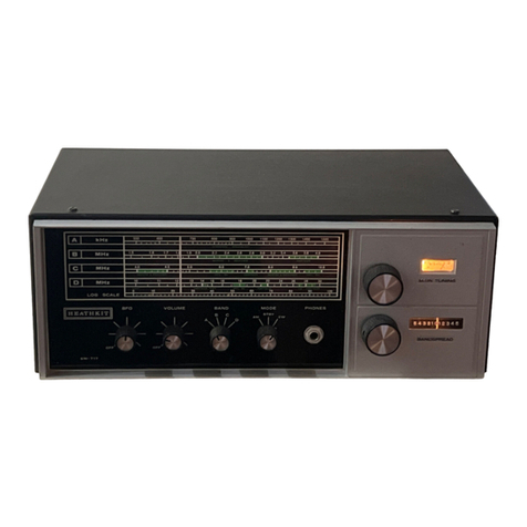
Heathkit
Heathkit SB-300 Installation instructions