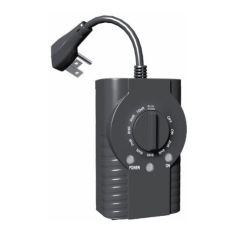
Heatline HLPC-TIMER-120P User manual

HLPC-TIMER-120P /
HLPC-TIMER-240P
Programmable Outlet Cycle Percentage Timer for
Heat-Line Freeze Protection Systems
ToProgramCycle Timer:
1. Turn knob until the “Select CycleTime” arrow aligns
withtriangleto choosetotal cycle time
2. Push the Select Cycle Time button toscroll
through thecycle times
3. Push and hold button to save desired time (LEDblinks)
4. Turn knob until desired ONpercentage ofcyle time
aligns withtriangle
General Information
Timers are a beneficial optional accessory when incorporated with any Heat-
Line freeze protection system. Regardless of the overall system length and or
operating voltage, a Heat-Line Timer will reduce energy costs by decreasing
overall energy consumption. A Timer can be added to Heat-Line systems in
order to duty cycle the heating cable at a selected time interval and percentage.
This field adjustable timer offers true flexibility for repetitive cycle times, and
offers 8 selectable cycle durations with 30 separate percentage positions for
ON time periods. To obtain the best results from your investment, please read
these instructions and acquaint yourself with your purchase before installing
your new timer. Then follow the installation procedures, one step at a time.
This will save you time and minimize the risk of damaging the timer and the
system it controls.
IMPORTANT! Please read all instructions carefully before beginning
installation. Save them for future reference.
WARNING: Only use with 120V-15A or 240V-15A GFCI model Heat-Line
brand self-regulating heating cable systems.
Compatibility
The Heat-Line HLPC-TIMER-120P/240P Programmable Outlet Cycle
Percentage Timer is for use with 120Volt/ 240V, 15 Amp plug-in, 60 Hz
GFCI model Heat-Line Self-Regulating Freeze Protection Systems including
ArcticVent, CARAPACE, EXT5R, EXT3T, Paladin, Heat-Line, Retro-DWS,
Retro-FM, Retro-Line, Rizer-Line, and Tandem-Link systems. This is a timer
control designed to increase energy efficiency of Heat-Line brand products, it is
NOT to be used as a high limit device for other heating cable brands.
Read these rules and instructions carefully. Failure to
follow them could result in serous bodily injury and/or
property damage.
• Check your local building and electrical codes before
installing. You must comply with their rules.
• To reduce the risk of electric shock, this product has a
grounding type plug that has a third (grounding) pin.
This pin will only fit into a grounding type power outlet.
If the plug does not fit into the outlet, contact a qualified
electrician to install the proper outlet.
• Do not use Outdoors. Dry and indoor locations only.
• Disconnect power at the circuit breaker(s) or disconnect
switch(es) before beginning installation and before servicing.
• Do not use the manual off position of the timer for
equipment service. Always disconnect the power at the
circuit breaker(s) or disconnect switch(es).
• Avoid the use of extension cords as this may increase
the risk of electric shock, fire and property damage.
• Check unoccupied residences regularly to ensure that all
systems are operating properly.
• Avoid the use of extension cords as this may increase
the risk of electric shock, fire and property damage.
• Use this thermostat only as described in this manual.
Any other use not recommended by the manufacturer
may increase the risk of fire, electric shock, or injury
to persons.
Installation and Operating Instructions
1of 2
Features
• Plugs directly into standard 120V and 240V 15 Amp receptacles
• Provides 8 field selectable cycle durations:
30 seconds, 1 minute, 3 minutes, 5 minutes, 10 minutes, 30 minutes,
1hour, and 4 hours
• Provides 30 separate detent positions for precise selection of percentage
On time
• User settings stored in non-volatile memory
• Control buttons on front of timer
• No DIP switches to program cycle time
• Easy to install and program
• Manual ON/OFF control allows for temporary or permanent override
• Designed to function in dusty, ammonia, and wash-down environments
• Able to withstand surge of up to 6,000 VAC
• Operating Temperature from 14°F to 129°F (–10°C to 54°C)
• Product weight 1.4 lbs. (0.6 kg)
• Limited 1 year Product Warranty
Ratings
• 120V/60 Hz (120P) and 240V/60 Hz (240P)
• Maximum load is 20 Amps at 120/ 240 Volts
• Power Consumption 2.5 W (maximum)
• Plug and Receptacle NEMA
• Tungsten (Incandescent): 5 Amps @ 240 VAC
• Pilot Duty: 470 VA @ 240 VAC
• Ballast (Fluorescent): 10 Amps @ 277 VAC
• Plug and Receptacle NEMA 5-15R/ 5-15R (120P Model) and
NEMA 6-15R/ 6-15P (240P Model)
Approvals
125V-15A
5-15R
receptacle 5-15P
plug 6-15R
receptacle 6-15P
plug
250V-15A
Energy Controls

HLPC-Timer Installation and Operation Installation
2of 2
Heat-Line Freeze Protection Systems
1095 Green Lake Road
Algonquin Highlands, ON Canada
K0M 1J1
Tel: (705) 754-4545
(800) 584-4944
Fax: (705) 754-4567
www.heatline.com
Important: All information, including illustrations, is believed to be reliable. Users, however, should
independently evaluate the suitability of each product for their particular application. Heat-Line a Division of
Christopher MacLean Ltd. makes no warranties as to the accuracy or completeness of the information, and
disclaims any liability regarding its use. Heat-Line's only obligations are those in the Heat-Line Standard Terms
and Conditions of Sale for this product, and in no case will Heat-Line be liable for any incidental, indirect, or
consequential damages arising from the sale, resale, use, or misuse of the product. Specifications are subject to
change without notice. In addition, Heat-Line reserves the right to make changes—without notification to Buyer—
to processing or materials that do not affect compliance with any applicable specification.
Heat-Line, CARAPACE, EXT5R, EXT3T, Paladin, Retro-DWS, Retro-FM, Retro-Line, Rizer-Line, and TandemLink are
registered trademarks of Heat-Line Corporation.
© 2016 Heat-Line a division of Christopher MacLean Ltd.10/16
ToProgramCycle Timer:
1. Turn knobuntil the“SelectCycle Time” arrowaligns
withtriangleto choosetotal cycle time
2. Pushthe SelectCycleTime buttonto scroll
through thecycle times
3. Pushand holdbutton tosave desired time(LED blinks)
4. Turn knobuntil desiredON percentage of cyletime
aligns withtriangle
Cycle Time Setup
To Program Cycle Timer:
1. Turn knob until the “Select Cycle Time” arrow aligns with triangle to
choose total cycle time.
2. Push the Select Cycle Time button to scroll through cycle times.
3. Push and hold button to save desired time (LED Blinks).
4. Turn knob until desired percentage of cycle time aligns with triangle.
Turning knob to any % position will initiate a new ON period for the
selected Cycle Time.
Higher percentage positions provide additional ON time, and less
OFF time, as shown below.
A permanent ON and a permanent OFF position are provided to allow
manual override of the cycle at any time.
WARNING! Risk of Shock. Do not use the manual OFF position
for equipment service. Always disconnect power at the disconnect
switch(es) or breaker panel.
Cycle Time
Duration
Selector
Knob % ON Time OFF Time
30 sec. 10% 3 sec. 27 sec.
30 sec. 50% 15 sec. 15 sec.
30 sec. 80% 24 sec. 6 sec.
10 min. 10% 1 min. 9 min.
10 min. 50% 5 min. 5 min.
10 min. 80% 8 min. 2 min.
1 hour 10% 6 min. 54 min.
1 hour 50% 30 min. 30 min.
1 hour 80% 48 min. 12 min.
4 hours 10% 24 min. 216 min.
4 hours 50% 120 min. 120 min.
4 hours 80% 192 min. 48 min.
• The OFF indicator will be steady RED in the OFF position and during the
OFF portion of the cycles.
• The ON indicator will be steady GREEN in the ON position and during
the ON portion of the cycles.
• The yellow Cycle Time indicator will be ON except when in the perma-
nent ON or OFF positions.
This manual suits for next models
1
Table of contents
Popular Timer manuals by other brands
NSi INDUSTRIES
NSi INDUSTRIES TORK TU40 instruction sheet
SUPRFIT
SUPRFIT 10001013 instruction manual
STRAINSENSE
STRAINSENSE INTUITIVE INT4-I Installation & operating manual
Kemper
Kemper KHS Timer Installation and operating instructions
Theben
Theben SELEKTA 170 top3 manual
ENFORCER
ENFORCER SA-027WQ installation manual

Intermatic
Intermatic ET7115 user guide
Kenwood
Kenwood AT-50 instruction manual
Ramsey Electronics
Ramsey Electronics UT5A Instuction manual
National Instruments
National Instruments 6612 user manual

Hearth & Home
Hearth & Home WSK-SOUL-TMR Installation and operating instructions
Ascon tecnologic
Ascon tecnologic TCS4 operating instructions
