HeatPumps4Pools ThermoTec LCSPI-95BP Specification sheet

Swimming Pool Heat Pump
-Operation and Installation Manual -
Model:LCSPI-95BP,LCSPI-135BP,LCSPI-180BP,
LCSPI-220BP, LCSPI-280BP

TABLE OF CONTENT
INTRODUCTION…………...………………………………………………………………………………………………..... 2
This manual……………………………………………………………………………………………………………………...2
The Heat Pump………………………………………………………………………………………………………............... 2
SAFETY INSTRUCTIONS ……………………………………………………………………………………………………. 3
Warning ……………………………………………………………………………………………………………………….……. 3
Caution………………………………………………………………………………………………………………………………. 4
CONTENTS……………….…………………………………………………………………………………………….………... 4
OVERVIEW OF THE UNIT ……………………………………………………………………………………….…………. 5
EXPLODED VIEW ……… ……………………………………………………………………………………….………………6
INSTALLATION …………………………………………………………………………………………….…..….…….…….. 7
Installation guidelines …………………………………………………………………………………………….…..………. 7
Locating your Unit….……………………………………………………………………………….…………………………... 7
Water connection …………………………………………………………………………………..…………….…………….. 7
Electrical connection ……………………..……………………………………………………………………….….………… 8
Trial running …………………………………………………………………………………………….……..………………….. 8
OPERATING THE UNIT …………………………………………………………………………………………….…………. 9
Features and functions …………………………………………………………………………………………….…………… 9
User interface ……………………………………..………………………………………………………………………………. 9
Buttons …………………………………………………………………………………………….……………………….……. 10
PARAMETER CHECKING AND ADJUSTMENT…………………………………….……………….………………. 11
Parameter query table……………………………………………………………………………….………………………… 11
Parameter settings…………………………………………………………………………………….………………………… 11
SYSTEM PROTECTIONS/ERROR CODES……………………………….……………………………………………… 12
MAINTENANCE …………………………………………………………………….…………………………………………. 13
TROUBLESHOOTING …………………………………………………………….………………………………………….. 14
ENVIRONMENTAL INFORMATION ……………………………………….………………………………………….. 14
DISPOSAL REQUIREMENTS …………………………………………………………….………………………………… 15
WIRING DIAGRAM …………………………………………………………….………………………………………….….. 16
INVERTER SWIMMING POOL HEAT PUMP TECHNICAL SPECIFICATION…………………………… 17
READ THIS MANUAL CAREFULLY BEFORE OPERATING THE UNIT. DO NOT THROW IT AWAY.
RETAIN FOR FUTURE REFERENCE.
BEFORE OPERATING THE UNIT, ENSURE THE INSTALLATION HAS BEEN CARRIED OUT IN
ACCORDANCE WITH THESE INSTRUCTIONS. IF IN DOUBT CONSULT YOUR LOCAL DEALER.
1

INTRODUCTION
This manual
This manual includes the necessary information to safely install and maintain your Heat Pump. Please
read this manual carefully before you operate the unit.
The Heat Pump
The swimming pool heat pump is one of the most economical ways of heating your swimming pool
efficiently. Using the free renewable energy from the air,it is over 4/5 time more efficient than
traditional heating.The swimming pool heat pump extends your swimming season and gives you
comfort at high level.You could enjoy swimming not only in summer,but also in spring,autumn and
even winter time.
ECO Friendly
The Heat Pump uses R410A Refrigerant which is ozone friendly dramatically reducing Carbon
Emissions.
Titanium heat exchanger
The advanced titanium heat exchanger guarantees a longer life span, free of corrosion. It can be
used with all types of water treatment including chlorine, iodine, bromine and salt water.
Multiple functions
- Cooling and heating functions available
- Auto operation, Auto-restart, Auto defrost
- Auto timer on/off:no human attendance is required
- Wide ambient working range: -10°C to 43°C
Reliable operation
The Heat Pump has several built in safety features, which include insufficient water flow protection,
high/low pressure protection, overload protection, compressor protection.
Self-diagnosis
When there is malfunction,the swimming pool heat pump will make self-diagnosis by displaying
error code on the control panel.To identify the problem,please refer to ERROR CODES pages in this
manual.
2

SAFETY INSTRUCTIONS
To prevent injury to the user, other people or damage to property, the following instructions must be
followed.
Install the unit only when it complies with local regulations, by-laws and standards. Check the main
voltage and frequency. This unit must be earthed and have a supply voltage of 220 – 240 V ~ / 50Hz.
The following safety precautions should always be taken into account:
-Be sure to read the following WARNING before installing the unit.
-After reading these instructions retain for future reference.
Installing the Unit.
Incorrect installation could cause injury due to fire, electric shock or water damage. If in doubt consult
your local dealer or a qualified installer.
Securing the Unit.
The unit should be located on a solid, level, horizontal surface and securely fixed. Ensure free air-flow to
all sides of the unit.
Electrical Connections.
Ensure the correct sized Circuit Breakers, isolators and cables are used.All terminals should be tightly
secured and not prone to stress.
This unit must be earthed.
Materials.
To prevent fire, electric shock and other hazards all materials should be suitable for the specific use of
this unit.
Never use an extension cable to connect the unit to the electric power supply.
If there is no suitable earthed supply available, have one installed by a qualified electrician.
Do not move/repair the unit yourself.
Before carrying out any maintenance, service or repair work, the product must be isolated from the
mains electrical supply. To prevent possible injury, only qualified engineers should carry out these
works.
Do not install the unit in a place where there is a chance of flammable gas leaks.
If there is a gas leak and gas accumulates in the area surrounding the unit, it could cause an explosion.
3

Water Connections.
All plumbing connections should be carried out as per the instructions in this manual. Failure to do so
could result in water damage to property.
Cleaning the Unit.
To prevent injury always shut the power ‘OFF’ when cleaning or servicing the unit.
Error Codes.
If an error code occurs or you can smell burning, isolate the unit immediately and call your local installer.
Avoid contact with the fan when running as this will cause serious injury.
CONTENTS
Before starting the installation, please make sure that all items are found inside the box.
The Unit Box
Item Image QTY Item Image QTY
Swimming pool
heat pump 1 Accessories 1(Set)
Operation and
Installation
Manual
1
4

OVERVIEW OF THE UNIT
5

EXPLODED VIEW
6

INSTALLATION
Installation guidelines
The following information is for guidance only.
Locating the Unit
The unit should be located on a solid, flat, horizontal surface. Ensure 3 metres of free air flow to the
discharge panel and 1 metre to the inlet panel. Ensure adequate access to the controller and for
maintenance purposes.
Precautions
--Avoid locating the unit close to bedrooms or other noise sensitive areas.
--Avoid a location which could create vibration i.e. secured to a solid wall.
--Try to avoid placing the unit under a tree or exposed to extreme conditions.
Water connection
The heat pump is connected to a filtration circuit with a by-pass.
It is imperative that the by-pass is placed after the pump and the filter.
The by-pass generally consists of 3 valves.
This makes it possible to regulate the water flow which passes through the heat pump and to isolate the
heat pump completely for any maintenance work, without cutting the flow of filtered water.
If your installation is equipped with a water treatment system (chlorine, bromine, saltetc) the by-pass must
be installed before the water treatment, with a non-return valve between the by-pass and water treatment
system.
7

Electrical connection
The Electrical supply must correspond to that indicated on the appliance.
All supply cables have to be sized according to the appliance power and installation requirements.
Please refer to below table:
The above are an indication only.Please refer to a qualified Electrician if in doubt.
Use the cable glands and grommets provided inside the heat pump to secure and route the supply cables.
Trial Running
After connecting the unit to the pool system, ensure your installation is complete, with a suitable by-pass
and electrical connections by a qualified engineer.
Be sure that:
1) Appliance is horizontal and on a firm base.
2) Water system has no leaks.
3) Electrical Installation is compliant with all local regulations and standards.
4) The installation requirements described previously have been strictly adhered to.
ATTENTION: THE HEAT PUMP ONLY OPERATES WHEN WATER FLOW IS PRESENT.
You can start up the heat pump following the procedure below:
-Open by-pass valves
-Start pool system pump
-Turn on pool heat pump
-Set controller
8
Features and functions
Basic controller functions
The basic controller functions are:
Turning the heat pump ‘ON’/’OFF’.
24 hour time clock.
Timer ‘ON’ and timer ‘OFF’.
Parameter adjustment
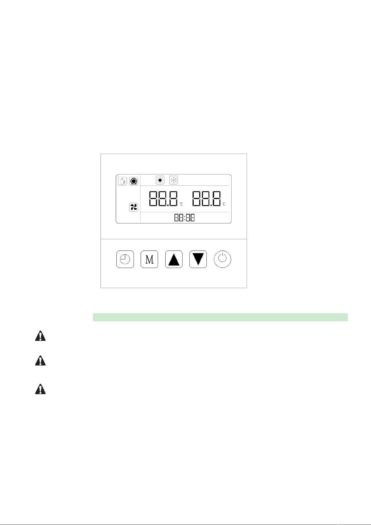
User interface
NEVER LET THE DIGITAL CONTROLLER GET WET. THIS MAY CAUSE AN ELECTRIC SHOCK OR FIRE.
NEVER PRESS THE BUTTONS OF THE DIGITAL CONTROLLER WITH A HARD, POINTED OBJECT.
THIS MAY DAMAGE THE DIGITAL CONTROLLER.
NEVER INSPECT OR SERVICE THE DIGITAL CONTROLLER YOURSELF. REFER TO A QUALIFIED SERVICE
ENGINEER.
9

Buttons
Unit ON/OFF button
Press this button for 3 second to switch unit ON/OFF.
Mode button
Under main operation interface when unit ON,press this button for 3 seconds to switch
heating or cooling modes.
and adjustment buttons
On main operation interface under heating mode,press and buttons to
set target outlet hot water temperature.
On main operation interface under cooling mode,press and buttons to
set target outlet cooling water temperature.
Clock/Timer button
Clock settings:Press for 3 seconds entering into clock flashing status,then press
entering into Clock Setting status:Firstly Hour-digit flashes,press and
to adjust number,press or each time will make number up or
down by one time,if press or for long time,Hour-digit will automatically
up or down.After finishing setting Hour-digit,press entering into Minute-digit
settings,which is same as Hour-digit settings.After Minute-digit settings finished,press
to exit.
Timer settings:Press entering into Timer selection,”Timer 1” will firstly
display,press or to choose different Timers.Then press again to
enter into“Timer1“ settings,press or to adjust target time,other Timers
settings are in same way.
Mandatory defrost
10
Press and for 3 seconds entering into mandatory defrost mode.
Factory reset
Press + + + for 3 seconds entering into factory reset.
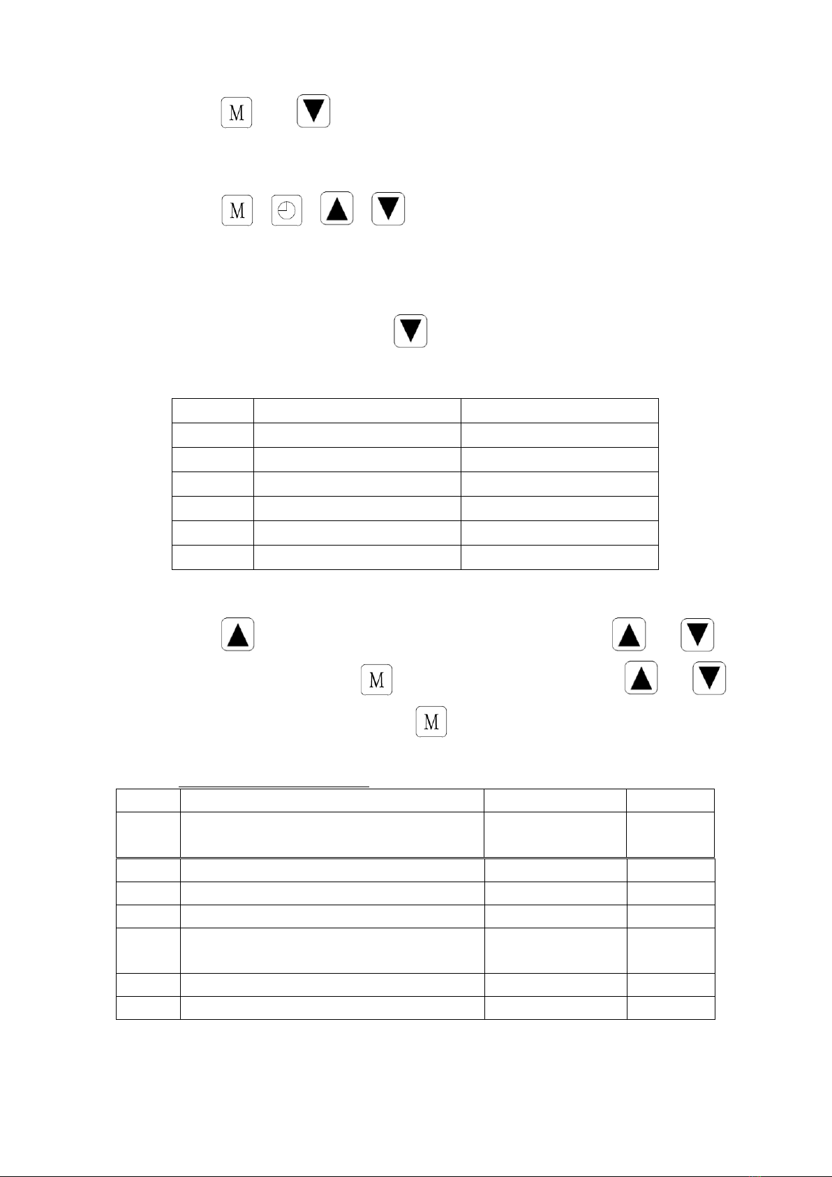
PARAMETER CHECKING AND ADJUSTMENT
Unit running status query
On main operation interface,press for 3 seconds to check temperatures,see the
following table:
Code
Temperature Name
Display Range
01
Inlet water temp
-20~99℃
02
Outlet water temp
-20~99℃
03
Ambient temp
-20~99℃
04
Exhaust gas temp
0~125℃
05
Return gas temp
-20~99℃
06
Coil temp
-20~99℃
System parameter query and settings
Press for 3 seconds entering into parameter query status,press or to
check parameters,then press to modify parameters by using with or ,
after modifications completed,press to confirm and exit.
SYSTEM PARAMETER TABLE
Code
Parameter Name
Adjustment Range
Default
P01 Target/inlet water temp difference
to start compressor
2℃~18℃2℃
P04 Target cooling water temp 7℃~30℃12℃
P05 Target hot water temp 15℃~50℃35℃
P06 Exhaust gas overheat protection gas temp 80℃~125℃120℃
P07 Exhaust gas overheat protection exit
gas temp 50℃~100℃95℃
P08 Compressor current protection 2A~50A 20A
P09 Inlet water temp compensation -5℃~15℃0℃
11

P11
Defrost cycle
20MIN~90MIN
45MIN
P12
Defrost entry coil temp
-15
℃
~-1
℃
-3
℃
P13
Defrost duration time
5MIN~20MIN
10MIN
P14
Defrost exit coil temp
1
℃
~40
℃
20
℃
P15
Ambient/coil temp difference for defrost entry
0
℃
~15
℃
5
℃
P16
Ambient temp for defrost entry
0
℃
~20
℃
17
℃
P17
EEV action cycle
20S~90S
30S
P18
Heating EEV action factor
-5
℃
~10
℃
3
℃
P19
Exhaust gas temp to trigger EEV adjustment
70
℃
~125
℃
95
℃
P20
Defrost EEV open angle
20~450
400
P21
EEV min. open angle
50~150
80
P22
EEV mode option
0:manual/1:auto
1
P23
EEV manual step
20~450
350
P24
Cooling EEV action factor
-5
℃
~10
℃
3
℃
P27 Cooling EEV working mode 0=Ambient temp;
1=Cooling EEV
action factor
0=Ambient
temp
P28 Water pump working option 0=Stop when target
water temp reached
/1=NOT stop when
target water temp
reached
0=Stop
when
target
wate temp
reached
SYSTEM PROTECTIONS/ERROR CODES
When an error occurs or the protection mode is set automatically,the wired controller will display an
error code as below.
Error code
Error Name
Remark
Er 03
Water flow failure
Er 04
Winter anti-freeze protection
Er 05
High pressure failure
Er 06 Low pressure failure
Er 09 Communication failure
Er 10
Inverter module communication
failure(Communication failure
btw. PCB and inverter module)
Er 12
Exhaust gas over-heat protection
Er 15
Inlet water temp sensor failure
Er 16
Coil temp sensor failure
Er 18
Exhaust gas temp sensor failure
Er 20
Inverter module abnormal run protection
12

Er 21
Ambient temp sensor failure
Er 23
Outlet cooling water over-cold protection
Er 27 Outlet water temp sensor failure
Er 29 Return gas temp sensor failure
Er 32 Outlet hot water over-heat
protection
Er 35 Compressor current protection
MAINTENANCE
To protect the paintwork, avoid leaning or putting objects on the shell. External Heat Pump parts can be
wiped with a damp cloth and domestic cleaner. (Warning: Never use cleaning agents containing sand,
soda, acid or chloride as these can damage the surfaces.)
To prevent blockages in the titanium heat exchanger, ensure that the system incorporates a water and
filter treatment facility. In the event of a problem occurring due to contamination, the system should be
cleaned as described below. (Warning: the fins on the finned tube heat exchanger are sharp!).
Cleaning the Heat Exchanger and Pipework
Contamination in the pipes and heat exchanger can reduce the performance of the heat pumps’
titanium heat exchanger. If this is the case, the pipe system and heat exchanger must be cleaned by a
technician.
Use only pressurized drinking water for cleaning.
Cleaning the air system
The finned heat exchanger, fan and condensate outflow should be clear of all obstructions (leaves,
twigs, etc.) before each new heating season. These can be manually removed using compressed air or
by flushing with clean water.
It may be necessary to remove the unit cover and air inlet grid first.
Attention: Before opening the unit, ensure that all electrical supplies are isolated.
To prevent the evaporator and the condensate tray from being damaged, do not use hard or sharp
objects for cleaning.
Under extreme weather conditions (e.g. snow drifts), ice may form on the air intake and exhaust air
outlet grids. If this happens, the ice must be removed in the vicinity of the air intake and exhaust air
outlet grids to ensure that the minimum air flow rate is maintained.
Winter Shutdown.
To prevent frost damage to the unit when not in use the Heat Pump should be drained of all water.
Failing this another form of frost protection should be considered and actioned.
Attention: The warranty does not cover damage caused by inadequate frost protection measures
during the winter.
13

TROUBLESHOOTING
This section provides useful information for diagnosing and correcting certain prolems which may occur.
Before starting the troubleshooting procedure, carry out a thorough visual inspection of the unit and
look for obvious defects such as loose connections or defective wiring.
Before contacting your local dealer, read this chapter carefully.It could save you time and money.
WHEN CARRYING OUT ANY MAINTENANCE ENSURE ADEQUATE PRECAUTIONS ARE TAKEN TO
PREVENT AN ELECTRIC SHOCK .
The hints below are for guidance only. If you cannot solve the problem, consult your installer/local
dealer.
The Heat pump will not run.
Please check:
There is a supply voltage (tripped fuse, power failure).
The switch on the wired controller is switched on, and whether the correct set point temperature
has been set.
The set temperature level cannot be reached.
Please check whether:
The permissible operating conditions for the heat pump have been adhered to (air temperatures
too high or too low).
The air inlet or outlet area is blocked, restricted or very dirty.
There are closed valves or stop-cocks in the water pipes.
The timer works but the programmed actions are executed at the wrong time (e.g. 1 hour too late or
too early).
Please check whether:
The clock and the day of the week are set correctly, adjust if necessary.
If you cannot correct the fault yourself, please contact your after-sales service technician.
Work on the heat pump may only be carried out by authorized and qualified after-sales service
technicians.
ENVIRONMENTAL INFORMATION
This equipment contains fluorinated greenhouse gases covered by the Kyoto Protocol. It should only be
serviced or dismantled by professional trained engineers.
This equipment contains R410A refrigerant in the amount as stated in the specification. Do not vent
R410A into the atmosphere: R410A, is a fluorinated greenhouse gas with a Global Warming Potential
(GWP) = 1975.
14

DISPOSAL REQUIREMENTS
Dismantling of the unit, treatment of the refrigerant, of oil and of other parts must be carried out in
accordance with relevant local and national legislation.
Your product is marked with this symbol. This means that electrical and electronic products
should not be mixed with unsorted household waste.
Do not try to dismantle the system yourself: the dismantling of the system, treatment of the refrigerant,
of oil and other parts must be done by a qualified installer in accordance with relevant local and
national legislation.
Units must be treated at a specialized treatment facility for re-use, recycling and recovery. By ensuring
that this product is disposed of correctly, you will help to prevent potential negative consequences for
the environment and human health. Please contact the installer or local authority for more information.
15

WIRING DIAGRAM
Please refer to the wiring diagram on the electric box.
16
LCSPI-135/180/220BP
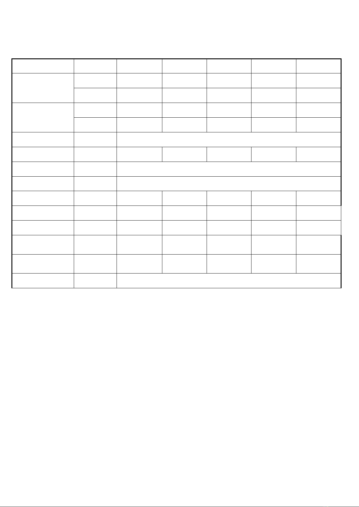
Inverter Swimming Pool Heat Pump Technical Specification
Model LCSPI-95BP LCSPI-135BP LCSPI-180BP LCSPI-220BP LCSPI-280BP
Air 27℃,Water
inlet/outlet:26℃
/28℃, Humidity 80%
Capacity(kW) 10.23~2.55 14.11~3.52 19.12~4.78 22.79~5.69 28.68~7.16
COP 16.11~6.14 16.23~6.19 16.18~6.15 16.09~6.12 16.07~6.11
Air 15℃,Water
inlet/outlet:26℃
/28℃, Humidity 70%
Capacity(kW) 8.06~2.01 11.02~2.75 14.11~3.52 17.18~4.29 21.53~5.38
COP 8.16~4.72 8.22~4.75 8.19~4.73 8.11~4.63 8.05~4.61
Power supply 230V/1Ph/50Hz
Rated power input kW 1.71~0.16 2.32~0.21 3.12~0.29 3.72~0.35 4.71~0.45
Evaporator Hydrophilic fin and copper tube
Heat exchanger Titanium in PVC shell
Water flow volume m³/h 3.5 4.8 5.9 7.5 9.6
Package dimensions mm( L*W*H) 662*724*950 662*724*950 757*826*1080 757*826*1080 757*826*1080
Unit net dimensions mm( L*W*H) 650*688*823 650*688*823 745*792*954 745*792*954 745*792*954
Sound pressure at
1m dB(A) 39~48 40~49 43-52 45~54 45~55
Sound pressure at
10m dB(A) 19~28 20~28 23~32 24~34 25~36
Water proof level IPX4
17
This manual suits for next models
4
Table of contents
Other HeatPumps4Pools Heat Pump manuals


Popular Heat Pump manuals by other brands

STIEBEL ELTRON
STIEBEL ELTRON HSBC 200 S Operation and installation

Glen Dimplex
Glen Dimplex LIK 8TES Installation and operating instruction

Riello
Riello A2WHPR32M/004 manual

evoheat
evoheat EVO 270 manual

Regulus
Regulus CSE2 MIX F W 1F Installation and operation manual

Oilon
Oilon S 180 Installation and operation manual


Dimplex
Dimplex LA 11TAS Installation and operating instructions

Daikin
Daikin FTXR28EV1B9 Service manual

Viessmann
Viessmann VITOCAL 300-G Operating and service instructions

GE
GE AUH2436ZGDA installation instructions

Swim & Fun
Swim & Fun Xpress8 1299 Installation and instruction manual

Daikin
Daikin EGSQH10S18AA9W installation manual