manuals.online logo
Brands
  1. Home
  2. •
  3. Brands
  4. •
  5. Viessmann
  6. •
  7. Heat Pump
  8. •
  9. Viessmann VITOCAL 300-G Training manual

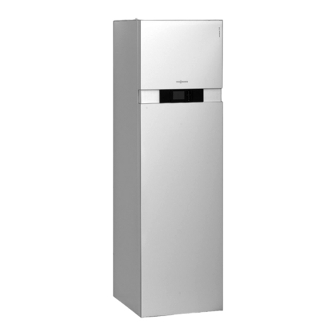
Viessmann VITOCAL 300-G Training manual

Operating and service instructions
for contractors
VIESMANN
Vitocal 300-G
Type BW 301.C17
Ground source heat pump with refrigerant R290 for operation in the ESyCool con-
tainer
For applicability, see the last page
VITOCAL 300-G
5800 917 GB 8/2017 Please keep safe.
2
Please follow these safety instructions closely to
prevent accidents and material losses.
Safety instructions explained
Danger
This symbol warns against the risk of injury.
!Please note
This symbol warns against the risk of material
losses and environmental pollution.
Note
Details identified by the word "Note" contain additional
information.
Target group
These instructions are exclusively intended for quali-
fied contractors.
■Work on the refrigerant circuit involving flammable
refrigerants may only be carried out by authorised
contractors (certification from an industry accredited
body required).
■Work on electrical equipment may only be carried
out by a qualified electrician.
■The system must be commissioned by the system
installer or a qualified person authorised by the
installer.
Regulations to be observed
■National installation regulations
■Statutory regulations for the prevention of accidents
■Statutory regulations for environmental protection
■Codes of practice of the relevant trade associations
■All current safety regulations as defined by DIN, EN,
DVGW, TRF, VDE and all locally applicable stand-
ards
aÖNORM, EN, ÖVGW-TR Gas, ÖVGW-TRF and
ÖVE
cSEV, SUVA, SVGW, SVTI, SWKI, VKF and
EKAS guideline 1942: LPG, part 2
Safety instructions
Safety instructions
5800 917 GB
3
Safety instructions for working on the system
Working on the system
■Isolate the system from the power supply, e.g. by
removing the separate fuse or by means of a mains
isolator, and check that it is no longer live.
Note
In addition to the control circuit there may be several
power circuits.
Danger
Contact with live components can result in
severe injuries. Some components on PCBs
remain live even after the power supply has
been switched off.
Prior to removing covers from the appliances,
wait at least 4 minutes until the voltage has
completely dropped out.
■Safeguard the system against reconnection.
■Wear suitable personal protective equipment when
carrying out any work.
Danger
Hot surfaces can cause burns.
■Before maintenance and service work, switch
OFF the appliance and let it cool down.
■Never touch hot surfaces on the appliance, fit-
tings or pipework.
Danger
Risk of explosion: Electrostatic discharge can
cause sparks which may be ignited by escaping
refrigerant.
Prior to commencing work, touch earthed
objects such as heating or water pipes to dis-
charge static loads.
Danger
Risk of explosion: Electrical components can
cause sparks which may be ignited by escaping
refrigerant.
After every time the control panel is opened or
closed, check the casing door for vapour tight-
ness to EN 60079-15.
Danger
Risk of explosion: Escaping refrigerant can enter
the control panel along short electrical cables
(zone entrainment). In this case, vapour tight-
ness of the control panel is no longer ensured.
Do not trim existing cables.
!Please note
Electronic assemblies can be damaged by elec-
trostatic discharge.
Prior to commencing work, touch earthed
objects such as heating or water pipes to dis-
charge static loads.
Work on the refrigerant circuit
R290 refrigerant (propane) is an air displacing, colour-
less, flammable, odourless gas which forms explosive
mixtures with air.
Perform the following measures before beginning work
on the refrigerant circuit:
■Check refrigerant circuit for leaks.
■Ensure very good ventilation especially in the floor
area and sustain this for the duration of the work.
■Inform the following people about the nature of the
work to be carried out:
–All maintenance personnel
–Everyone who is present in the vicinity of the sys-
tem.
■Inspect the area immediately around the heat pump
for flammable materials and ignition sources:
Remove any flammable materials and ignition sour-
ces found.
■Cordon off the area around the ESyCool container.
■Before, during and after the work, check the sur-
rounding area for escaping refrigerant using an
explosion-proof refrigerant detector suitable for
R290.
This refrigerant detector must not generate any
sparks and must be sealed appropriately.
■In the following cases, a CO2 or powder fire extin-
guisher must be close at hand:
–When the system is being recharged with refriger-
ant.
–When soldering or welding work is being carried
out.
■Display signs prohibiting smoking.
Danger
Handling refrigerant can cause serious damage
to health. There is a risk of asphyxiation if it is
breathed in.
■Avoid direct contact with liquid refrigerant.
Wear personal protective equipment when
handling liquid gas.
■Never breathe in refrigerant vapours.
Danger
Escaping refrigerant can lead to explosions
resulting in extremely serious injury.
■Never drill into or ignite the refrigerant circuit.
■Take measures to prevent electrostatic
charge.
■Do not smoke. Prevent naked flames and
sparks. Never switch lights or electrical appli-
ances on or off.
Safety instructions
Safety instructions (cont.)
5800 917 GB
4
Repair work
!Please note
Repairing components that fulfil a safety func-
tion can compromise the safe operation of the
system.
■Replace faulty components only with genuine
Viessmann spare parts.
■Service work must be carried out in accord-
ance with the information provided by
Viessmann.
Auxiliary components, spare and wearing parts
!Please note
Spare and wearing parts that have not been tes-
ted together with the system can compromise its
function. Installing non-authorised components
and making non-approved modifications or con-
versions can compromise safety and may inva-
lidate our warranty.
For replacements, use only original spare parts
supplied or approved by Viessmann.
Safety instructions for operating the heat pump
■The heat pump may only be operated in the ESyCool
container with explosion protection provided for this
purpose; max. 4 heat pumps in one container.
■No permanent ignition sources may be installed in
this container, e.g. open flames, other gas applian-
ces or electric heaters.
■The heat pump may only be operated at ambient
temperatures of between 0 and 35 °C.
■Always keep the ventilation apertures in the front
panel free so that refrigerant can flow out of the heat
pump unobstructed in the event of a leak.
What to do if refrigerant escapes
Danger
Escaping refrigerant can lead to explosions
resulting in extremely serious injury.
■Ensure very good ventilation especially in the
floor area.
■Do not smoke. Prevent naked flames and
sparks. Never switch lights or electrical appli-
ances on or off.
■Evacuate any people from the danger zone.
■Notify contractors authorised to work on the
refrigerant circuit from outside the ESyCool
container.
■Shut off the power supply to the ESyCool con-
tainer from a safe place (outside the con-
tainer).
Safety instructions
Safety instructions (cont.)
5800 917 GB
5
1. Information Disposal of packaging ............................................................................ 8
Symbols ................................................................................................. 8
Intended use .......................................................................................... 9
Permissible ambient temperatures in the installation room ................... 9
2. Introduction Scope of functions ................................................................................. 10
Diagnostic functions and setting levels .................................................. 10
■System user ........................................................................................ 10
■Contractor ........................................................................................... 10
3. Operation Opening the heat pump control unit ....................................................... 11
Programming unit .................................................................................. 12
■"Operating info" ................................................................................ 12
■Symbols on the display ....................................................................... 12
Standard display .................................................................................... 12
■Screensaver ....................................................................................... 13
Extended menu ...................................................................................... 13
■Menu overview ................................................................................... 14
Service menu ......................................................................................... 14
■Menu overview ................................................................................... 15
4. Switching on and off Starting the heat pump .......................................................................... 16
Shutting down the heat pump ................................................................ 16
5. Settings Setting the time and date ....................................................................... 17
Language selection ................................................................................ 17
Setting the display contrast .................................................................... 17
Setting the display brightness ................................................................ 17
Setting the temperature unit (°C/°F) ...................................................... 17
6. Manual mode ................................................................................................................ 18
7. Function description External control ...................................................................................... 19
8. Troubleshooting Calling up messages ............................................................................. 20
Message overview ................................................................................. 21
■01 System fault ................................................................................... 21
■02 Data error stand.settg .................................................................... 21
■05 Refrigerant circuit .......................................................................... 21
■07 Fault refrigerant circ ....................................................................... 21
■10 Outside temp. sensor .................................................................... 21
■18 Outside temp. sensor .................................................................... 21
■20 Flow sensor secondary .................................................................. 22
■21 Return sensor secndry .................................................................. 22
■28 Flow sensor secondary .................................................................. 22
■29 Return sensor secndry .................................................................. 22
■30 Flow sensor primary ...................................................................... 23
■31 Return sensor primary ................................................................... 23
■38 Flow sensor primary ...................................................................... 23
■39 Return sensor primary ................................................................... 23
■A9 Heat pump ..................................................................................... 24
■B0 Device recognition ......................................................................... 24
■B4 AD converter ................................................................................. 24
■B5 Hardware ....................................................................................... 24
■BF Communication module ................................................................ 25
■C2 Power supply ................................................................................ 25
■C5 Power-OFF ................................................................................... 25
■C9 Refrigerant circ (SHD) ................................................................... 25
■CA Protectn device primry .................................................................. 26
■CB Flow temp. primary ....................................................................... 26
Index
Index
5800 917 GB
6
■CC Coding card .................................................................................. 26
■CF Communication module ................................................................ 26
■D1 Compressor safety ........................................................................ 27
■D3 Low pressure ................................................................................ 27
■D4 Control high pressure .................................................................... 27
■EE KM BUS subscriber ...................................................................... 28
■EF Modbus subscriber ........................................................................ 28
■F2 Parameter 5030 ............................................................................. 28
■FF New start ....................................................................................... 28
No display on programming unit screen ................................................ 28
9. Diagnosis Diagnosis (service scans) ...................................................................... 29
System overview .................................................................................... 30
System ................................................................................................... 31
■Timer ................................................................................................... 31
■Integral ................................................................................................ 32
■Logbook .............................................................................................. 33
Heat pump ............................................................................................. 35
■Compressor runtime ........................................................................... 35
Refrigerant circuit ................................................................................... 36
■Refrigerant circ controller ................................................................... 36
■Compressor travel .............................................................................. 37
■Compressor path ................................................................................ 37
■Message history ................................................................................. 38
Brief scan ............................................................................................... 40
System information ................................................................................ 41
10. Actuator test Actuator test (testing outputs) ................................................................ 43
11. Sensor matching ................................................................................................................ 44
12. Service functions LON subscriber check ........................................................................... 45
Subscribers (Modbus/KM-BUS) ............................................................. 45
Service PIN ............................................................................................ 46
Function check ....................................................................................... 46
Saving/loading settings .......................................................................... 46
■Saving settings ................................................................................... 47
■Load settings ...................................................................................... 47
13. Control unit settings Coding level 1 in the service menu ........................................................ 48
■Calling up Coding level 1 .................................................................... 48
■Deactivating the service menu ........................................................... 48
Setting parameters ................................................................................ 49
■Bit field ................................................................................................ 49
Restoring delivered condition (reset) ..................................................... 50
14. Parameter group System
definition
Calling up the parameter group ............................................................. 51
7000 System scheme ............................................................................ 51
7002 to 7013 .......................................................................................... 51
7014 Effect of external demand on heat pump/heating circuits ............. 51
7015 to 7017 .......................................................................................... 51
7018 Temperature range input 0..10V ................................................... 51
7019 Priority external demand ............................................................... 51
701A to 701C ......................................................................................... 52
15. Parameter group Com-
pressor
Calling up the parameter group ............................................................. 53
5000 Enable compressor ....................................................................... 53
5012 Enable use of compressor stage .................................................. 53
5030 Output compressor stage ............................................................. 53
5043 Primary source output ................................................................... 53
Index
Index
5800 917 GB
7
16. Parameter group Internal
hydraulics
Calling up the parameter group ............................................................. 54
7300 to 7303 .......................................................................................... 54
730C Set flow temperature external demand ........................................ 54
730D to 7379 ......................................................................................... 54
17. Parameter group Primary
source
Calling up the parameter group ............................................................. 55
7400 to 7401 .......................................................................................... 55
18. Parameter group Smart
Grid
Calling up the parameter group ............................................................. 56
7E80 to 7E95 ......................................................................................... 56
19. Parameter group Time Calling up the parameter group ............................................................. 57
7C00 to 7C06 Automatic changeover summertime - wintertime ........... 57
20. Parameter group Commu-
nication
Calling up the parameter group ............................................................. 58
7707 to 77FF ......................................................................................... 58
21. Parameter group Control Calling up the parameter group ............................................................. 59
8800 Lock out controls ........................................................................... 59
8801 to 8811 .......................................................................................... 59
22. Maintenance Checklist for maintenance work ............................................................. 60
Removing the outer panels .................................................................... 64
Electrical connections to the heat pump ................................................ 64
■EEV PCB ............................................................................................ 66
Checking the control panel for vapour tightness ................................... 66
Opening the heat pump control unit ....................................................... 67
Electrical connections on the heat pump control unit ............................ 68
■Information regarding the electrical connections ................................ 69
■Main and expansion PCB ................................................................... 69
■Cross connect PCB ............................................................................ 71
■Controller and sensor PCB ................................................................. 73
Checking the fuses ................................................................................ 74
Opening the casing door ........................................................................ 74
Overview of internal components .......................................................... 75
Extracting the refrigerant ....................................................................... 76
Topping up the refrigerant ...................................................................... 78
Draining the heat pump on the primary/secondary side ........................ 78
The appliance is too noisy ..................................................................... 78
Condensation and humidity in the heat pump module .......................... 78
Check the diaphragm grommets ............................................................ 79
Checking sensors .................................................................................. 79
■Viessmann Pt500A temperature sensor (green marking) ................... 80
■Pressure sensors curve ...................................................................... 81
23. Parts lists Overview of assemblies ......................................................................... 83
Casing .................................................................................................... 84
Electrical equipment .............................................................................. 86
Heat pump module ................................................................................ 88
Hydraulics .............................................................................................. 90
Miscellaneous ........................................................................................ 92
24. Specification ................................................................................................................ 94
25. Appendix Final decommissioning and disposal ..................................................... 96
■Extracting the refrigerant .................................................................... 96
■Disposing of the compressor and compressor oil ............................... 96
26. Certificates Extended declaration of incorporation for an incomplete appliance ...... 98
27. Keyword index ................................................................................................................100
Index
Index (cont.)
5800 917 GB
8
Please dispose of packaging waste in line with statu-
tory regulations.
DE: Use the disposal system organised by
Viessmann.
AT: Use the ARA statutory disposal system (Altstoff
Recycling Austria AG, licence number 5766).
CH: Packaging waste is disposed of by the HVAC
contractor.
Symbols
Symbols in these instructions
Symbol Meaning
Reference to other document containing
further information
1.
Step in a diagram:
The numbers correspond to the order in
which the steps are carried out.
Warning of material losses and environ-
mental pollution
Live electrical area
Pay particular attention.
■Component must audibly click into place.
or
■Acoustic signal
■Fit new component.
or
■In conjunction with a tool: Clean the sur-
face.
Dispose of component correctly.
Dispose of component at a suitable collec-
tion point. Do not dispose of component in
domestic waste.
Symbols on the heat pump
Symbol Meaning
Follow the operating manual
(ISO 7000 - 0790)
Follow the instructions for use/operating in-
structions (ISO 7000 - 1641)
Service display:
Refer to the operating manual
(ISO 7000 - 1659)
Information
Disposal of packaging
5800 917 GB
Information
9
The appliance is only intended to be installed and
operated in the ESyCool container, with due attention
paid to the associated installation and dismantling
instructions as well as the operating and service
instructions. The container must be equipped with gas
sensors and a safety concept suitable for R290 refrig-
erant (propane). The safety concept must include a
safety heat exchanger outside the building which pre-
vents refrigerant entering the building in the case of a
refrigerant or water leak. Equivalent measures are per-
missible.
The appliance can only be used for the following pur-
poses:
■Central heating
■Cooling in conjunction with refrigerators and cold-
rooms
Intended use presupposes that a fixed installation in
conjunction with permissible, system-specific compo-
nents has been carried out.
Commercial or industrial use for a purpose other than
central heating and cooling in conjunction with refriger-
ators and coldrooms shall be deemed inappropriate.
Incorrect usage or operation of the appliance (e.g. the
appliance being opened by the system user) is prohibi-
ted and will result in an exclusion of liability. Incorrect
usage also occurs if the components in the heat pump
and system are modified from their intended function.
Permissible ambient temperatures in the installation room
!Please note
Outside the indicated temperature ranges faults
may occur in the heat pump.
Ensure the temperature in the installation room
is between 0 and 35 °C.
Information
Intended use
5800 917 GB
Information
10
These operating and service instructions include the
following information on the Vitocal 300-G, type
BW 301.C17 heat pump with R290 refrigerant (pro-
pane) and heat pump control unit Vitotronic 200, type
WO1C:
■Control unit parameters
■Diagnostic options for the refrigerant circuit
■Troubleshooting measures
■Overview of electrical connections
Diagnostic functions and setting levels
To avoid incorrect operation of the heat pump and
other system components, not all menus are available
at every setting level. For example, control parameters
can only be called up at the contractor setting level.
System user
The "System user" setting level is suitable for people
who have been instructed in the operation of the heat
pump.
The appliance is operated in the extended menu: See
page 13.
Contractor
In this setting level, the functions in the service menu
are available, e.g. the parameters of "Coding level 1".
Service menu: See page 14.
■The "Contractor" setting level includes the functions
of the "System user" setting level.
■The settings in "Coding level 1" may only be made
by persons who have taken part in special training
for the heat pump.
Introduction
Scope of functions
5800 917 GB
Information
11
Fig. 1
The heat pump control unit is mounted as a separate
enclosure on a wall in the container.
Front of the heat pump control unit
B
D
A
External control
Flow temperature 40°C
C
Fig. 2
AFault indicator (red)
BON indicator (green)
CProgramming unit
DON/OFF switch
Operation
Opening the heat pump control unit
5800 917 GB
Operation
12
External control
Flow temperature 40°C
Fig. 3
Return to previous step in the menu or cancel a
setting that has been started.
Cursor keys for scrolling through the menu or for
setting values
OK Confirm selection or save the setting made.
Call up "Operating info" or additional information
on the selected menu.
Call up extended menu.
"Operating info"
The "Operating info" provides information in the form
of a quick guide that contains basic explanations on
appliance operation.
Calling up "Operating info":
■If the screensaver is active: Press
.
■From any point in the menu: Press
until the standard display is shown. Press
.
Symbols on the display
These symbols are not always displayed, but appear
subject to the operating state of the heat pump.
Displays:
Frost protection is active.
Compressor is running.
Output for primary pump is being switched.
Messages: See page 20.
Note
Warning
Fault
Standard display
The heat pump is in the "External control" operating
state.
For further operation either switch to the extended
menu (see the following chapter) or to the service
menu (see page 14).
Operation
Programming unit
5800 917 GB
Operation
13
External control
Flow temperature 40°C
1
Fig. 4
Note
A number between 1 and 4 may additionally be shown
on the display. This number is an appliance number
set in the control unit. The number has no effect on the
heat pump’s operation.
Screensaver
The screensaver becomes active if no settings have
been made on the programming unit for a few minutes.
The display brightness is reduced.
Terminating the screensaver
Press OK.
The standard display appears.
Extended menu
The extended menu serves to adjust settings and call
up information on the operating state of the heat pump.
Calling up the extended menu
■If the screensaver is active:
Press OK and then .
■From any point in the menu: Press
.
Note
Operation within the extended menu can be blocked
with "Lock out controls 8800". The following func-
tions are still available when the extended menu is
blocked:
■Calling up messages: See page 20.
■Manual mode: See page 18.
Menu
Service
Continue with
Manual mode
Settings
Information
OK
Fig. 5
Operation
Standard display (cont.)
5800 917 GB
Operation
14
Menu overview
"Information"
"System"
"Operating status system"
"Central fault"
"Time"
"Date"
"Heat pump"
"Compressor"
"Primary pump"
"Secondary pump"
"Hours run compressor"
"No. of starts comprssr"
"Daily log"
"Settings": See page 17.
"Time / Date"
"Language"
"Contrast"
"Brightness"
"Control"
"Screen saver"
"Temperature unit"
"Manual mode": See page 18.
Service menu
In the service menu, important diagnostic and service
functions are available. In addition, the control unit
parameters can also be set.
Calling up the service menu
Press OK + å simultaneously and hold for approx.
4 s.
Terminating the service menu
■Confirm "Terminate service?" with "Yes".
or
■Automatic if there has been no operator action for
30 min
Operation
Extended menu (cont.)
5800 917 GB
Operation
15
Menu overview
"Service"
"Diagnosis" See page 29.
"Actuator test" See page 43.
"Coding level 1" See page 48.
"Sensor matching" See page 44.
"Message history" See page 20.
"Service functions" See page 45.
Operation
Service menu (cont.)
5800 917 GB
Operation
16
1. Switch ON the power supply, e.g. at a separate
fuse or mains isolator.
2. Switch on the ON/OFF switch on the heat pump
control unit: See fig. 2 on page 11.
After a short time, the standard display is shown:
See fig. 4 on page 13.
The green ON indicator illuminates. The heat pump
is now ready for operation.
Shutting down the heat pump
1. Switch off the ON/OFF switch on the heat pump
control unit: See fig. 2 on page 11.
2. Isolate the system from the power supply, e.g. at a
separate fuse or a mains isolator.
!Please note
If outside temperatures below 3 °C are
expected there is a risk of frost damage to
the heat pump and the pipework.
Take appropriate measures to protect the
heat pump and pipework against frost.
Switching on and off
Starting the heat pump
5800 917 GB
Operation
17
1. Extended menu:
2. "Settings"
3. "Time / Date"
4. Set the time and date.
Language selection
1. Extended menu:
2. "Settings"
3. "Language"
4. Select the required language.
Setting the display contrast
1. Extended menu:
2. "Settings"
3. "Contrast"
4. Set the required contrast.
Setting the display brightness
The display brightness for "Control" and "Screen
saver" can be adjusted to make the menu texts easier
to read.
1. Extended menu:
2. "Settings"
3. "Brightness"
4. "Control" or "Screen saver"
5. Set the required brightness.
Setting the temperature unit (°C/°F)
Factory setting: °C
1. Extended menu:
2. "Settings"
3. "Temperature unit"
4. Set temperature unit "°C" or "°F".
Settings
Setting the time and date
5800 917 GB
Operation
18
In manual mode, unregulated heating with a set flow
temperature of 45 °C takes place.
1. Extended menu:
2. "Manual mode"
Manual mode
Terminate with OK
Fig. 6
Note
Scan values and information on settings can be called
up in the extended menu while manual mode is active.
For this, press . Any changed settings become
active after manual mode ends.
Manual mode
Manual mode
5800 917 GB
Operation
19
When a heat demand occurs, the heat pump is started
by a higher control unit, via the X3.12/X3.13 contact on
the cross connect PCB (floating contact required): See
page 71.
The heat pump control unit transmits the parameters
and measured values for heat pump operation to the
higher control unit via Modbus.
When "External control" is active, the compressor
always runs at maximum output. The set flow tempera-
ture is permanently set to 50 °C.
Note
Although neither the primary nor secondary pump are
directly connected to the heat pump control unit, the
designated outputs for some functions will nonetheless
be triggered. The corresponding pump symbols will
thus sometimes be displayed.
Function description
External control
5800 917 GB
Functions
20
With all messages, the associated message symbol
flashes on the display.
The message text and message code are displayed by
pressing OK: See "Message overview".
Fault
Acknowledge with OK
Heat pump A9
Return sensor secndry 21
Fig. 7
Explanation of messages
Information " "
The appliance is ready for use. Observe the informa-
tion.
Warning " "
The appliance operates with limited functions. Remove
the cause for the warning.
Fault " "
■The red fault indicator on the heat pump control unit
flashes.
■The system is no longer in standard mode. The fault
should be remedied without delay.
■The central fault message terminal is activated.
Acknowledging messages
1. Call up the message: See page 20.
2. Press OK.
3. Confirm query with "Yes".
Note
■Any signalling equipment (e.g. an alarm) that is con-
nected will be deactivated when the fault message is
acknowledged.
■If the cause of the fault can only be removed at a
later time, the fault message will be redisplayed the
following day. The signalling equipment is switched
on again (if installed).
The message is adopted into the "Fault", "Warning"
or "Note" menu within the extended menu.
Calling acknowledged messages up again
1. Extended menu:
2. "Fault", "Warning" or "Note"
Reading out messages from the message history
■Messages cannot be acknowledged in the message
history.
■Messages are listed in chronological order. The most
recent message is listed first.
■Up to 30 entries are stored.
1. Service menu:
Press OK + å simultaneously and hold for
approx. 4 s.
2. "Message history"
3. Scan further information on the required message
with OK.
Continue with
Warnings noted 02
08.03.2012 10:28 o'clock
The system configuration
is incorrect.
Incorrect system scheme,
Configuration fault 03
AB
Fig. 8
AMessage code
BAdditional code
■Not available for every message
■Different interpretations are possible, subject to
the message concerned
Note
The service menu remains active until it is disabled
with "Terminate service?", or if no key is pressed for
30 min.
Troubleshooting
Calling up messages
5800 917 GB
Maintenance

Other manuals for VITOCAL 300-G

12

This manual suits for next models

1

Other Viessmann Heat Pump manuals

Viessmann VITOCAL 300-G Operating instructions

Viessmann

Viessmann VITOCAL 300-G Operating instructions

Viessmann VITOCAL 300-A User manual

Viessmann

Viessmann VITOCAL 300-A User manual

Viessmann VITOCAL 300-A Quick guide

Viessmann

Viessmann VITOCAL 300-A Quick guide

Viessmann VITOCAL 300-A Quick guide

Viessmann

Viessmann VITOCAL 300-A Quick guide

Viessmann VITOCAL 300-G Quick guide

Viessmann

Viessmann VITOCAL 300-G Quick guide

Viessmann KWT Vitocal 350-G Pro Series Quick guide

Viessmann

Viessmann KWT Vitocal 350-G Pro Series Quick guide

Viessmann KWT Vitocal 350-G Pro Series Operating instructions

Viessmann

Viessmann KWT Vitocal 350-G Pro Series Operating instructions

Viessmann Vitocal 242-S Quick guide

Viessmann

Viessmann Vitocal 242-S Quick guide

Viessmann VITOCAL 222-G Operating instructions

Viessmann

Viessmann VITOCAL 222-G Operating instructions

Viessmann Vitocal 350-A AWHO 351.A Series Quick guide

Viessmann

Viessmann Vitocal 350-A AWHO 351.A Series Quick guide

Viessmann VITOCAL 242-G Quick guide

Viessmann

Viessmann VITOCAL 242-G Quick guide

Viessmann VITOCAL 350-A Quick guide

Viessmann

Viessmann VITOCAL 350-A Quick guide

Viessmann VITOCAL 300-G Quick guide

Viessmann

Viessmann VITOCAL 300-G Quick guide

Viessmann VITOCAL 300-G User manual

Viessmann

Viessmann VITOCAL 300-G User manual

Viessmann VITOCAL 151-A Quick guide

Viessmann

Viessmann VITOCAL 151-A Quick guide

Viessmann Vitocal 200-S Operating instructions

Viessmann

Viessmann Vitocal 200-S Operating instructions

Viessmann Vitocal 350-G Quick guide

Viessmann

Viessmann Vitocal 350-G Quick guide

Viessmann VITOCAL 300-G PRO Type BW 2150 Quick guide

Viessmann

Viessmann VITOCAL 300-G PRO Type BW 2150 Quick guide

Viessmann VITOCAL 300-G PRO Type BW 2150 Operating instructions

Viessmann

Viessmann VITOCAL 300-G PRO Type BW 2150 Operating instructions

Viessmann Vitocal 222-S Quick guide

Viessmann

Viessmann Vitocal 222-S Quick guide

Viessmann Vitocal 242-S Quick guide

Viessmann

Viessmann Vitocal 242-S Quick guide

Viessmann VITOCAL 222-G Quick start guide

Viessmann

Viessmann VITOCAL 222-G Quick start guide

Viessmann VITOCAL Series Quick start guide

Viessmann

Viessmann VITOCAL Series Quick start guide

Viessmann VITOCAL 060-A Operating instructions

Viessmann

Viessmann VITOCAL 060-A Operating instructions

Popular Heat Pump manuals by other brands

Riello AARIA START Installation and technical service instructions

Riello

Riello AARIA START Installation and technical service instructions

STIEBEL ELTRON WPE-I 04 H 230 Premium Operation and installation

STIEBEL ELTRON

STIEBEL ELTRON WPE-I 04 H 230 Premium Operation and installation

Oasis I Series Installation & operation manual

Oasis

Oasis I Series Installation & operation manual

Friedrich VERT-I-PAK VEA09 Product profile

Friedrich

Friedrich VERT-I-PAK VEA09 Product profile

Carrier 38BYG Series Product data

Carrier

Carrier 38BYG Series Product data

Dimplex LA 16 MI operating instructions

Dimplex

Dimplex LA 16 MI operating instructions

Kaisai MONO KHC-22RX3 installation manual

Kaisai

Kaisai MONO KHC-22RX3 installation manual

Fondital PROCIDA AWM X6 installation manual

Fondital

Fondital PROCIDA AWM X6 installation manual

Daikin FVY71LAVE Service manual

Daikin

Daikin FVY71LAVE Service manual

LG Multi V III Solo ARUN LM3 Series Service manual

LG

LG Multi V III Solo ARUN LM3 Series Service manual

Rotex RRRQ011AAV1 installation manual

Rotex

Rotex RRRQ011AAV1 installation manual

DURASTAR DRPTAC07Y41G1A Owners and installation manual

DURASTAR

DURASTAR DRPTAC07Y41G1A Owners and installation manual

Daikin Inverter CTXS09GVJU Service manual

Daikin

Daikin Inverter CTXS09GVJU Service manual

Hayward Pool Products HP50CL Installation instructions manual

Hayward Pool Products

Hayward Pool Products HP50CL Installation instructions manual

CLIVET WSAN-XPR Series Installation and use manual

CLIVET

CLIVET WSAN-XPR Series Installation and use manual

Danfoss ECL Comfort 100M user guide

Danfoss

Danfoss ECL Comfort 100M user guide

Payne PH10 installation manual

Payne

Payne PH10 installation manual

Nibe F2040-6 Installer manual

Nibe

Nibe F2040-6 Installer manual

manuals.online logo
manuals.online logoBrands
  • About & Mission
  • Contact us
  • Privacy Policy
  • Terms and Conditions

Copyright 2025 Manuals.Online. All Rights Reserved.