Heatstore HS55/3/10N Guide

1
Installation and User Instructions
HS55/3/10N, HS55/3/7N, HS55/1/7N
Please read and understand these instructions before starting work.
Please leave this leaet with the user following installation
PACK CONTENTS
Heater, Spout, Valve, Fixing screws and plugs, Installation and
User Instructions.
WARNING
This water heater must only be installed by qualied persons.
36005793_issue_07
HEATSTORE
OPEN OUTLET WATER HEATERS

2
This water heater must be installed and commissioned by a competent person. Please read
and understand these instructions prior to installing your water heater. Particular attention
should be paid to section three headed INSTALLATION. Following installation the operation
of the heater should be explained to the user and these instructions left with them for
future reference.
This appliance can be used by children aged from 8 years
and above and persons with reduced physical sensory or
mental capabilities or lack of experience and knowledge if
they have been given supervision or instruction concerning
use of the appliance in a safe way and understand
the hazards involved. Children shall not play with the
appliance. Cleaning and user maintenance shall not be
made by children without supervision.
Children must be supervised to ensure they do not play
with the appliance.
Electrical rating ...............................................1.17/1.2kW@230/240V~
.......................................................................2.75/3.0kW@230/240V~
Capacities .......................................................7 & 10 litres
Weight (full)....................................................7 litre - 9.3kg, 10 litre - 12.5kg
Rated Pressure.................................................0Mpa (0bar)
Minimum recommended supply pressure Mains fed or cistern fed (3m head required)
Temperature range..........................................10 to 70°C

3
INSTALLATION
1. The cold water inlet must always be on the right.
2. In both under and oversink installations the inlet and outlet connections must remain
beneath the heater. (See Figure 3 for undersink installation).
3. The outlet of this water heater acts as a vent and must not be blocked or restricted in
any way.
4. Only Heatstore open outlet taps and spouts should be used with this water heater. A
full range is available, please consult either your distributor or Heatstore for further
information.
5. The installation must be carried out in accordance with the relevant requirements
of:
• The appropriate Building Regulations either The Building Regulations, The Build
ing Regulations (Scotland) or Building Regulations (Northern Ireland).
• The Water Fittings Regulations or Water Byelaws in Scotland.
POSITIONING THE WATER HEATER
1. Select a suitable site but check that:
a) There is enough clearance under the heater to allow removal of the element plate
(210mm).
b) When using the outlet spout, it will swing over the sink (or sinks) to be supplied.
c) There are no hidden services where the wall is to be drilled.
2. Mark the position of the xing holes (as shown in Figure 4).
3. Drill and plug the hole positions.
4. Screw in the top two screws leaving head 3mm from the wall.
5. Hang the heater on the two top screws.
6. Screw in bottom screw to secure heater.
PLUMBING REQUIREMENTS
The water heater is designed to be connected directly to the mains via the valve
provided or Heatstore open outlet tap ttings.
It is recommended that a WRAS listed isolating valve (not supplied) be tted in the
water supply pipe to the heater to allow for servicing.
SPOUT AND VALVE
1. Connect the control valve supplied to the inlet pipe on the water heater.
2. Connect the cold water main to the control valve using 15mm outside diameter pipe
(either copper to BS 2871 or stainless steel to BS 4127).
3. Push the outlet spout directly into the outlet tting.
TO REMOVE OUTLET SPOUT
1. Remove terminal cover.
1. Push grey ring upwards towards body of tting.
2. Pull spout downwards.

4
OPEN OUTLET TAP FITTING
1. Ensure electricity supply is switched off.
2. Remove terminal cover (using a at bladed screwdriver to relieve snaps located
towards the front of the terminal cover either side).
3.Plumb from the open outlet tap tting using 15mm outside diameter copper pipe to
the 15x15mm john guest tting in the water heater. The tap set will have its own instal-
lation instructions.
ELECTRICAL REQUIREMENTS (REFER TO FIGURE 2 - WIRING
DIAGRAM).
•WARNING: THIS APPLIANCE MUST BE EARTHED.
•CONNECT ONLY TO 230 / 240V AC SUPPLY.
•NOMINAL CROSS SECTION OF SUPPLY CABLE MUST BE AT LEAST
15mm2.
•A DOUBLE POLE ISOLATING SWITCH WITH A CONTACT SEPARATION OF
AT LEAST 3mm IN EACH POLE MUST BE INCORPORATED IN THE
SUPPLY.
•ELECTRICAL INSTALLATION MUST CONFORM TO THE CURRENT I.E.E.
WIRING REGULATIONS.
1. Remove terminal cover (as described above).
2. Strip the outer sheath and insulation on the cable to the required lengths, making
sure the outer sheath of the cable will be held in the cable grip when the connections
are made.
3. Loosen the top screws securing the bar at the cable grip.
4. Pass the cable through the cable grip.
5. Make the connections to the terminal block as follows:
-Live (brown or red wire) to terminal marked “L”
-Neutral (blue or black wire) to terminal marked “N”
-Earth (green or green/yellow wire) to terminal marked
6. Secure the cable in the cable grip by tightening the two screws.
7. Set the adjustable thermostat by rotating the control to the required temperature, the
reading being taken from the top of the dial. It is recommended that it is set to
lowest acceptable temperature to meet user requirements. This will minimise the
risk of scalding and reduce the level of scaling in hard water areas.
8. Replace terminal cover.
OPERATION
DO NOT SWITCH ON HEATER UNTIL IT IS FILLED WITH WATER
1. Fill with water by opening valve/tap and leaving open until a full bore of water
ows from the outlet.
2. Close valve and switch on water heater at double pole isolating switch. The heater
will heat water to the temperature set on the thermostat.
3. Check water is heating correctly.
7 litre 1.2kW - after 10 mins water temperature will increase by 20°C

5
7 litre 3kW - after 10 mins water temperature will increase by 50°C
10 litre 3kW - after 10 mins water temperature will increase by 35°C
4. Pass instruction leaet to user and draw his attention to the following two
statements.
a) DO NOT USE HEATER IF THE WATER IS THOUGHT TO BE FROZEN
Switch off immediately at the isolating switch if the water does not ow freely.
Any damage resulting from freezing will not be covered by the guarantee.
b) DURING HEATING THE SPOUT/TAP WILL DRIP
This is due to the expansion of water inside the heater and is normal for heaters of
this type. It does not indicate that the valve/tap is faulty and overtightening of the
valve/tap can result in damage.
Name Heatstore
Model HS55/3/7N HS55/1/7N HS55/3/10N
Volume Litres 7 7 10
V40 9 9 11
Load Prole XXS XXS XXS
Energy Efciency Class C C C
Energy Efciency % 31.4 31.4 31.9
Annual electricity consumption kWh 587 587 578
Daily fuel consumption kWh 2.850 2.850 2.790
Thermostat setting 60°C
Specic precautions that shall be taken when
the water heater is assembled, installed or
maintained and disposed of at end of life
See page 2 to 7
Table: Technical parameters in accordance with European Commission
regulations 814/2013 and 812/2013

6
MAINS
HOT
COLD STOP COCK
VENTED HOT TAP
FIGURE 3: UNDERSINK INSTALLATION
RED WIRE
BLACK WIRE
GREEN/YELLOW
WIRE
ELEMENT
THERMAL FUSE
THERMOSTAT
TERMINAL BLOCK
DOUBLE POLE
ISOLATING SWITCH
BROWN
BLUE
GREEN/YELLOW
MAINS SUPPLY
L
N
FIG TWO:
WIRING DIAGRAM 'AC' ONLY.
OUTLET
INLET CABLE CLAMP
TERMINAL BLOCK
EARTH POST
ELEMENT
THERMOSTAT CONTROL
FIGURE 1: INTERNAL LAYOUT
DRAIN PLUG
THERMAL CUT-OUT
CAPILLARY STAT

7
SYMPTOM PROBABLE CAUSE ACTION
No hot water 1. Check power Check and replace as necessary.
2. Faulty cut out
3. Faulty thermostat
4. Faulty element
Water too hot
/cold
1. Thermostat set to wrong
temperature
Adjust thermostat.
2. Faulty thermostat Switch off, check and replace.
No water flow 1. Frozen Switch off electrical power and
allow to thaw at room tem-
perature.
Do not switch on again until
full water flow restored and
full checks made for leaks and
electrical safety.
2. No mains supply Check mains.
Continuous water flow Faulty valve/tap Check and replace.
240
FIXING HOLE
240
57
105
120
X
Y
140
2 KEYHOLE
FIXING SLOTS
6mm WIDE
300
COLD WATER INLET VALVE
FIGURE 4: DIMENSIONS
100
DIMENSION X Y
7 LITRE 356 349
10 LITRE 442 435
FAULT FINDING

8
HEATSTORE, VICTORIA ROAD,
AVONMOUTH, BRISTOL, BS11 9DB.
TEL: 0117 923 5375. FAX 0117 923 5374.
HEATSTORE
SPARE PARTS
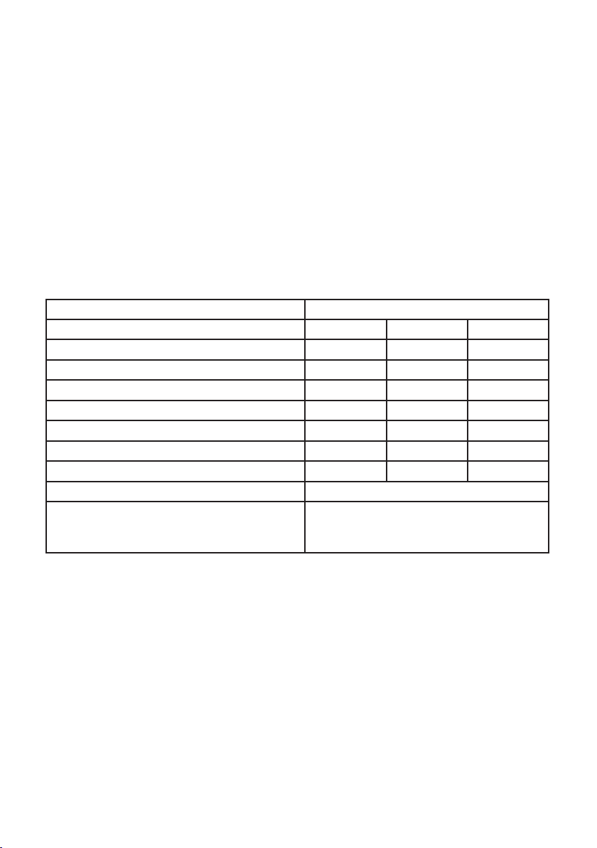
In the unlikely event of your Water Heater developing a fault, the following spare parts
are available:
Element plate assembly 1.2kW 95 606 901
Element plate assembly 3kW 95 606 981
Element plate assembly gasket (pk of ten) 95 611 021
Over temperature cut-out 95 612 050
Capillary thermostat 95 612 051
Control valve 95 605 855
Spout 95 604 010
Spout telescopic with adaptor 95 604 213
Terminal cover 95 614 267
Top cover moulding 95 614 265
Adaptor pusht 95 607 953
Adaptor long 95 607 954
Adaptor o-ring 95 607 955
Fixing fork 95 607 956
GUARANTEE
The Manufacturer will make good, by repair or at his option by replacement, defects
which, after proper installation, appear in the goods, within a period of 24 calendar
months after the goods have been delivered and arise solely from faulty design,
materials or workmanship. Provided always that defective parts are promptly returned
by the User free to the Manufacturer’s works, unless otherwise arranged, the repaired
or new parts will be delivered by the Manufacturer free of charge.
Provided further that in respect of parts or components not of the Manufacturer’s
manufacture, he will give the user a guarantee (if any) which the Manufacturer may
have received from the supplier of such parts or components in respect thereof, but not
so as to impose on the Manufacturer of such parts or components a liability greater than
imposed on him by the preceding paragraph.
Save as aforesaid the Manufacturer shall not be under any liability in respect of defects
in goods delivered or for any injury, damage or loss resulting from such defects, and his
liability under this guarantee shall be in lieu of any warranty or condition implied by
law as to the quality or tness for any particular purpose of such goods.
This guarantee in no way affects the statutory rights of the consumer.
The policy of Heatstore is that of continuous improvement and development, therefore
the right is reserved to change specication without notice.
ENVIRONMENTAL INFORMATION
Heatstore products are manufactured from many recyclable materials.
At the end of their useful life they should be disposed of at a Local Au
thority Recycling Centre in order to realise the full environmental ben
This manual suits for next models
2
Table of contents
Other Heatstore Water Heater manuals
Popular Water Heater manuals by other brands

Rinnai
Rinnai HJ Cooper LCUS00934010 Owner and installer guide

Bock Water heaters
Bock Water heaters 80030 brochure

Kenmore
Kenmore POWER MISER 9 153.337163 owner's manual

Rinnai
Rinnai INFINITY installation guide

Noritz
Noritz proTOUGH NR981-OD Replacement

STIEBEL ELTRON
STIEBEL ELTRON SBB 600 WP SOL Operation and installation