Heiland electronic TRD 2 User manual

B&W-Densitometer
Usermanual
Version 6.2
Heiland electronicGmbH
TRD 2

2
TableofContents
1. GENERAL INFORMATION.....................................................................3
2. SAFETYREGULATIONS.......................................................................3
3. AREAOF APPLICATIONS.....................................................................3
4. INSTRUMENT DESCRIPTION
4.1. STANDARDVERSION(FIGURE1)......................................................4
4.2.OPTIONS(FIGURE2,3)......................................................................6
5. INSTALLATION
5.1. LOCATIONCONDITIONS...................................................................8
5.2. SWITCHINGON..................................................................................9
6. READING
6.1. INSTRUCTIONSTO AVOIDINCORRECT READING..........................9
6.3. INSTRUCTIONSFORRESETTOZERO...........................................10
6.4. DENSITYMEASUREMENT...............................................................11
7. CAREOFINSTRUMENT......................................................................12
8. CALIBRATIONCHECK........................................................................12
9. GUARANTEE.......................................................................................13
10.TECHNICAL DATA.............................................................................14

TRD 2USERMANUALVersion 6.23
1. General information
DearCustomer,
thankyouforpurchasing aHeilanddensitometer. Inordertobecome
familiarwiththeoperationofyourinstrument, pleaseread these
instructionscarefullyandcompletelybeforeyourfirst use.
The packagingof theinstrumentisshock-absorbentandshouldbe
kept forthecaseof shippingandrepairs.
Useonlytheoriginalpackaging fortransportationandshipment. First
laythecardboardon thesurfaceofthebaseunit, thenplacetheroll
ofbubblefilmbetweenmeasuringhead andbaseunit.Finallyput the
instrument insidethe plasticbagand then intothe shipment-box.
Don't forget the calibrationstrips!
CAUTION:
Neverusetheremovablemeasuring head(Opt. 01)forcarrying
theinstrument. Thebaseunitmayseparateanddrop off!
Damagescausedbythisarenotincludedbyguarantee.
2. Safetyregulations
§Assurethatthemainvoltage and thefrequency onthe power
supplyunit isthesameastheone indicatedon theidentification
labelofthepowersupplyunit
§It isnotpermittedtoexchange thepowersupplyagainst another
onewithout the permissionofthemanufacturer.
§Always keeptheinstrument andthepowersupplyinadryplace
andneverimmerseit inanykindof liquid.
§Topreventelectricshock donotopen,neitherthedensitometer
northepowersupply. Therearenouserserviceablepartsinside.
3. Area ofapplications
The densitometerisdesignedforthe measurementofdensityvalues
ofB&Wandothernearlygreycolouredsubjects.The readingis
possibleinunitsoflogarithmicdensity.Pleasecontactthe
manufacturer,ifyou liketousetheinstrumentforotherapplications.
The modularconstructionoftheinstrumentenablestheuserto
optimiseit accordingtohisrequirements.
4
4. Instrumentdescription.
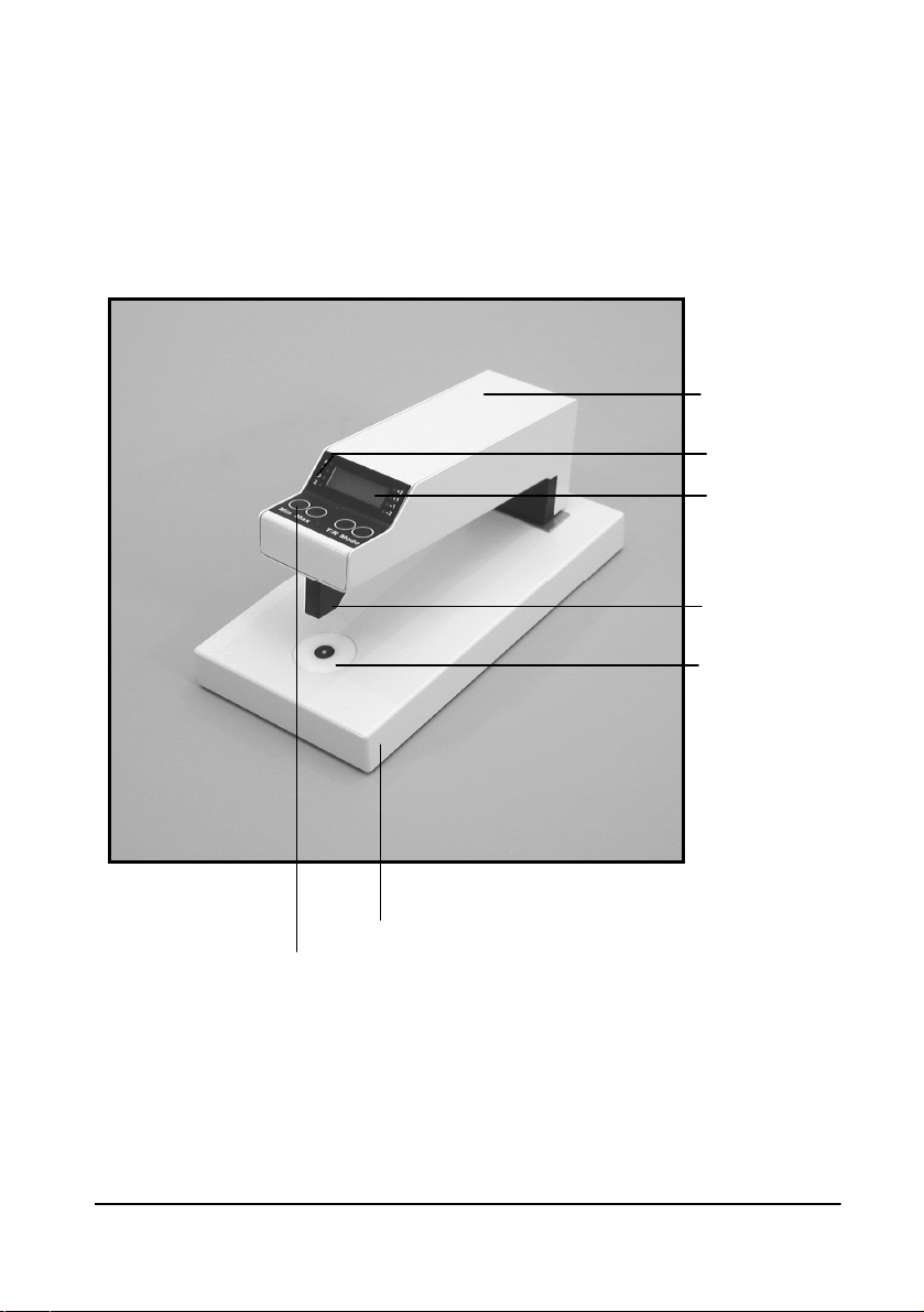
Figure1, TRD 2standardversion
Measuring
head
Mode-LED‘s
Mode and
reference
buttons
Probe
Aperture
Baseunit
Display

TRD 2USERMANUALVersion 6.25
4.1Standardversion
§The id-labelislocated onthe bottomof thebaseunit.
§The baseunitcontainsthetransmissionlamp. Thelight isemitted
throughanopalaperture.
§The topof the baseunitservesasaplatform, onwhichthefilmor
photorestsduring measurement.
§The measuringarm ismountedtothebaseunit byaprecise
bearing.Theintegrated springpushesthemeasuring head inthe
upperposition.Theheadcontainsthe sensingelectronic,below
ofittheprobeandthe reflectivelamparemounted.
§Oneof thelampsandthedisplays areautomaticallyactivated
whenthemeasuringheadislowered.
§The 3-digitdisplayallowsaprecisereadingdownto0.01log.D.
Ifthe minimumsensitivityofthesystemisreached orifthe
measuring headisdepressedtoofast, thedisplaywill flash
"-888". Ifreading alowerdensitythanat reset, anegativesignwill
appear. If thedisplayflashesEXX(whereXXisthe numberof
theerror) pleaseconsult themanufacturer.
§The LED'sbesidethe3-digitdisplayshowthe selected
measurement modewhilethemeasuring arm islowered.
T: Transmission measurement
R: Remissionmeasurement
D: Densityvaluesaredisplayed
§The switchesonthetopofthemeasuringarm areonlyactive,
whenthedisplayison.
The Minswitchsetsthe displaytozero,with
T/Ryouswitchbetweenremissionandtransmission mode.

6
Figure2, Rearsideand options
Opt.02
Opt.03
Opt.01
PowerSupply
TRD 2USERMANUALVersion 6.27
4.2Options
Option 01:Removablemeasuring head
The removedheadisusedforreflectionmeasurementonly! The
measuring head, whenattachedtothebaseunit ortheadditional
baseplate, iskept incorrectalignmentonly,whenthescrewwiththe
black knobon therearsideistightened. Formeasurementoflarge
muralsthe headiseasilyremovedfromthebodyandthenattached
toabaseplatewithanintegratedtarget. Theelectricalconnectionis
madewithalongorashortcable.
Measuring largeprints:
§Turntheinstrument so, that the longside isrightinfrontofyou.
§Removethecablebetweenthe baseunitandthemeasuring
head.
§Loosenthe screwon therearsideof theinstrumentbyturningthe
black knob.
§Gripthebackpartofthemeasuringheadindirection "A".
§Pull the measuringheadindirection"B"off thebaseunitandstick
it ontotheadditionalbaseplate.Keep attentionthat thevertical
partofthebaseplateslipsintotheslotofthemeasuring head
(betweencaseandbear).
§Tighten thescrewwiththeblack knob. Useno tool.
Ifyouattachtheheadtothebaseunit lateronpleaseconnect the
cableagain,otherwisethetransmissionlampwill notwork.
Figure3:Moving the
measuring head B
A

8
Option 02:Changeableapertures
The apertureshave4differentdiameters(0.5/1/2/3mm). Likethe
standarddiffusertheyaremadeout of opalmaterial. Smaller
diametersreducetheamountoflight,thusthemaximumdensityis
lowered. The apertureischangedbypressing slightlyontheedgeof
thediffuser, e.g.withthefingernail.Afterchangingtheaperture,new
referencepointsmustbesetfortransmissionmode.
Option 03:PCport
ToconnectthedensitometertoaPC,usetheoptionalUSBconnector
andcable. Seeappendixfordetails.
Option 05:Extendedtransmission densityrange
The maximumdensityintransmissionmode isextendedto5,5log.D.
Option 06:
The resolutionof the instrument isincreasedto0.001log.Dinthe
measurement rangebetween–0.999and+0.999log.D.
5. Installation
5.1Locationconditions
§Storeandusethisinstrumentonlyinroomswithatemperature
from17°Cto27°C(degreeCelsius)and relativehumidityfrom0
to70 percent.
Fast temperaturevariationsmaycausecondensation insidethe
densitometerorthe powersupply. Aftermovingtheinstrument
fromacoldtowarm environment (morethan10°Ctemperature
difference)pleasewaitat leastonehouruntil youconnectthe
powersupplyagain.
§Keepthedensitometerawayfromtheseenvironment:
-Direct Sunlight
-Instrumentsthatemitheat
-Aggressivechemicalsorliquids
-Strongmagneticfields,e.g.fromtransformers, voltage
stabilisersorloudspeakers
-Electronicdevicesthat emitstrong interference’s, likedimmers

TRD 2USERMANUALVersion 6.29
5.2Switchingon
§Assurethatthemainvoltage of thepowersupplyunit isthesame
asthe oneindicatedon theidentification labelof thisunit.
§Connectthepowersupplyfirst tothe densitometerandtheninto
thewall plug
§The instrumentswitcheson automaticallyinastand bymode.
Waitatleast2minutesbeforetakingthefirst reading.
.
6. Reading
Caution:Alwaysdepress the measuringheadsoftlyuntil it stopson
thereading-area.
Topreventdamageof the precisebearing,alwayslet themeasuring
head returnslowlytothe"up"position!Nevertrytoraiseithigher
thanthisstopposition!
Onadigitaldisplay,theactualvaluemayintermitbetweentwo
values. The displaychangingbackandforthbetweentwovalues
shouldnot beacauseforconcern.
6.1Instructionstoavoidincorrectreading
§Especiallywhenmeasuringhighdensitiesthesubject mustbe
free fromdust, lint,fingerprints, andothercontaminants.
§The right readingmode isveryimportant: "Transmission"forfilm,
glass platesorfilters. "Reflection"fornon-transparentsubjects
(i.e. pictures)Thewrongmodecausesconsiderableerrors.
§The densitometercanalsobeused forprocess controlwithB&W
imagesoncolour-basedfilm(i.e. silver-freefilms),if nocolour-
extractingfilterisrequired.
§Thick glass platesorfiltersshouldberead inlowambient light
becauseoftheirlight conductingtendency.
§Filmsshouldbe placedonthe readingarea withthe emulsion
side down.

10
6.2Instructionsforreset tozero
Resetthedisplaybeforestartingaseriesof densitymeasurements. If
thepart of the subjectused forzeroingdoesnothavethelowest
density,anegativesign will appearwhilemeasuring lowerdensity.
Reset of transmission reading
§Inphotographicapplicationsyoumaydecideeithertomeasure
thedensityinrelationtotheabsolutelightortobase+fog. Thatis
an unexposed,butadevelopedareaoffilm.
-Ifyouzerotoabsolutelight(nofilminthelight pass), the
base+fog isdisplayedwithapositivevalue andthisvaluehasto
be subtractedfromall densityvalues.
-Ifyouzerotobase+fog, the densityvaluesofanyareawithinthe
negativecouldbereaddirect. The absolutevalueofbase+fog
couldalsobemeasured, whiletakingareadingtoabsolutelight
andignoringthenegativesigninthiscase
§Ifinthick glassplatesorfilterszeroingtothelightsourceis
required,then thesubject tobe readmust beplaced onthe
reading areasothatthelight sourceisnot coveredup,but the
measuring headrestsonthe platewhenthemeasuring headis
depressed.Thefreelightfluxisequivalent toabsolute-zero.
Reset of reflectivereading
§Thereisnototallyreflectiveand diffusingmateriali.e. thereisno
absolutewhite.Bariumsulphateisusedforzeroing,becauseit
reflectsupto99%of diffuseincident light,however, it isalso
sensitivetosoiling anddamage. Normally, the backofafibre
based paperissufficientforzeroing.
§Inphotography, zeroingisdoneonthebasefog, thatisan
unexposedbutdeveloped partof the subject.
§Ifoccasionallymaterialthickerthan2mm istobe measured,then
thematerialandthepaperusedforzeroingshouldbeplaced
underthemeasuringheadtogethertoallowfortheoffset inthe
reading geometry. Thishint can beignored, if you'reworkingwith
theremovedmeasuringhead(Opt.01).

TRD 2USERMANUALVersion 6.211
6.3Densitymeasurement
Transmission reading
§Ifthe instrumentisnot inmode'T'select thismodebypushing the
"T/R"button.
§Resettozeroonbasefog.Positionfilmsothatthelightest part is
centred overthelight source. Depress measuringhead andpress
"Min"buttonuntil displayreads0.00.
§Measurement isdonebyslightlyloweringthemeasuring head
until light comeson,then centringtheareatobereadoverthe
light sourceandreadingthevalue withthefullydepressed
measuring head.
Reflectivereading
§Ifthe instrumentisnot inmode'R' select the modebypushing the
"T/R"button.
§Placesubjectinawaythattheareatobereadiscentred under
thetipofthemeasuring head. Press "Min"-button until display
reads0.00.
§Takeseriesofreadings.

12
7. Careofinstrument
§The housingandespeciallythe readingarea shouldonlybe
cleanedwithalightlydampenedsoftclothorchamois, if
necessarywiththeaddition of amildcleaner
§Donotusesolventsorabrasivematerials.
§The measuringheadandprobeshouldonlybecleaned fromdust
withasoft brushorcompressedair.
§Unplugtheinstrument whennot inuseforlongtimeperiods.
§Fornecessaryrepairssendthedensitometerandthepower
supplyunit tomanufacturerorauthorised servicecentre.Any
unauthorised opening,will invalidateyourguarantee.
§CAUTION:Topreventanelectricshockdo notopenthe
instrument!Thereareno userserviceablepartsinside!!
8. Calibrationcheck
The instrumentiscalibrated atthefactory. Certificationisshipped
withthe instrumentintheform ofatransmission and areflectivelight
calibration stripon whichthedensityvaluesof thecalibration are
recorded.
Note: The densitometerandthecalibrationstripsshippedwithit
belongtogether. Sincemeasuringgeometrymaydiffer,thecalibration
stripsshouldnotbeusedtocheck anotherdensitometer.
The calibrationstripsaremadeofphotographicmaterial.Theyshould
be kept inadark,cool,dry,anddust-free placetoprotectdensity
values. Donottouchreadingarea withbarehands. Soiledreading
areascauseincorrect readings, especiallyonhigh densities.

TRD 2USERMANUALVersion 6.213
Calibratingshouldbedoneunderthefollowingconditions:
§Ambient temperature20to22°Celsius.
§Relativehumiditybetween 0and70%
§Voltageandfrequencymustbeintolerancetothe oneindicated
on identificationlabel.
§The instrumentshouldbeacclimated toambientconditionsand
havebeenconnectedtothepowersourceforaminimumof 5
minutesbeforecalibrating.
§Forcalibratingprocedureusetheaperturewith3mm diameter
(Opt.02 only).
§Positionthecalibrationstripso, that the left field(0,00)of it is
centred overthelight source. Reset the displaytozero.
§Readingof densitiesisdoneinthecentreof eachtestarea. Ifa
slightdriftingofvaluesisencountered, the valuesshouldbe
averaged.
§The toleranceis±0.02 log. D. Ifgreatervariationsare
encountered,the TRD andthecalibrationstripshouldbesentto
themanufacturer,orauthorisedservicecentre, sinceanew
calibration isnotpossiblewithoutthenecessarytesting devices.
9. Guarantee
Thisinstrument isfullyguaranteed fortheperiodof one yearfrom
dateofpurchase.Proof of purchaseisthe invoiceorreceipt.
Damagesduetoimproperhandling orunauthorisedaccess are
excluded.
Thisinstrumenthasbeencarefullymanufactured andtestedusing
defectfreematerialsandstate-of-the-arttechnology.
Incaseof afailurethe instrumentshouldbereturned freeof charge
tothemanufacturerorauthorisedservicecentreaccompaniedby
proof of purchase.
Forthewarrantedperiod,the manufacturerwill paycostof
replacementpartsand repair. However,themanufacturerreserves
therighttoexchangetheinstrument. Important: Boththeinstrument
andcalibrationstripsmust besendbacktogether!

14
10.Technicaldata
§Dimensionslengthxwidthxheight: 200 x100x100mm
§Weight: 1kg
§Voltagerequirements: 12VDC byuseof awall
plugpowersupply
§Powerconsumption : 3VA
§Aperturediameter: 0,5/1/2/3mm
accordingtotheorder
§Readinggeometry
Transmission : diffuse/directed
Reflection: 45/0degrees
Opt.04: polarised
§Maximumsubjectsize
WidthxHeight: 260 mm x2mm
Opt.01 : 2mRadius
§Maximummeasurabledensity
Transmissionaperture. ∅3,0mm: 4,0D
∅2,0mm: 3,5D
∅1,0mm: 3,0D
∅0,5mm: 2,5D
Transmission Opt. 05: 5,5D
Reflection : 2,5D
§Readingvariation: ±(1%+0,02log.D.)
§Repeataccuracy: ±0,01D
§Temperaturerange : 17... 27°C
§Relativehumidity: 0... 70%
§Accessories: Powersupplyunit
Twocalibrationstrips

TRD 2USERMANUALVersion 6.215
Appendix: Communicationparameters
§Communicationport type: USB2,emulatingaserialcomportwith
9600 Baud, 8Databit, 2Stopbit.
§Characterwhicharesendtothedensitometerareansweredwith
thecharacterNAK(15h).
§The measurement valueistransmittedautomaticallybythe
instrumenteverytimethereisastablevalueforatleast0,5
seconds. Thevalueistransmittedwiththefollowingsyntax:
Character-No.possibleChar.meaning
1T/R/0Trans./Refl./StandBy
2+/-Sign
30...9/.ValueMSB
40...9/.Value
50...9/.Value
60...9/.ValueLSB
7D/Z/%Density/Zone/Percentage
ofdotarea
8CR Endof string
Examples:
T+1.53DTransmission
Density:+1.53logD
R-0.05DReflective
Density:-0.05logD
T+05.7ZTransmission
Zone:5.7
R+45.0%Reflective
45 Percentof dotarea
T+.278DTransm. incaseofOpt.06
Density:+0,278logD
0+....DStandBymodeor
measuring headisup
Issue date: January2007
Technicaldatamaychangewithout notice.

Table of contents
Other Heiland electronic Measuring Instrument manuals

Popular Measuring Instrument manuals by other brands


E Instruments
E Instruments E8500 Plus instruction & operation manual

Arizona Instrument
Arizona Instrument JEROME 431-X Operation manual

Mercury
Mercury 429.859UK user manual

Acrel
Acrel AMC Series Installation and operation instruction

LaserLiner
LaserLiner ClimaData Stick manual

Seametrics
Seametrics iMAG 4700 instructions

KROHNE
KROHNE OPTIMASS MFC 300 Handbook

ENCARDIO RITE
ENCARDIO RITE ESM-12S user manual

PCB Piezotronics
PCB Piezotronics 3501B1220KG/-0001 Installation and operating manual

Emerson
Emerson Rosemount 3812 Maintenance and troubleshooting manual

Anritsu
Anritsu MP1570A Operation manual

Bushnell
Bushnell YARDAGE PRO LEGEND instruction manual