Heiniger Acutecc Euro Grinder User manual

719-301 (EURO)
719-302 (GB)
Euro Shearers
Grinder
Manufactured by
H E I N I G E R A U S T R A L I A
F0262 Acutecc Euro Grinder Manual
1
22/09/2006
Rev:01

Contents
1.
General information
1.1
Motor specification sticker
1.2
Intended use
1.3
Contact addresses
2.
Safety regulations
2.1
Essential operator skills
2.2
Proper use
2.3
Power supply connections
2.4 Further measures for avoiding accidents
2.5 Residual dangers
2.6 Information symbols
3. Technical data
Technical data
Thermal overload
Equipment Items
Component list
Spare parts list
Discs & Pendulum
4. Guarantee
Introduction
Guarantee period
Guarantee conditions
5. Accepting delivery
6. Transporting
7. Initial start-up
8. Assembly
Assembly
Euro guards
Fitting the discs onto the grinder
9.
Grinder operating instructions
9.1
Setting up or adjusting the grinder to grind combs
9.2
Setting the length of the pendulum for combs
9.3
Grinding combs on the disc
9.4
When is the comb sharp?
9.5 Setting up or adjusting the grinder to grind cutters
9.6 Setting the length of the pendulum for cutters
9.7 When is the cutter sharp?
10. Emery setting procedure for Heiniger discs and double sided clamp plate.
11. Maintenance
12. Trouble shooting
13. Material groups
14. Component illustration
15. Spare parts illustration
16. Warranty registration card
F0262 Acutecc Euro Grinder Manual
2
22/09/2006
Rev:01

1. General information
1.1 Motor specification sticker
1.2 Intended use
The Heiniger Acutecc Shearers Grinder is designed for sharpening combs and cutters
for use on mechanical shearing handpieces.
It is to be used in conjunction with other equipment designed for this sharpening process.
All other uses are expressly prohibited.
1.3 Contact addresses
Heiniger Ltd
Industrieweg 8
PO Box CH-3360
Herzogenbuchsee Switzerland
T: +41 (0)62 956 92 00
F: +41 (0)62 956 92 81
E: kontact@heiniger. com
W: www.heiniger.com
Heiniger Australia PTY LTD
5A Tayet Link
Bibra Lake WA 6163
T: +61 (0)8 9434 0000
F: +61 (0)8 9434 0011
E: mail@heiniger.com.au
W: www.heiniger.com.au
F0262 Acutecc Euro Grinder Manual
3
22/09/2006
Rev:01
2. Safety regulations
2.1 Essential operator skills
The owner/manager of the grinder has an obligation to ensure that the operator is
competent to use the grinder.
Operating the grinder safely only makes small demands of the operator. However, it is
essential that they are observed and carried out.
The operator must have read and understood the manual or have been instructed in
the operation of the grinder by a skilled person and have had the potential dangers
pointed out to him. The operator shall be able to demonstrate an understanding of the
grinder controls and the hazards associated with the grinder.
It is an offence to operate the grinder without the Euro guards fitted and in proper
working order.
2.2 Proper use
HEINIGER Australia has fitted this grinder with safety devices in accordance with
relevant regulations to protect the operator during use.
Should these safety devices become inoperable for any reason it is the responsibility
of the owner to ensure that it is repaired before further use.
The proper use of the grinder is described in 9. Grinder operating instructions
The proper set up of the grinder is described on the wall chart that is supplied with this
grinder and in this manual at 9. Grinder operating instructions.
The details in 3. Technical Data, count as mandatory operating limits and ratings.
2.3 Power supply connections
The voltage specified on the makers sticker and in this manual and that of the local
power supply must match. The grinder may only be connected to an AC power supply.
In the event that the grinder is operated from a generator, the supply voltage must not
exceed that specified on the motor specification sticker.
Never plug the grinder into damaged sockets.
Observe the relevant regulations applicable in your country.
Completely unroll the power cable before plugging in.
Maintenance and cleaning of the grinder should only be carried out when the grinder
is not plugged in. When this is not practicable, greater care needs to be taken with the
grinder.
2.4 Further measures for avoiding accidents
The operating instructions must be kept safely and accessible at all times.
The disc guards must remain in place at all times unless
performing maintenance, in which case
the grinder must be unplugged from the power source.
Never use the grinder on an unsafe or unstable stand, pedestal or bench.
Never use the grinder with loose fitting clothing.
Always ensure adequate working room around the grinder.
Unauthorized persons are not permitted to use the grinder.
Unauthorized persons are not permitted
in the vicinity of the grinder when it is being operated or
maintenance is being carried out.
Never leave the grinder until it has completely stopped.
Ensure that the power cord is suspended to avoid accidents.
Never leave the grinder unsupervised when connected to the power
Avoid kinks and tight coils in the cable when storing, this can damage the cable.
Store the grinder in a dry undercover area when not in use.
Avoid getting electrical components of the grinder wet.
Never use a grinder or any part of a grinder, i.e. discs, pendulum when it is worn or damaged.
F0262 Acutecc Euro Grinder Manual
4
22/09/2006
Rev:01
Any damage or failure to the grinder which may constitute a risk to the health and safety
of any person shall be immediately reported by the operator to the owner/manager who
shall take appropriate action.
Examples of the type of damage, which would constitute such a risk include:
Frayed or damage insulation on electrical wiring.
Failure or wear of any control or component, i.e. switch, discs or pendulum.
Damaged or loose fasteners, nuts, bolts, etc.
Discs that are damaged in any way.
Incorrectly or badly set emeries.
Missing or damaged guards.
2.5 Residual dangers
Should dangers and hazards occur during operation of the grinder that are not directly
related to grinding, we request that you inform Heiniger of this. This also applies to a
technical failure that causes a hazard.
2.6 Information symbols
Warning
Indicates a potentially dangerous situation. If preventative action is not taken death or
very serious injury could result.
Warning
Indicates a potentially dangerous situation. Take preventative action.
Note
Note, non-compliance with which can lead to operating malfunctions or damage.
Warning
Eye protection must be worn.
Warning
Hearing protection must be worn.
Illustration
This symbol, together with its number, refers to the relevant illustration at the end of the
manual.
3.
Technical data
3.1
Technical data
Designation
Shearing Grinder
Model
Acutecc Euro Grinder
RPM
2800 r.p.m.
Volts
240V
kW
1.1 kW
Amps
7.5 A
Hz
50 Hz
Duty
S2
Dimensions (operational)
H 770mm L 400mm W 430mm
Dimensions (folded down)
H 480mm L 400mm W 430mm
Motor shaft
1” (BSW or UNC, RH & LH)
Weight (operational)
40 kg
Weight (shipping)
62 kg
3.2 Thermal overload
The grinder motor is fitted with an internal thermal overload; if the motor overheats this
will automatically shut the motor off.
If this happens the red indicator light in the switch will remain on.
Note: If the grinder motor stops due to overheating, turn the motor off at the switch,
failure to do so will result in an unexpected start when the thermal overload has cooled
sufficiently.
F0262 Acutecc Euro Grinder Manual
5
22/09/2006
Rev:01

3.3 Equipment Items
Discs
Clamp plate
Pendulum
Bolt set
Safety Glasses
Grinding wall chart
Spanner
Acutecc Hollow Gauge
Ear plugs
Operators manual
Grinding radius gauge
3.4
Component list
1.
Electric motor
15. Disc collar
2.
Motor cover
16. Disc nut
3.
Motor side cover
17. Disc washer
4.
Foot
18. Motor shaft
5.
Switch plate
19. Guard spacer
6.
Switch
20. Spanner bracket
7.
Telescopic tube
21. Motor specification sticker
8.
Cross arm collet
22. Euro guard
9.
Cross arm tube nut
23. Guard bracket
10.
Pendulum hook
24. Handle
11.
Pendulum hook tube nut
25. Disc
12.
Pendulum hook collet
26. Clamp plate
13.
Cross arm
27. Bolt set
14.
Spanner
Note: 12. Component illustration is at the end of the manual.
3.5 Spare parts list
Part
Part number
Spare part illus
Disc set
719-010
8
Electric motor
719-311
4
Spanner
719-318
7
Euro guard
719-061
6
Foot
719-323
1
Pendulum hook set 719-324
2
Cross arm set
719-325
3
Switch
719-328
5
Handle
719-062
9
Note: 13. Spare parts illustration is at the end of the manual.
F0262 Acutecc Euro Grinder Manual
6
22/09/2006
Rev:01

3.6 Discs & Pendulum
The special light weight aluminium alloy discs and pendulum are precision tools and
when used in conjunction with this manual give the best possible edge on your gear.
With care they will provide you with years of service.
To protect the pendulum, always store and transport it in the supplied case, use it only
as instructed in this manual.
It is essential that the discs are not subject to abuse or neglect. Damage may occur that
will render the discs unusable.
Note: The discs may be hazardous if used in a damaged condition.
If discs become damaged they must be replaced.
Use only genuine replacement discs.
The discs are fitted to the grinder when dispatched and are protected by the Euro guard.
This is the best way to protect the discs when transporting.
When not fitted to the grinder the discs should be bolted to the clamp plate and
protected from knocks or being dropped.
Do not drop the discs or lean them against a wall.
Do not subject discs to rapid and extreme changes in temperature.
Do not use levering or striking tools to remove discs from the grinder.
Do not use excessive force to remove the discs from the grinder.
Do not use excessive force or tools to remove emery and glue from the disc.
Do not over tighten the bolt when setting emeries to the discs.
Do not damage the mounting shoulder on the rear of the disc.
Assemble and run the grinder as per this manual when received to ensure you have
received it in good condition. See 5. Accepting delivery & 8.2 Fitting the discs onto the
grinder
7

4. Guarantee
4.1 Introduction
Your HEINIGER Acutecc Euro Grinder was made by one of Australia's best known
shearing equipment manufacturers.
The HEINIGER name has been synonymous with quality manufactured shearing
equipment for 60 years. That is your best guarantee.
Your HEINIGER Acutecc Euro Grinder was manufactured specifically to sharpen
sheep shearing combs and cutters.
With a minimal amount of care, your HEINIGER Acutecc Euro Grinder will provide you
with years of excellent service.
4.2 Guarantee period
A global warranty covers your HEINIGER Acutecc Euro Grinder against faulty materials
and workmanship for 1 year from the date of purchase. HEINIGER dealers in more than
36 countries will honour this warranty. Ensure that the warranty card at the back of this
manual is completed and returned to effect warranty period.
4.3 Guarantee conditions
Grinder discs and clamp plate are not covered under this warranty, neither are
damage due to improper treatmentor lack of due care, accidents, normal wear or
claims for subsequent damages.
Servicing by personnel
not specifically authorized by HEINIGER renders the warranty
null and void.
To be valid the warranty certificate
must be completed, signed by the HEINIGER dealer and
bear the date of purchase.
In case of a warranty claim, the original invoice must be presented along with the grinder.
Notify your HEINIGER dealer immediately you have a problem.
HEINIGER dealers are responsible for any additional warranty they may give.
This warranty is subject to the regulations in force in the countries concerned.
5. Accepting delivery
All units are transported at the owner's risk.
Before accepting delivery, thoroughly inspect the Grinder for damage.
If any has occurred you should note the nature and extent of the damage in view of any
insurance claim you may wish to make.
Whilst all care is taken during manufacture and by our agents to ensure your grinder
arrives in perfect working order and condition, damage occurring during transit or
faulty operation resulting from damage occurring during transit will not be covered by
our warranty.
The following areas should be checked carefully:
The Euro guards; they should be located securely in place.
Electrical components, Discs and clamp plate, Pendulum.
6. Transporting
The grinder is supplied in a case; it is advisable to transport the grinder in this case
whenever practicable.
When moving the grinder in the case use only two adults or a suitable trolley.
When lifting the case use the case handles.
It is essential that the discs are protected in transit. If the discs are fitted to the grinder
whilst in transit they are protected by the Euro guards.
Lower the cross arm during transit.
If the grinder is to be transported not in the case, ensure that it cannot tip or slide.

8

7. Initial start-up
Note: Do not attempt to start the grinder unless this manual has been fully read and
understood.
Before starting the grinder ensure that the disc nuts are tight.
The on/off switch for the grinder is located on the front of the motor housing.
Ensure that the switch is in the off (up) position before connecting the grinder to a power
source.
Do not start the grinder unless the Euro guards are fitted and you are wearing safety
glasses.
Do not attempt to grind until the grinder is at full speed.
8. Assembly
8.1 Assembly
The Euro grinder is dispatched fully assembled, however it must be set up before being
used for grinding, for full setup instructions refer to 9. Grinder operating instructions
Note: The voltage specified on the grinder and that of the local power supply must match.
The grinder may only be connected to an AC power supply.
In the event that the grinder is operated from a generator, the power supply must not
exceed that specified on the grinder.
Note: When removing the grinder from the case use two adults and lift the grinder
as illustrated.
Loosen the two Cross arm tube nuts (9.) and lift the Cross arm (13.) to its full height. Re-
tighten the tube nuts while holding the Cross arm at its full height.
8.2 Euro guards
The Euro grinder is fitted with guards enclosing the discs to protect the user during
use. See 2.2 Proper use & 2.4 Further measures for avoiding accidents.
The Euro guards must remain in place at all times unless performing maintenance. It is
necessary to remove the outer part of the Euro guard to remove and refit the discs. The
outer part of the Euro guard is secured with three screws & nuts. When refitting the Euro
guards always use all three screws & nuts, tightened securely.
8.3 Fitting the discs onto the grinder
Note: Unplug the grinder from power before proceeding. The outer Euro guard on
either side must be removed to remove or fit a disc. The thread on the left-hand shaft is
left-handed. Always use the washer.
8.3.1 Slide the disc onto the shaft of the grinder, ensuring the collar on the shaft and the disc are
free from dirt, dust or any other foreign matter, tighten the disc nut.
8.3.2 Once both discs are fitted and tightened, check by placing a flat hand onto each disc and
try to move the discs in opposite directions. If either disc moves on the shaft the nuts are
not tight. Re-tighten and check again. Always refit the Euro guards.
Note: The discs fitted to the grinder have been individually checked for balance. It must be
noted that it is possible for the glue and/or the emery to throw the balance off, see 11.
Troubleshooting
9

9. Grinder operating instructions
Includes: Grinder setup, Grinding technique & using the Heiniger variable handle
adjustable pendulum
Warning:
Always ensure that the Euro guards are securely fitted before setting up and using the
grinder.
Ensure the emeries are stuck to the disc and have no air bubbles between the emery
and disc.
Ensure you have cut the excess emery from the disc leaving the edge smooth.
Always wear protective goggles and ear protection.
Ensure the disc nuts are tight.
The on/off switch for the grinder is located on the front of the motor housing.
Ensure that the switch is in the off (up) position before connecting the grinder to a power
source.
When the grinder is running do not allow anything to come into contact with any part of
the discs.
Do not attempt to grind until the grinder is at full speed.
Note: Before setting up the grinder, ensure that the cross arm has been lifted to its full
height and the tube nuts are locked.
9.1 Setting up or adjusting the grinder
to grind combs
With grinder turned off and the
pendulum with a comb in place
hanging from the pendulum hook,
push the pendulum towards the
grinding disc. Adjust the pendulum
hook in or out so the heel of the
comb hits the grinding disc first.
As the heel of the comb touches the
grinding disc, adjust the pendulum
hook in or out to make the tip or ball
of the comb to be 1.5mm (or a match
thickness) away from the grinding
disc. The grinder is now set (see fig
’A’).
10

9.2 Setting the length of the pendulum
for combs
Remove the comb from the
pendulum. With the grinder turned off,
hang the pendulum on the pendulum
hook. Place the Heiniger grinding
gauge on the pendulum comb pins
making sure that the smallest end of
the grinding gauge is nearest the
grinder shaft (see fig ‘B’). Then put
your comb on the comb pins.
Place the comb on the disc where
you will finish your grind, we suggest
towards the outside of the disc with
no teeth being off the disc (see fig
‘B’), then adjust the length of the
pendulum up or down until the long
red line on the gauge runs through
the centre of the motor shaft (see fig
‘B’). Then tighten the pendulum tube
nut. Remove the comb and the
grinding gauge from the pendulum.
The pendulum length is now set.
9.3 Grinding combs on the disc
Holding your pendulum with the knuckle of your index finger directly under your thumb,
(see fig ‘C’) land your comb onto the disc. Using very firm pressure grind from side to
side taking the outside three teeth of the comb past the edge of the disc, then grind as
far to the very centre of the disc as possible, (see fig ‘D’). On a Heiniger grinder, grind
towards the grinder shaft until your comb touches the washer.
Move the comb side to side from three teeth off the disc to the centre with very firm even
pressure until the comb is sharp. Then on the last stroke move from the inside of the disc
to the outside, where you set the length of the pendulum (see fig ‘B’), and remove the
comb from the disc.
Note:
Always hold the pendulum on the pendulum hook with your spare hand (see fig ‘A’).
Use all the paper
(see fig ‘D’).
Take three teeth of the disc
(see fig ‘D’).
Use very firm even pressure.
On the last stroke, grind from the centreto the outside edge, where you set the length of the pendulum (see fig ‘B’), and not off
the disc.
9.4 When is the comb sharp?
The whole surface of the comb must be ground, especially where the cutter has been
cutting on the teeth. With good light, look carefully at the cutting edges of the teeth
and make sure there are no shiny or silver lines on the cutting edges of the tooth
once you have ground because these are blunt edges (see fig ‘G’).
11

The light will shine on a rounded/blunt edge but will not shine on a sharp edge.
Note: You must grind your combs until the blunt edge is sharp (see fig ‘f’). If in doubt,
grind it again.
12

9.5 Setting up or adjusting the grinder
to grind cutters
With the grinder turned off, hang the
pendulum from the pendulum hook.
Fit the cutter to the cutter pins and
lightly slide the cutter over the disc
a couple of times using the grinding
action (see fig ‘H’).
If the pendulum hook is too far in the
cutter will be rubbing on the tip (see
fig ‘I’), if the pendulum hook is too
far out, the cutter will rub on the heel
(see fig ‘J’). Adjust the pendulum
hook until the cutter rubs on both the
tip and heel (see fig ‘K’).
13

9.6 Setting the length of the pendulum
for cutters
Remove the cutter from the
pendulum. With the grinder turned off,
hang the pendulum on the grinder
pendulum hook. Place the Heiniger
grinding gauge on the cutter pins
making sure the smallest end of the
Heiniger grinding gauge is near the
grinder shaft (see fig ‘M’). Place the
cutter on the cutter pins on top of the
grinding gauge. Place the cutter on
the disc where you will finish your
grind, we suggest 25mm in from the
outside of the disc (see fig ‘M’), then
adjust the length of the pendulum up
or down until the long red line on the
gauge runs through the centre of the
motor shaft (see fig ‘M’). Then
tighten the pendulum tube nut.
Remove the cutter and the grinding
gauge from the pendulum. The
pendulum length is now set.
Grinding cutters on the disc
Holding the pendulum with the
knuckle of your index finger directly
under your thumb, (see fig ‘C’), land
your cutter on the disc. Using an even
moderate pressure, grind from side to
9.7 When is the cutter sharp?
Check that you have a slight burr on the
four tips of your cutter that move up or
down when you touch them (see fig ‘N’),
check that the whole surface of the cutter
is ground and there are no dull patches.
If in doubt, grind it again.
14
side, making sure you use all the
paper, by going from as far to the
outside as possible to as far to the
inside as possible.
Grind from side to side until the cutter
is sharp. Keeping the same pressure
on the cutter, on the last stroke move
from the centre to where you set the
length of the pendulum (see fig ‘M’),
then remove the cutter from the disc.

10. Emery setting procedure for Heiniger discs and double sided clamp plate.
10.1 Undo clamp plate bolt and nut using the grinder spanner.
10.2 Separate clamp, discs, bolt, nut and 2 washers.
10.3 Ensure discs and clamp plate are dry and completely free from any foreign matter. If
necessary clean discs and clamp plate only with warm soapy water and a scrubbing
brush, allow to dry.
Note: Do not use any form of petroleum based solvents when cleaning discs.
10.4 Place one of the washers on the clamp plate bolt. Place one disc over the clamp plate
bolt grinding side up.
10.5 On a table or bench place both discs grinding side up, place a towel or cloth underneath the
discs so as not to damage the boss or underside of the discs.
Note: Damaging the boss of the disc will create vibration when grinding.
10.6 Shake glue bottle vigorously. Apply glue to both discs around the middle of the face or
grinding side, use approximately 20 ml, and spread evenly using either a brush or the
palm of your hand coating the entire grinding side surface of both discs. In warm weather
we advise to work quickly or the glue may set prematurely.
Note: Do not use excess glue, using excess glue will cause the emery to lift or
bubble between the emery and the disc face.
10.7 While the glue is still wet place either a coarse (40 grit) or fine (80 grit) emery, smooth side
down over the protruding clamp plate bolt and let the smooth side of the emery rest on the
glue.
Note: Do not spin or twist emery on the glue this will cause bubbles or lifting.
10.8 Place the clamp plate over the protruding clamp plate bolt and let it rest on the emery.
Note: Do not place any other material between emery and clamp plate eg: rubber or
newspaper.
10.9 Place another emery either coarse (40 grit) or Fine (80 grit) over the protruding clamp plate
bolt, rough or grinding side down and let it rest on the clamp plate.
10.10 Place the other disc over the protruding bolt glue side or grinding side down and let it rest
on the emery.
10.11 Place the other washer over the protruding clamp plate bolt followed by the clamp plate nut;
tighten with the grinding spanner.
Note: Do not tighten the nut by hitting the grinding spanner tight with another object, tighten
the grinding spanner only with your hands.
10.12 If emeries are square and not pre-cut round, trim excess emery around the clamp plate.
10.13 Allow to set for a minimum of 1 hour.
10.14 Separate discs and clamp plate carefully and leave to completely dry before use a minimum
of 1 hour.
Note: Heiniger double-sided clamp plates must have 2 discs to clamp effectively even if
only one emery is being set at a time.
15

11. Maintenance
Use only genuine or equivalent specification replacement parts.
All parts are available through Heiniger dealers.
Use only qualified personnel for electrical repairs.
Always contact an authorized service centre if you are unsure how to rectify a problem or in
the event of malfunctions not contained in this manual.
Only perform maintenance when the grinder is disconnected from the power.
Electric motor
Periodically remove an outer Euro guard and disc and use dry compressed air to blow any
dust build up from inside the plastic electric motor cover and on the motor. Failure to keep
the motor dust free may reduce the cooling ability of the motor and cause it to cut out due to
overheating. See 3.2 Thermal overload
Do not disturb the collars fitted to the motor shaft, if they are moved they must be
refitted and trued to the shaft by qualified personnel. Failure to do so may cause
vibration. Keep the motor shaft, collars, disc nuts & washers clean and dry at all times, if
required clean with a little kerosene and dry thoroughly.
If the grinder is to be stored use anti rust on the shaft and collar, ensure this is cleaned off
before using.
Periodically check the condition of the power cord, replace if worn or damaged.
Foot
Ensure that feet are fitted and secure; failure to do so may lead to the grinder becoming
dangerously unstable.
Switch
Ensure the silicone boot covering the switch remains intact and in place. Failure to do so will
shorten the life of the switch. Replace damaged switches immediately.
Pendulum hook
If the pendulum hooks are damaged replace them before the grinder is used.
Cross arm
Periodically remove the Cross arm assembly and clean any dust or grease from inside the
tube nuts and collets and the thread on the telescopic tube.
Euro guard
The grinder is fitted with Euro guards that enclose the disc; these guards are integral to the
safe use of the grinder. At all times maintain the guards in correct working order, they must
fit the grinder correctly and securely. In the event of damage they must be repaired or
replaced before the grinder is used. When fitting the outer Euro guard to the grinder ensure
a new comb will fit between disc and guard without touching both disc and guard.
Discs
Keep the steel boss in the centre of the disc dry and free of dirt and grease.
If the discs are to be stored use anti rust on the boss. Ensure this is cleaned off before
using. Ensure that no anti rust gets on the face of the disc.
It is essential that the discs are not subject to abuse or neglect. Damage may occur
that will render the discs unusable.
Note: The discs may be hazardous if used in a damaged condition.
If discs become damaged they must be replaced. Use only genuine Heiniger replacement
discs.
The discs are fitted to the grinder when dispatched and are protected by the Euro
guard. This is the best way to protect the discs when transporting.
When not fitted to the grinder the discs should be bolted to the clamp plate and
protected from knocks or being dropped.
Clamp plate
The clamp plate must be protected from damage as the discs are.
Pendulum
Refer to the pendulum manual for maintenance instructions.
16
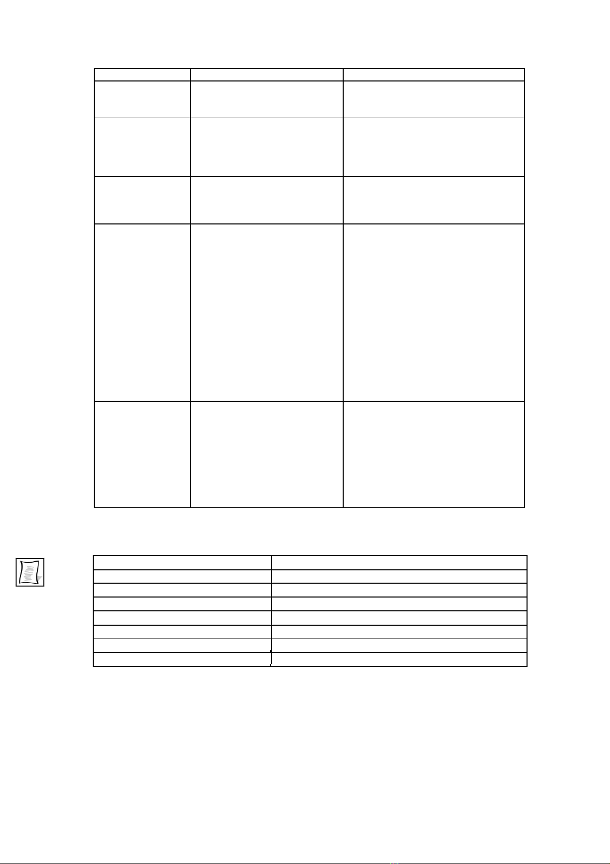
12.
Trouble shooting
Problem
Cause
Solution
For all electrical faults qualified
persons only may undertake fault
finding and repairs.
Motor doesn’t
No power.
Check the plug is correctly connected
start, switch light
to the socket.
is off.
Check that power is available at the
socket.
Call an electrician.
Motor stops,
The motor has overheated and
Allow the motor to cool. Note: When
switch light is on.
the internal thermal overload
the motor has cooled sufficiently if
has cut out.
the switch is still turned on it will
restart without warning.
Grinder vibrates.
Discs out of balance.
1) Emeries not in centre of
1) Reset with emeries in the centre.
disc.
2) Clean discs in soapy water.
2) Discs have glue on the
back.
3) Reset emeries with even glue
3) Uneven glue spread under
spread.
emeries.
4) Remove discs clean collar and
4) Foreign matter between disc
disc and replace.
and collar on shaft.
5) Replace disc.
5) Discs buckled.
Emeries won’t
1) Wrong glue used.
1) Use Heiniger shearer’s glue.
stick to discs
2) Old glue used.
2) Use new Heiniger shearers glue.
3) Wash in hot soapy water.
3) Discs have film of foreign
matter on them (oil, dirt,
grease, old glue etc).
4) Buy new disc or clamp plate.
4) Disc or clamp plate buckled.
13. Material groups
Please be aware of the relevant regulations applicable in your country when disposing
of discarded parts. Refer to 14. Component illustration
Material
Contained in position
Iron/steel
1, 3, 14, 15, 16, 17, 20, 22, 23, 24, 27
Aluminium
1, 7, 25, 26
Copper
1
Stainless steel
10, 13
Polyethylene
2
ABS
8, 9, 11, 12, 19
Rubber
4
17
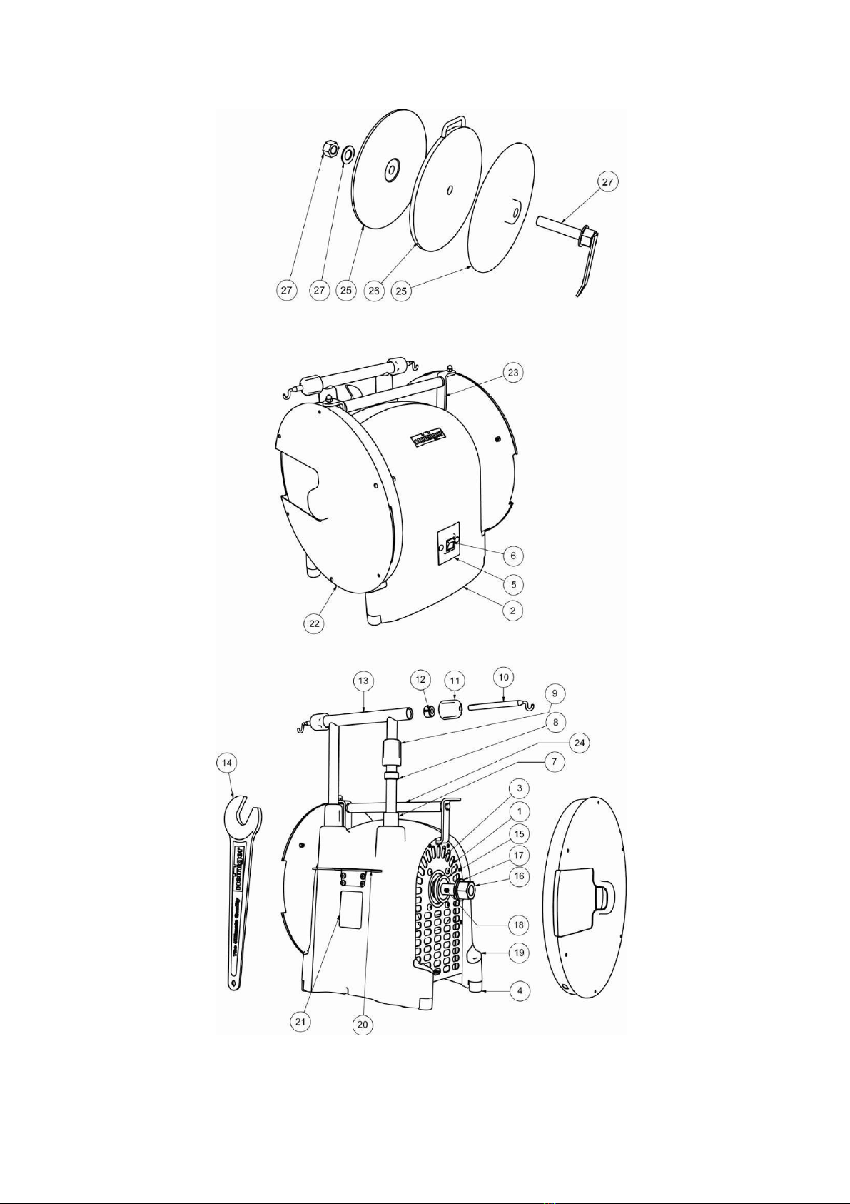
14. Component illustration
18

15. Spare parts illustration
19
Table of contents
Other Heiniger Grinder manuals


