Heinz Walz KF-24/6B User manual

COLD TRAP
and
TEMPERATURE CONTROLLER
KF-24/6B
KF-18/2B
MGK-1B
TR-KF-24
TR-KF-18
3rd Edition: August 2011
Coldtrap new-3.doc
©Heinz Walz GmbH, 2011
Heinz Walz GmbH •Eichenring 6 •91090 Effeltrich •Germany
Phone +49-(0)9133/7765-0 •Fax +49-(0)9133/5395


CONTENT
I
CONTENT
1Safety Instructions......................................................................1
1.1 General Safety Instructions......................................................................... 1
1.2 Special Safety Instructions.......................................................................... 1
2General.........................................................................................2
2.1 Transport....................................................................................................... 2
3Cold Trap KF-24/6B .....................................................................3
3.1 Installation..................................................................................................... 3
3.2 System Description ...................................................................................... 5
3.2.1 Design......................................................................................................... 5
3.2.2 Function...................................................................................................... 7
4Cold Trap KF-18/2B .....................................................................9
4.1 Installation..................................................................................................... 9
4.2 System Description .................................................................................... 11
4.2.1 Design....................................................................................................... 11
4.2.2 Function.................................................................................................... 13
5Mesuring Gas Cooler MGK-1B .................................................15
5.1 Installation................................................................................................... 15
5.2 System description..................................................................................... 17
5.2.1 Design....................................................................................................... 17
5.2.2 Function.................................................................................................... 18
6Temperature Controller TR-KF-24............................................21
6.1 System description..................................................................................... 21
7Temperature Controller TR-KF-18............................................24
7.1 System description..................................................................................... 24
8Operation ...................................................................................26
8.1 General......................................................................................................... 26
8.2 Virtual Keyboard......................................................................................... 27
8.3 Main Window............................................................................................... 28
8.4 Protocol & Status........................................................................................29

CONTENT
II
8.5 Temperature Set Value............................................................................... 29
8.6 Control Start / Stop..................................................................................... 30
8.7 Chart Settings ............................................................................................. 30
8.7.1 Touch Pen Options: Chart 2 and Chart 3................................................. 31
8.7.2 Graph Magnification.................................................................................. 31
8.7.3 Scale: Chart 1........................................................................................... 32
8.7.4 Scale: Chart 2 and Chart 3....................................................................... 32
8.8 Settings........................................................................................................ 32
8.8.1 Screen Brightness .................................................................................... 33
8.8.2 Temperature Regulation........................................................................... 33
8.8.3 Extern Value............................................................................................. 33
8.8.4 Graph........................................................................................................ 33
8.8.5 Dew-Point Calibration............................................................................... 34
8.8.5.1 Offset................................................................................................. 34
8.8.5.2 Calibration......................................................................................... 34
8.8.5.3 Factory Value.................................................................................... 35
8.8.6 Start-up Sequence.................................................................................... 36
8.9 Menu............................................................................................................. 36
8.9.1 System Value............................................................................................ 36
8.9.2 Protocol..................................................................................................... 37
8.9.3 Settings..................................................................................................... 37
8.9.4 Service...................................................................................................... 37
8.9.5 About........................................................................................................ 37
8.9.5.1 Program Update................................................................................ 37
8.9.5.2 Load Factory Values......................................................................... 37
8.9.5.3 ST-Control Update............................................................................ 38
8.9.6 PC OFF .................................................................................................... 38
9Accessories...............................................................................39
9.1 WLAN-USB Adapter for Remote Control.................................................. 39
10 Maintenance...............................................................................40
11 Pin Assignment and Fuses.......................................................41
11.1 Connectors of KF-24/6B............................................................................. 41
11.2 Connectors of KF-18/2B............................................................................. 41
11.3 Connectors of MGK-1B.............................................................................. 42
CONTENT
III
11.4 Fuses and Connectors of TR-KF-24.......................................................... 43
11.5 Fuses and Connectors of TR-KF-18.......................................................... 44
12 Technical Data ...........................................................................45
12.1 Cold Trap KF-24/6B..................................................................................... 45
12.2 Cold Trap KF-18/2B..................................................................................... 46
12.3 Measuring Gas Cooler MGK-1B................................................................. 47
12.4 Temperature Controller TR-KF-24............................................................. 48
12.5 Temperature Controller TR-KF-18............................................................. 48
13 Warranty Conditions .................................................................49


SAFETY INSTRUCTIONS CHAPTER 1
1
1Safety Instructions
1.1 General Safety Instructions
1. Read the safety instructions and the operating instructions first.
2. Pay attention to all the safety warnings.
3. Keep the device away from water or high moisture areas.
4. Keep the device away from dust, sand and dirt.
5. Always ensure there is sufficient ventilation.
6. Do not put the device anywhere near sources of heat.
7. Connect the device only to the power source indicated in the
operating instructions or on the device.
8. Clean the device only according to the manufacturer’s recom-
mendations.
9. Ensure that no liquids or other foreign bodies can find their way
inside the device.
10. The device should only be repaired by qualified personnel.
1.2Special Safety Instructions
The Cold Traps and Temperature Controllers are research
instruments which should only be used for purposes specified in
this manual. Please follow the instructions of this manual in
order to avoid potential harm to the user and damage to instruments.
CHAPTER 2 GENERAL
2
2General
The Cold Traps KF-24/6B,KF-18/2B, and the Measuring Gas
Cooler MGK-1B are suitable for cooling gas to a predetermined
dew-point, so that excess humidity condenses. In this capacity the
devices can be used in the following applications:
-Input control in gas exchange measuring systems
-Humidity compensation (bypass humidity control) in gas ex-
change measuring chambers
-Calibration of measuring devices for humidity determination
(e.g. dew-point mirror or humidity sensors)
Unlike the cold traps, which have one gas conduit, the measuring gas
cooler has two equal gas conduits in parallel for pre-drying a refer-
ence and a sample gas in gas analysis.
The cold traps and the measuring gas cooler require a temperature
controller for operation.
2.1 Transport
Before transport, any condensate has to be drained from the conden-
sate hose; otherwise some of the liquid may run into the gas conduit
of the cold trap, and may be pushed out unintentionally with the gas
flow.
Note: If condensate has entered the gas conduit of the cold trap
or measuring gas cooler, the device must be dried by
flushing it with air for approximately 30 minutes.

COLD TRAP KF-24/6B CHAPTER 3
3
3Cold Trap KF-24/6B
3.1 Installation
The Temperature Controller TR-KF-24 is required for the operation
of the Cold Trap KF-24/6B.
Fig. 1: Cold Trap KF-24/6B; left: Front side; right: Back side
1) Condensate hose with drain cock at the end
2) Gas IN and OUT
3) Connectors for cooling water
4) Connector for Temperature Controller TR-KF-24
5) Pt 100
The Cold Trap KF-24/6B may be operated indoors as well as in the
field. In the field, the user has to ensure that the device is sheltered
from the effects of the weather.
1
2
3
2
45
CHAPTER 3 COLD TRAP KF-24/6B
4
The cold trap must stand upright to enable the condensate to drain off
freely into the hose connected as condensate collector.
Note: The hose must hang free or be arranged so that it can be
filled with condensate, without forming air bubbles.
The collected condensate must be emptied before the hose is
completely filled up via the water drain cock attached to the end of
the hose. If there is some negative pressure in the cold trap,
which is the case if the gas is sucked through it by a gas pump, this
pump must be switched off before the cock is opened for draining;
otherwise, condensate might be sucked into the gas conduit of the
cold trap and enter the downstream measuring system. If the cold
trap is under slight overpressure there is no such risk.
The cold trap must be positioned so that its fan can freely ventilate
the external heat exchangers. Do not cover the fan inlets and outlets.
In order to avoid over-humidification of the downstream
measuring system, the gas flow should only be turned on after
the set dew-point has been reached.
Each cold trap should only be operated with its own matching tem-
perature controller, because calibration values are stored in the tem-
perature controller.

COLD TRAP KF-24/6B CHAPTER 3
5
3.2 System Description
3.2.1 Design
Fig. 2: Cross-section through the Cold Trap KF-24/6B
1) Perspex inserts
2) Platinum temperature sensor Pt 100
3) Peltier elements
4) Heat exchanger for liquid cooling
5) Air heat exchanger
6) Condensate drain
7) Interior part
8) PU-foam
9) Fan

CHAPTER 3 COLD TRAP KF-24/6B
6
The interior part (7) of the cold trap KF-24/6B is thermostated by the
Peltier elements (3). It has two boreholes for the gas conduit. At the
lowest point of this gas conduit there is a condensate drain (6). The
condensate collects here and runs into the condensate hose.
The interior part consists of aluminium, which is anodized for surface
protection. If corrosive gases shall be applied, the inner part can be
manufactured of stainless steel on request. Two Perspex inserts reach
into the inner part. They serve as gas feeders. The Perspex inserts
have inside threads G 1/4", which accommodate hose fittings.
The Peltier elements are in contact with two heat exchangers for
liquid cooling (4) and two heat exchangers for air cooling (5). In
normal operation, the heat generated at the Peltier elements is dissi-
pated by air cooling. For an extended refrigerating capacity, the heat
exchanger (4) can be cooled with water or other cooling liquids.
In the middle of the interior part, two temperature sensors (Pt 100)
(2) are located. One of them acts as actual value sensor for the tem-
perature controller. It is connected to a measuring transducer, which
is mounted under a cylindrical cap at the side of the housing. The
measuring transducer supplies a voltage between 0 and 4.095V,
which is proportional to the measured dew-point in the range of
-50 to 70°C. The other Pt 100 is installed for control measurements.
It is connected to the two screw terminals located at the back side of
the housing.
The cavities between the housing, Peltier elements,and the interior
part are filled with polyurethane foam (8) to provide thermal insula-
tion.

COLD TRAP KF-24/6B CHAPTER 3
7
3.2.2 Function
The Temperature Controller TR-KF-24 is used to set the desired
dew-point temperature of the Cold Trap KF-24/6B. It supplies the
power to the Peltier elements in such a way that the temperature of
the interior part is adjusted to the set dew-point temperature.
Depending on the ambient temperature, the cold trap reaches the set
dew-point after a few minutes. Humid gas is passed through the inte-
rior part of the cold trap, where it cools to the set dew-point tempera-
ture. Condensate falls, collects in the bottom of the cold trap and runs
into the condensate hose.
If a dew-point is desired that is higher than the dew-point of the in-
coming gas, more humidity must be generated by using a gas wash-
ing bottle.
If a dew-point is desired that is close to or higher than the ambient
temperature, the outgoing hose must be heated. By heating the hose,
condensation cannot form inside. Unheated hoses should not be laid
on the ground, which is usually markedly colder than the ambient
environment, especially outside in the field.
If the cold trap operates continuously at dew-point temperatures be-
low 0 °C, the conduits will freeze depending on the flow rate and
humidity of the gas. To defrost the unit, switch off the controller.
Alternatively, the dew-point may be set to 10°C above ambient
temperature. The gas flow should be switched off during
defrosting.
CHAPTER 3 COLD TRAP KF-24/6B
8
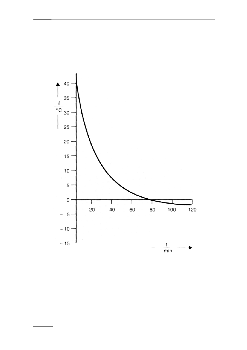
The diagram below (Fig. 3) shows the cooling time at ambient tem-
perature +40 °C down to -1 °C.
Fig. 3: Cooling time from +40 °C to -1 °C for a gas flow of 20 l/min
at 40°C ambient temperature

COLD TRAP KF-18/2B CHAPTER 4
9
4Cold Trap KF-18/2B
4.1 Installation
The Temperature Controller TR-KF-18 and the external AC Power
Supply 3020-N are required for the operation of the Cold Trap KF-
18/2B.
The Cold Trap KF-18/2B can be operated indoors as well as in the
field. In the latter case the user has to ensure that the device is shel-
tered from the effects of the weather.
1) Condensate hose with drain cock at the end
2) Gas IN
3) Gas OUT
2
1
3
Fig. 4: Cold Trap KF-18/2B

CHAPTER 4 COLD TRAP KF-18/2B
10
At the front side of the cold trap is a condensate hose with drain cock
connected. Also at the front side is the gas outlet (OUT). The gas
inlet is located on the top of the cold trap (Fig. 4).
A9-pin jack for the connection of the temperature controller is lo-
cated at the back of the housing beneath the fan.
The cold trap must stand upright to enable the condensate to drain off
freely through the condensate drain into hose connected as conden-
sate collector. For this purpose the rear feet are slightly higher
than the front ones to enable the condensate to flow forwards
into the direction of the condensate hose.
Note: The hose must hang freely or be arranged so that it can be
filled with condensate without forming air bubbles.
The collected condensate must be emptied before the hose is
completely filled via the water drain cock attached to the end of the
hose. If there is some negative pressure in the cold trap, which is
the case if the gas is sucked through it by a gas pump, this pump
must be switched off before the cock is opened for draining;
otherwise, condensate might be sucked into the gas conduit of the
cold trap and enter the downstream measuring system. If the
cold trap is under slight overpressure there is no such risk.
In addition, the cold trap must be positioned such that the fan can
ventilate the external heat exchanger. Do not cover the fan.
In order to avoid over-humidification of the downstream measuring
system, the gas flow should only be turned on after the set dew-point
has been reached.
Each cold trap should only be operated with its own matching tem-
perature controller, because calibration values are stored in the tem-
perature controller.

COLD TRAP KF-18/2B CHAPTER 4
11
4.2 System Description
4.2.1 Design
Fig. 5: Cross-section through Cold Trap KF-18/2B
1) Perspex gas connection
2) Gas outlet
3) PU-foam
4) Gas conduit
5) Condensate drain
6) Housing
7) Interior part
8) Peltier elements
9) Heat exchanger
10) Round jack
11) Fan
12) Temperature sensor Pt 100
13) Temperature sensor Pt 100

CHAPTER 4 COLD TRAP KF-18/2B
12
The interior part (7) of the cold trap KF-18/2 is thermostated by the
Peltier elements (8). It has two boreholes for the gas conduit (4). At
the lowest point of this gas conduit there is a condensate drain (5).
The condensate collects here and runs into the condensate hose.
The interior part consists of aluminium, which is anodized for
surface protection. If corrosive gases shall be applied, the inner
part can be manufactured of stainless steel upon request. A
Perspex insert (1) reaches into the inner part serving as gas
feeder. It has an inside thread G 1/8" accommodating hose
connectors. The gas outlet (2) is located at the front side of the cold
trap.
The air cooling system consists of a heat exchanger (9)
equipped with a fan (11). It dissipates the heat generated at the
Peltier elements.
In the middle of the interior part, two temperature sensors (Pt
100) (12 and 13) are located. One of them (12) acts as actual value
sensor for the temperature controller. It is connected to a
measuring transducer, which is mounted under the cylindrical
protective cap at the side of the housing. The measuring
transducer supplies a voltage between 0 and 4.095V, which is
proportional to the measured dew-point in the range of -50 to
+70°C. The other Pt 100 (13) is installed for control measurements.
It can be accessed via sockets also located beneath the cylindrical
protective cap.
The cavities between the housing, Peltier elements and the interior
part are filled with polyurethane foam (8) to provide thermal insula-
tion.
COLD TRAP KF-18/2B CHAPTER 4
13
4.2.2 Function
The Temperature Controller TR-KF-18 is used to set the desired
dew-point temperature of the Cold Trap KF-18/2B. It controls the
supplied power in such a way that the Peltier elements cool the inte-
rior part to the set dew-point temperature. Depending on the ambient
temperature, the cold trap reaches the set dew-point after a few min-
utes. For further information, see function of Cold Trap KF-24/2B
(chapter 3.2.2).
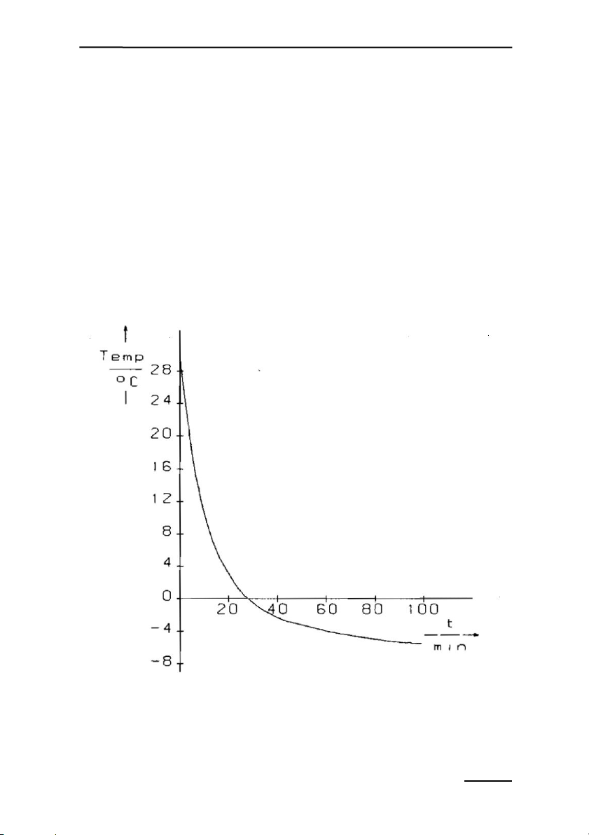
The diagram below (Fig. 6) shows the cooling time for +30 °C down
to -5.5 °C.
Fig. 6: Cooling time for +30 °C down to -5.5 °C for a gas flow of
4 l/min

CHAPTER 4 COLD TRAP KF-18/2B
14
If the measuring gas cooler operates continuously at dew-point tem-
peratures below 0 °C, the conduits may freeze,depending on
the quantity and humidity of the gas. To defrost the unit, switch
off the controller. Alternatively, the dew-point may be set to 10°C
above ambient temperature. The gas flow should be switched off
during defrosting.
Defrosting can be accelerated by removing the Perspex insert from
the interior part. This can be done by loosening the two knurled nuts
at the gas inlet and taking the aluminium plate off. With slight
turning movements the Perspex unit can be withdrawn.
This manual suits for next models
4
Table of contents
Other Heinz Walz Accessories manuals

Popular Accessories manuals by other brands


Grindmaster
Grindmaster PIC-4 Series Parts reference guide

Bison
Bison VB1000 instruction manual

IFM Electronic
IFM Electronic PN50 Series operating instructions

Byron
Byron SX-222 Installation and operation instruction

IMI SENSORS
IMI SENSORS 640B02 Installation and operating manual

ADEMCO
ADEMCO 2700ECM Installation and maintenance instructions