Heinz Walz US-SQS User manual

US-SQS
Spherical Micro Quantum
Sensor
Instruction Manual
3rd Edition: 12-May-11
US-SQS_Manual_3.doc
©Heinz Walz GmbH, 2011
Heinz Walz GmbH •Eichenring 6 •91090 Effeltrich •Germany
Phone +49-(0)9133/7765-0 •Fax +49-(0)9133/5395
Printed in Germany


CONTENT
1Safety Instructions........................................................................1
1.1 General Safety Instructions.......................................................1
2Introduction..................................................................................2
3Sensor Characterization ..............................................................3
3.1 Spectral Response .....................................................................3
3.2 Angular Response .....................................................................4
3.3 Immersion Effect.......................................................................4
4Calibration....................................................................................6
4.1 Calibration Procedure................................................................6
4.2 Calibration Certificate...............................................................6
5Making Measurements ..............................................................10
5.1 General Information................................................................10
5.2 PAM Applications...................................................................10
5.2.1 US-SQS/L.........................................................................10
5.2.2 US-SQS/IB........................................................................10
5.2.3 US-SQS/WB.....................................................................11
5.2.4 US-SQS/B.........................................................................12
5.2.4.1 Exchanging Battery.........................................................12
5.2.5 Black Hood for Suspension Cuvettes................................12
6Cleaning Information.................................................................13
7Terminology................................................................................14
8Literature....................................................................................16
9Technical data.............................................................................17
10 Warranty conditions..................................................................19
I


CHAPTER 1
1
SAFETY INSTRUCTIONS
1Safety Instructions
1.1 General Safety Instructions
1. Read the safety instructions and the operating instructions before
using the instrument.
2. Pay attention to all the safety warnings.
3. Keep electronic parts of the device away from water or high
moisture areas.
4. Keep the device away from dust, sand and dirt.
5. Always ensure there is sufficient ventilation.
6. Do not put the device anywhere near sources of heat.
7. Connect the device only to the power source indicated in the
operating instructions or on the device.
8. Clean the device only according to the manufacturer’s recom-
mendations.
9. Ensure that no liquids or other foreign bodies can find their way
inside the device.
10. The device should only be repaired by qualified personnel.

CHAPTER 2 INTRODUCTION
2
2Introduction
The Spherical Micro Quantum Sensor US-SQS is designed to
measure photosynthetically active radiation (PAR) in suspension cu-
vettes, and specifically the photosynthetic photon fluence rate (PPFR,
see chapter 7). The sensor consists of a 3.7 mm Ø highly scattering
plastic sphere, which detects light from all directions. It is connected
to a 2 mm Ø plastic fiber, which guides the light to a blue enhanced
silicon photodiode equipped with a special filter set for the selection
of photosynthetically active radiation between 380 nm and 710 nm.
The US-SQS/L basic sensor comes with a 3 m coaxial cable and a
BNC connector. It is connectable to any data logger with micro-
Ampere current measuring function. WALZ offers the ULM-500
(Universal Light Meter 500) for data acquisition.
In conjunction with various mechanical and electrical accessories
the US-SQS is suitable for different applications and instruments.

CHAPTER 3 SENSOR CHARACTERIZATION
3
3Sensor Characterization
3.1 Spectral Response
Figure 1a shows the typical response between 350 nm and
1100 nm of an US-SQS sensor. The solid line shows the ideal re-
sponse of a photon fluence sensor for photosynthetically active radia-
tion (PAR, defined for the 400-700 nm wavelength range; for defini-
tions see chapter 7). For comparison Figure 1b, shows the absolute
response to energy fluence rate from 350-750 nm.
Fig. 1a: Absolute spectral sensitivity for Photon Fluence Rate
Fig. 1b: Absolute spectral sensitivity for Energy Fluence Rate
Absolute Spectral Sensitivity S(λ) for Photon Fluence Rate
(current per photon events)
0.0
0.5
1.0
1.5
2.0
2.5
3.0
3.5
4.0
4.5
350 400 450 500 550 600 650 700 750 800 850 900 950 1000 1050 1100
Wavelength (nm)
µA per mmol m
-2
s
-1
SQSA0246
Norm
Absolute Spectral Sensitivity S(λ) for Energy Fluence Rate
0.000
0.005
0.010
0.015
0.020
0.025
350 400 450 500 550 600 650 700 750
Wavelength(nm)
µA per W m
-2
SQSA0246
Norm

CHAPTER 3 SENSOR CHARACTERIZATION
4
3.2 Angular Response
The US-SQS sensor uses a plastic diffuser to obtain an angular re-
sponse error of less than ± 5 % (-100°..100° angle).
Figure 2 shows a typical angular response curve.
Fig. 2: Angular response
3.3 Immersion Effect
Because of the different refraction indices of air and water, the
calibration constant of the US-SQS in water differs from that in air.
This phenomenon is known as the immersion effect. The air/water
ratio of the calibration constant is equal to the sensor output in air
divided by the sensor output in water for the same radiation.
The immersion effect correction factor was determined experi-
mentally according to Roemer and Hoagland (1976).
Angular Response US-SQS/L
50
60
70
80
90
100
110
-180 -150 -120 -90 -60 -30 0 30 60 90 120 150 180
deg
%
CHAPTER 3
5
SENSOR CHARACTERIZATION
A collimated beam was directed perpendicularly upon the sensor.
The response of the sensor was recorded in air and in distilled water at
discrete water depths.
The response in water relative to the response in air in dependence
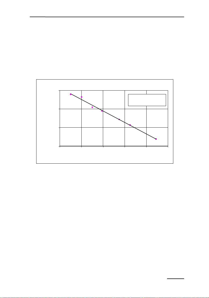
of depth was fitted with a least squares regression line and extrapo-
lated to a depth of 0 mm (see Fig. 3).
immersions
y = -0.0003x + 0.5613
R2= 0.9932
0.53
0.54
0.55
0.56
0 204060801
water depth (mm)
response in water relative to
response in air
00
Fig. 3: Determination of immersion factor
The obtained relative response for zero depth was corrected for
2% radiation loss at the air-water interface. The reciprocal of the ob-
tained value results in the immersion correction factor given in the
calibration certificate. For example for the regression line shown in
Fig. 3 the immersion correction factor is 1.75.
For more information on the dependence of the immersion factor
on the refraction index see Austin (1976) and the refraction index of
the sea water, see Austin and Halikas (1976).
The immersion factor in the calibration certificate is given for dis-
tilled water.

CHAPTER 4 CALIBRATION
6
4Calibration
4.1 Calibration Procedure
US-SQS sensors are calibrated using a LI-COR working standard
calibration lamp. The LI-COR standard lamp has been calibrated
against a reference standard lamp traceable to the National Institute of
Standards and Technology USA (NIST). The lamp is a 200 W tung-
sten halogen lamp operated at a color temperature of 3150° Kelvin.
The lamp is mounted in a LI-COR optical radiation calibrator Model
1800-02. Calibration accuracy of the optical radiation calibrator is ± 4
% from 350-1000 nm.
Spectral sensitivity is calibrated using a Bentham TMc300F
Monochromator system and a reference diode. The reference diode is
calibrated against a standard diode traceable to the NIST. Accuracy
from 380 - 900 nm is ± 5 %.
The calibration constant given in the calibration sheet, takes into
account the spectral difference between the calibration lamp and natu-
ral sun light. The spectrum used for natural sun light is ASTM G-173-
03-global tilt (ISO 9845-1, 1992). As a result the reading for the
PPFR value is most accurate in natural sun light.
4.2 Calibration Certificate
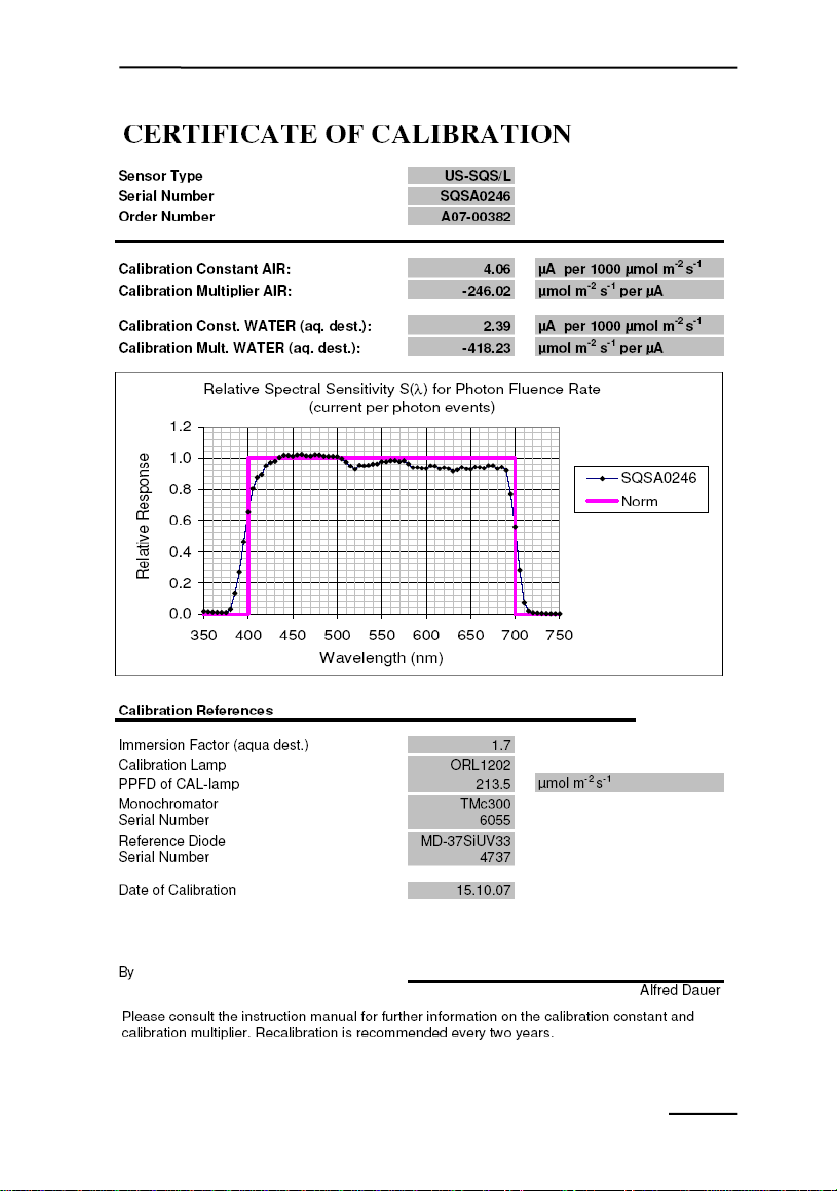
Every US-SQS is accompanied by a certificate. Figure 4 shows a
typical certificate of calibration.
The Calibration Multiplier given in the certificate is the value that
needs to be entered into the ULM-500 for the direct reading of PPFR
values in calibrated units: µmol m-2 s-1.
There are two Calibration Multipliers given, one for the usage in
air, the other for the usage in water.
CHAPTER 4 CALIBRATION
7
Fig. 4a: First page of a typical calibration certificate
CHAPTER 4 CALIBRATION
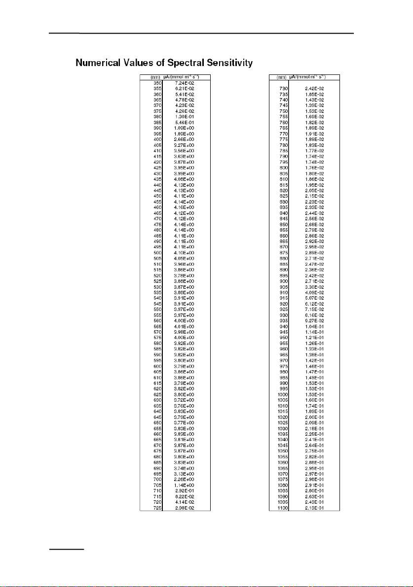
8
Fig. 4b: Second page of a typical calibration certificate

CHAPTER 4
9
CALIBRATION
For a particular light source with known spectrum, the accuracy of
the reading can be increased by using the supplied information for the
relative sensitivity (S(λ)).
For example for an LED light with a narrow spectrum peaking at
640 nm the correction can be done as follows: If the reading is 1000
µmol m-2 s-1 divide the reading by 0.93 (see graph in Fig. 4a) resulting
in 1073 µmol m-2 s-1.
CHAPTER 5 MAKING MEASUREMENTS
10
5Making Measurements
5.1 General Information
Before you start the measurement, connect the sensor to your dis-
play or data-logging device and remove the clear acrylic protection
shield. Make sure the calibration factor is entered correctly in the data
logger, when using the US-SQS/L or US-SQS/IB (see below). The
US-SQS/WB and the US-SQS/B come with an amplifier. The sensor
specific calibration factor is set within this amplifier during manufac-
turing and can not be changed by the user (see below).
5.2 PAM Applications
The basic sensor US-SQS/L can be combined with special ampli-
fiers for different PAM instruments. For PAM applications with sus-
pension cuvettes, we provide a version with an adjustable black hood.
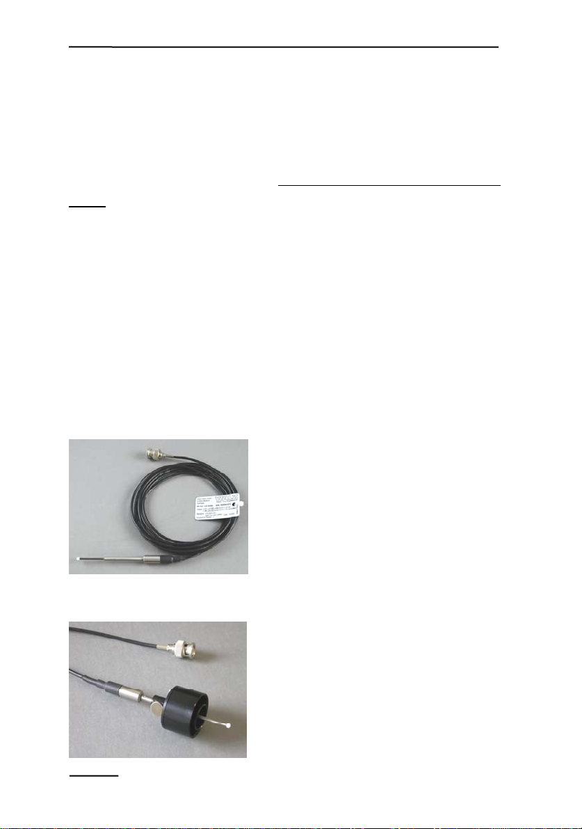
5.2.1 US-SQS/L The US-SQS/L consists of the
sensor with a 3 m cable and BNC con-
nector. It can be connected to the
ULM-500 or other data loggers.
5.2.2 US-SQS/IB The US-SQS/IB has an adjustable
black hood. The ULM-500 or another
external data logger is required. The
US-SQS/IB is recommended for the
use with a PAM-100 or XE-PAM.
CHAPTER 5 MAKING MEASUREMENTS
11
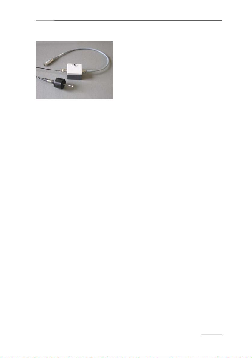
5.2.3 US-SQS/WB The US-SQS/WB has a hood and
an amplifier box. With this amplifier
box the light sensor can be connected
to several PAM instruments.
Technically the connection for the US-
SQS/WB is the same as for the leaf-
clip holder 2030-B. In particular the
possible connections are:
PAM Control Unit of WATER-PAM (Aux Input),
PDA-100 of PAM-100 or XE-PAM (Aux Input),
Dual-PAM-100 (AUX),
ULM-500 (AUX)
but also:
PAM-2100 (Leaf Clip),
Mini-PAM (Leaf Clip)
The amplifier of the US-SQS/WB is adjusted to the particular
calibration factor of the sensor for the use in water. Therefore the
displayed values are only correct, if the sensor is submersed in water.
This is always the case, no matter whether the sensor is connected to a
PAM-Control Unit or Mini-PAM.
The displayed value is 0 to 20 000 µmol m-2 s-1 PAR, if the switch
is set to x1. The setting x10 amplifies the signal and displayed value
ten-fold and can only be used for low light intensities (0...100 µmol
m-2 s-1). Above 100 µmol m-2 s-1 the setting x10 leads to erratic data
readings.

CHAPTER 5 MAKING MEASUREMENTS
12
5.2.4 US-SQS/B The US-SQS/B has a hood and an
amplifier box, which contains a
battery.
It can be connected to the
Phytoplankton Analyzer PHYTO-
PAM. The US-SQS/B connects to the
AUX-INPUT port on the front side of the Power-and-Control-Unit.
The amplifier of the US-SQS/B is adjusted to the particular cali-
bration factor of the sensor for the use in water. Displayed values are
only correct, if the sensor is submersed in water.
5.2.4.1 Exchanging Battery
For exchanging the
battery, unscrew all four
screws at the top of the
amplifier-housing. Take
out the battery. Exchange
it and put everything
back together.
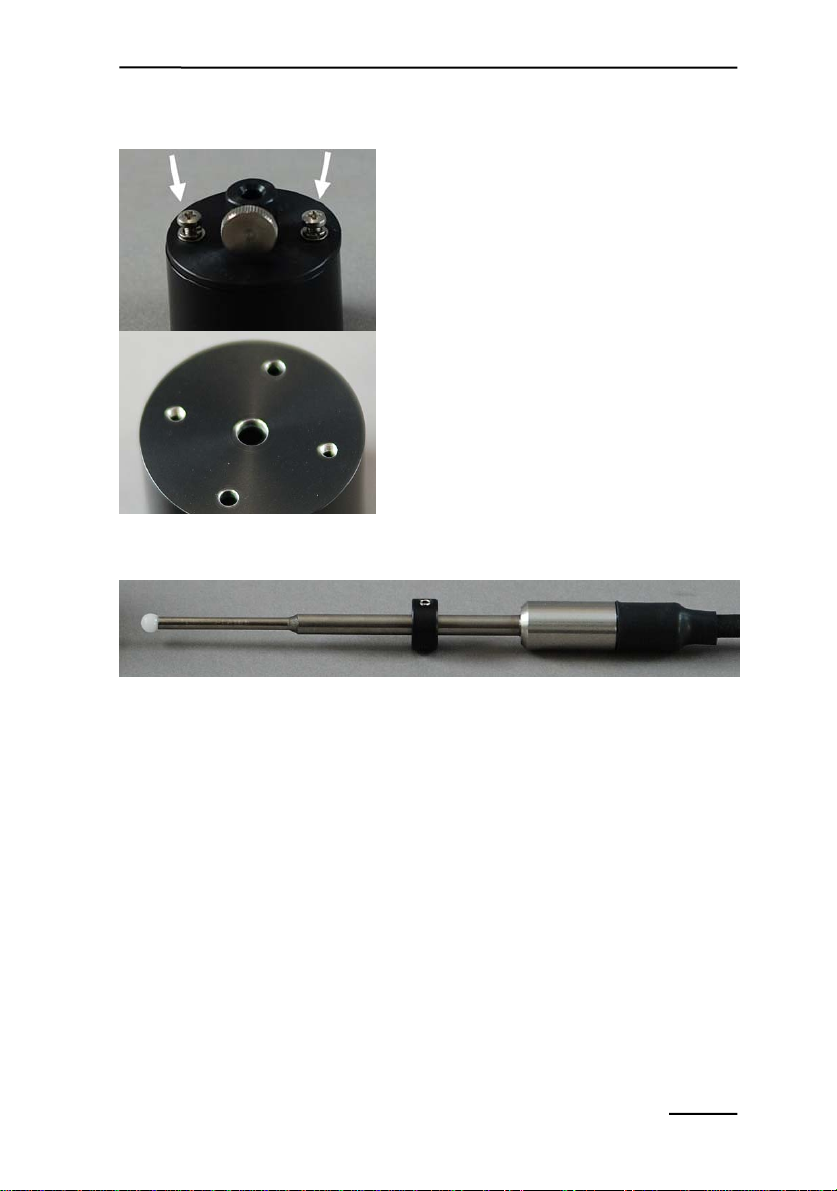
5.2.5 Black Hood for Suspension Cuvettes
The adjustable black hood for sus-
pension cuvettes has two configura-
tions: with or without inner ring. With
inner ring, it fits the Emitter-Detector
Unit PHYTO-ED for round cuvettes.
Without inner ring, it fits the Optical Unit for Suspensions ED-
101US/MD for squared cuvettes.
CHAPTER 5
13
MAKING MEASUREMENTS
To remove the inner ring, unscrew
the indicated screws. Afterwards use
the screws to fix the upper plate to the
threaded holes of the hood.
The threaded holes of the hood are
in a 90° position to the unthreaded
holes.
The hood is provided with a small
positioning help, which can be left on
the shaft of the sensor, when the hood is removed.
6Cleaning Information
Do not use organic solvent, abrasives or strong detergents to clean
the diffuser. Clean the sensor only with water and/or a mild detergent
such as dish washing soap or mild diluted window cleaner. Never use
acetone.

CHAPTER 7 TERMINOLOGY
14
7Terminology
PAR: Photosynthetically Active Radiation
Photosynthetically active radiation is usually defined as radiation
between 400 and 700 nm. Radiation can be used energy based (W) or
photon event based (µmol/s). In photosynthesis most effects are de-
pendent on the amount of photons rather than the energy incident on
the system. Therefore, we characterize the sensors in photon event
based units (µmol/s).
Sometimes PAR has been used weighted according to the plant’s
photosynthetic response similar to the unit lux, which is weighted
according to the standard human eye’s sensitivity. We do not use
PAR weighted, (see norm-curve in Fig. 1), because PAR is expressed
in SI-units, which is not weighted per definition. Furthermore, correct
weighting would depend on the pigmentation of the organism, which
varies between different plants and between different types of phyto-
plankton in particular.
Photon Flux
Number of photons per time interval (Braslavsky, 2007). Unit: s-1
or µmol s-1
Photon Irradiance
Number of photons per time interval incident from all upward di-
rections on a small element of surface containing the point of consid-
eration divided by the area of the element (Braslavsky, 2007). The
term “all upward directions” expresses the fact that the receiver is not
a sphere but a flat surface and only beams from one hemisphere take
effect, of which beams not perpendicular to the surface only contrib-
ute with the cosine of the angle between the beam and the surface
normal. Unit: µmol m-2 s-1.

CHAPTER 7
15
TERMINOLOGY
PPFD: Photosynthetic Photon Flux Density.
The term photon flux density is often used equivalent to photon ir-
radiance (see above for exact definition, compare Björn 2008).
The photosynthetic photon flux density is restricted to the range
of wavebands between 400 and 700 nm. Unit: µmol m-2 s-1.
PPFD is measured with cosine corrected sensors having a plane
surface (e.g. the Micro quantum sensor MQS).
PPFR: Photosynthetic Photon Fluence Rate.
The photon fluence rate is defined as total number of photons in-
cident per time interval from all directions on a small sphere divided
by the cross-sectional area of the sphere (Braslavsky, 2007). It has
also been called photon spherical irradiance, scalar irradiance or pho-
ton flux fluence rate.
The photosynthetic photon fluence rate is restricted to the range of
wavebands between 400 and 700 nm. Unit: µmol m-2 s-1
PPFR is measured with spherical sensors.

CHAPTER 8 LITERATURE
16
8Literature
Austin R.W. (1976) Air-water radiance calibration factor. Scripps Insti-
tution of Oceanography, La Jolla, CA. Tech. Memo. ML-76-004T 8 pp.
Austin R.W. and Halikas G. (1976) The index of refraction of seawater.
Scripps Institution of Oceanography, La Jolla, CA. SIO Reference 76-1, 64
pp.
Björn L.O. (2008) Principles and nomenclature for the quantification of
light (chapter 2). In: Photobiology. The Science of Life and Light. Springer-
Verlag, Berlin, Heidelberg, New York, 42-49
Braslavsky S.E. (2007) Glossary of terms used in photochemistry, 3rd
edition (IUPAC Recommendations 2006). Pure and Applied Chemistry 79,
293-465
Roemer S.C. and Hoagland K.D. (1976) Immersion effect and cosine
collecting properties of Li-Cor underwater sensors. School of Life Sciences,
University of Nebraska, Lincoln, Nebraska 11pp.
Table of contents
Other Heinz Walz Accessories manuals

Popular Accessories manuals by other brands


Oras
Oras 198584 Installation and maintenance guide

Snapper
Snapper 1692210, 1692231, 1692353, 9000100 installation instructions

Sensata
Sensata Nanoprecise 6VW Operation manual

PowerTech
PowerTech CUBE 200 POWERBEAM instruction manual

MSA
MSA ICM TxR Unit Operation instructions

WirelessWERX
WirelessWERX SiteWERX user manual