HEKA Elektronik EPC 10 USB User manual

Hardware Manual Version 2.8
EPC 10 USB
Computer-controlled Patch Clamp Amplifier

HEKA Elektronik Phone +49 (0) 6325 95 53-0
Dr. Schulze GmbH Fax +49 (0) 6325 95 53-50
Wiesenstrasse 71 Web Site www.heka.com
D-67466 Lambrecht/Pfalz Email sales@heka.com
Germany support@heka.com
HEKA Electronic Phone +1 800 597 0580
84 October Hill Road Fax +1 508 429 5732
01746 Holliston Web site www.heka.com
Massachusetts Email sales@heka.com
United States support@heka.com
©
2007-2018 HEKA Elektronik Dr. Schulze GmbH
COMDE1/9

Contents
1 Introduction 1
1.1 IntroducingtheEPC10USB ........................................ 1
1.2 References................................................... 2
1.3 NamingConventions............................................. 3
2 Description of the Hardware 5
2.1 Headstage................................................... 5
2.2 RedStarHeadstage ............................................. 5
2.3 MainUnit................................................... 6
2.3.1 Front-panel .............................................. 6
2.3.2 Rear-panel .............................................. 8
2.4 EPC 10 USB DOUBLE, TRIPLE, and QUADRO . . . . . . . . . . . . . . . . . . . . . . . . . . . . 8
2.5 Special Features of the EPC 10 USB . . . . . . . . . . . . . . . . . . . . . . . . . . . . . . . . . . . . 9
2.5.1 Timing of the AD-/DA-channels . . . . . . . . . . . . . . . . . . . . . . . . . . . . . . . . . . 9
3 Installation 11
3.1 InstallingSoftwareonly ........................................... 11
3.2 Installing Hardware and Software . . . . . . . . . . . . . . . . . . . . . . . . . . . . . . . . . . . . . . 11
3.3 Conventions.................................................. 11
3.4 ConnectingtheHardware .......................................... 12
3.5 Protection Key (’Dongle’) Installation . . . . . . . . . . . . . . . . . . . . . . . . . . . . . . . . . . . 12
3.5.1 USBDongleInstallation....................................... 12
3.5.1.1 MSWindows........................................ 13
3.5.1.2 MacOS ........................................... 13
3.6 SoftwareInstallation............................................. 13
3.6.1 MSWindows ............................................. 13
3.6.2 MacOS ................................................ 13
3.7 CalibratingtheHardware .......................................... 14
3.8 SupportHotline................................................ 15
4 Verifying and Testing the EPC 10 USB 17
4.1 Testing the EPC 10 USB with the Model Circuit . . . . . . . . . . . . . . . . . . . . . . . . . . . . . 17
4.1.1 TheModelCircuit .......................................... 17
4.1.2 ”SETUP” - Applying the Test Pulse . . . . . . . . . . . . . . . . . . . . . . . . . . . . . . . . 17
4.1.3 ”SEAL” - Voltage Clamp Recording . . . . . . . . . . . . . . . . . . . . . . . . . . . . . . . . 19
4.1.4 ”Whole-Cell” - Voltage Clamp Recording . . . . . . . . . . . . . . . . . . . . . . . . . . . . . 21

ii CONTENTS
4.1.5 ”Whole-Cell” - Current Clamp Recording . . . . . . . . . . . . . . . . . . . . . . . . . . . . . 23
4.1.6 Measuring the Noise of the Amplifier . . . . . . . . . . . . . . . . . . . . . . . . . . . . . . . . 24
4.2 MakingaFullTest.............................................. 25
5 The control software 27
5.1 EPC10USBWindow ............................................ 27
5.1.1 MainControls ............................................ 27
5.1.2 HiddenControls ........................................... 34
5.2 EPC10USBMenu.............................................. 37
5.2.1 TestandCalibrateMenu ...................................... 37
6 Operating Modes 39
6.1 VoltageClampMode............................................. 39
6.2 CurrentClampMode ............................................ 39
6.3 Low Frequency Voltage Clamp Mode . . . . . . . . . . . . . . . . . . . . . . . . . . . . . . . . . . . . 40
6.4 SearchMode ................................................. 40
7 Compensation Procedures 43
7.1 SeriesResistanceCompensation....................................... 43
7.2 CapacitanceCompensation ......................................... 45
7.3 OffsetCompensation............................................. 46
8 Patch Clamp Setup 49
8.1 MountingtheProbe ............................................. 49
8.2 GroundWires................................................. 49
8.3 GroundingtheMicroscope.......................................... 49
8.4 ExternalShielding .............................................. 49
8.5 Connections to other Instruments . . . . . . . . . . . . . . . . . . . . . . . . . . . . . . . . . . . . . . 50
8.6 PipetteHolderandElectrode ........................................ 50
8.7 BathElectrode ................................................ 50
9 Patch Pipettes 53
9.1 GlassCapillaries ............................................... 53
9.2 Pulling..................................................... 53
9.3 Coating .................................................... 54
9.4 HeatPolishing ................................................ 54
9.5 UseofPipettes ................................................ 54
10 Using the Patch Clamp 55
10.1FormingaSeal ................................................ 55
10.1.1 InitialSetup ............................................. 55
10.1.2 EnteringtheBath .......................................... 55
http://www.heka.com

CONTENTS iii
10.1.3 FormingaGigaseal.......................................... 55
10.2Cell-AttachedRecording........................................... 55
10.3Whole-CellRecording ............................................ 56
10.3.1 BreakingthePatch.......................................... 56
10.3.2 Capacitive Transient Cancellation . . . . . . . . . . . . . . . . . . . . . . . . . . . . . . . . . 56
10.3.3 Series Resistance Compensation . . . . . . . . . . . . . . . . . . . . . . . . . . . . . . . . . . 57
10.4CurrentClampRecording .......................................... 57
11 Low Noise Recording 59
12 Appendix I: Digital Inputs/Outputs 61
12.1DigitalI/OConnector ............................................ 61
12.2DigitalInConnector............................................. 62
12.3DigitalOutConnector............................................ 62
12.4BreakoutCable................................................ 63
12.5ConnectingCables .............................................. 63
12.5.1 DG 4/5 / Lambda 10-2 / Lambda 10-3 to EPC 10 USB . . . . . . . . . . . . . . . . . . . . . 63
12.5.2 ValveLink8toEPC10USB .................................... 65
13 Appendix II: Probe Adapters 67
13.1StandardMountingPlate .......................................... 67
13.2DovetailMountingPlate........................................... 67
14 Appendix III: S-Probe 69
15 Appendix IV: Pipette Holder 71
15.1BNC-Type .................................................. 71
15.2SMA-Type .................................................. 71
http://www.heka.com

1. Introduction
The patch clamp technique was introduced by Neher and Sakmann (1976) for recording the currents in a small patch
of membrane under voltage clamp conditions. In the intervening years a number of changes have occurred, most
notably the development of the ”gigaseal” by E. Neher (1981). Various recording configurations allow intracellular
recordings to be made with the same type of recording setup as used for patch recording from the cell surface or
cell-free membrane patches (Hamill et al., 1981).
1.1 Introducing the EPC 10 USB
Figure 1.1: EPC 10 USB Patch Clamp amplifier
The EPC 10 USB represents roughly the tenth in the series of patch clamp designs in use in the G¨ottingen
laboratories. It is a logical successor to the classical EPC 7, retaining all of its features but adding a number of
capabilities. Like the EPC 9, the EPC 10 USB implements full digital control of the various functions. Thus,
the digitally controlled EPC 10 USB patch clamp amplifier has no knobs, switches or dials. The acquisition
software (Patchmaster) replaces the analog controls of conventional amplifiers by using a computer and a built-
in AD/DA converter. The convenient graphics display and mouse operations provide unsurpassed versatility and
ease of operation. In addition to the controls for the amplifier and the built-in filters, our acquisition software
contains a powerful data acquisition system (sampling and storage in pulse, ramp and continuous modes), a fully
programmable Pulse Generator, a digital Oscilloscope and the Protocol Editor for automation processes. Thus, the
EPC 10 USB offers all the features of a complete workstation for controlling experiments and acquiring data.
Furthermore, there are several analysis software packages available, which allow data analysis, data export, and
graphics output.
The EPC 10 USB also accepts a stimulus input and provides analogue current and voltage monitor outputs
just like conventional amplifiers to operate in combination with a host computer running custom and commercial

2 Introduction
software from other sources. The versatility of the EPC 10 USB can best be appreciated by the variety of
experiments that can be carried out with it. Besides high-resolution recordings of single channels, it can be
used in studies of whole-cell voltage and current clamp, exocytosis (by monitoring changes in cell membrane
capacitance), and recordings from artificial membranes or loose-patch experiments. Technically, the EPC 10 USB
is noteworthy for three special features, the range-changing capability of the probe, the extremely wide bandwidth
available from the current monitor circuitry, and the integrated transient cancellation (automatically if desired)
and series-resistance compensation functions. In current clamp mode, the EPC 10 USB pre-amplifier acts as an
“voltage-follower”, similar to classical microelectrode amplifiers, which guarantees very fast and accurate membrane
potential recordings (Magistretti et al., 1996). Together, these features mean that a single probe suffices for both
single-channel and whole cell recordings, and that both kinds of recordings can be made with high time resolution
and low noise.
This manual is designed to provide a general guide for setting up and using the EPC 10 USB for experiments.
It covers general information about the hardware, basic principles of the EPC 10 USB’s functions and patch
clamp techniques. It is assumed that the reader has some familiarity with patch clamp techniques; should you be a
newcomer to the field perhaps the best place to start would be the paper by Hamill et al., where the basic gigaseal
techniques are described and the first three chapters of Single Channel Recording (B. Sakmann & E. Neher, eds.,
Plenum Press, New York, 1995). Certainly, it will be worthwhile to read this manual carefully. Many users will
want to read some of the more advanced and complete discussions of individual topics which can be found in
original articles and in the books Single Channel Recording (B. Sakmann & E. Neher, eds., Plenum Press, New
York, 1995) and Methods in Enzymology, vol. 207 (Academic Press, New York, 1992).
1.2 References
Original Articles
Hamill, O. P., Marty, A., Neher, E., Sakmann, B. & Sigworth, F. J. (1981) Improved patch clamp techniques for
high-resolution current recording from cells and cell-free membrane patches. Pflugers Arch. 391, 85-100.
Magistretti, J., Mantegazza, M., Guatteo, E. & Wanke, E. (1996) Action potentials recorded with patch-clamp
amplifiers: are they genuine? TINS 19, 530-534.
Neher, E. (1981) Unit conductance studies in biological membranes. In: Techniques in Cellular Physiology (P. F.
Baker, ed.) Elsevier/North Holland.
Neher, E. & Sakmann, B. (1976) Single-channel currents recorded from membrane of denervated frog muscle fibres.
Nature 260, 779-802.
Rae, J. & Levis, R. (1984) Patch clamp recordings from the epithelium of the lens obtained using glasses selected
for low noise and improved sealing properties. Biophys. J. 45, 144-146.
Barry, P. H. & Lynch, J. W. (1991) Liquid junction potentials and small cell effects in patch-clamp analysis. J.
Memb. Biol. 121, 101-117.
Sigworth, F. J., Affolter, H. & Neher, E. (1995) Design of the EPC-9, a computer-controlled patch-clamp amplifier.
2. Software. J. Neurosci. Methods 56, 203-221.
Peters, F., Gennerich, A., Czesnik, D. & Schild, D. (2000) Low frequency voltage clamp: recording of voltage
transients at constant average command voltage. J. Neuroscience Meth. 99, 129-135.
Gillis, K.D. (2000) Admittance-based measurements of membrane capacitance using the EPC-9 patch-clamp am-
plifier. Pflugers Arch. 439:655-664.
Book Chapters
Penner, R. (1995) Chapter 1: A practical guide to patch clamping. In: Single-Channel Recording (B. Sakmann &
E. Neher, eds.) Plenum Press, New York.
Marty, A. & Neher, E. (1995) Chapter 2: Tight-seal whole-cell recording. In: Single-Channel Recording (B.
Sakmann & E. Neher, eds.) Plenum Press, New York.
Heinemann, S. H. (1995) Chapter 3: Guide to data acquisition and analysis. In: Single-Channel Recording (B.
http://www.heka.com

1.3 Naming Conventions 3
Sakmann & E. Neher, eds.) Plenum Press, New York.
Sigworth, F. J. (1995) Chapter 4: Electronic design of the patch clamp. In: Single Channel-Recording (B. Sakmann
& E. Neher, eds.) Plenum Press, New York.
Neher, E. (1995) Chapter 6: Voltage offsets in patch-clamp experiments. In: Single Channel-Recording (B. Sak-
mann & E. Neher, eds.) Plenum Press, New York.
Colquhoun, D. & Sigworth, F. J. (1995) Chapter 19: Fitting and statistical analysis of single-channel records. In:
Single-Channel Recording (B. Sakmann & E. Neher, eds.) Plenum Press, New York.
Neher, E. (1992) Correction for liquid junction potentials in patch clamp experiments. In: Methods in Enzymology
207, 123-131, Academic Press, New York.
1.3 Naming Conventions
EPC 10 USB Single, EPC 10 USB Double, EPC 10 USB Triple and EPC 10 USB Quadro: Throughout
the present manual we will address all EPC 10 USB amplifier types as “EPC 10 USB”. We will explicitly mention
the particular amplifiers, where it is required.
MS Windows versions
The EPC 10 USB is supported by Windows XP, Windows 7, Windows 8 and Windows 10.
Throughout the present manual we will address all the above Windows versions as “MS Windows”. We will
explicitly mention the particular MS Windows versions, whenever it is required. A free USB 2.0 port is required.
Macintosh
The EPC 10 USB USB is supported by Macintosh computers running Mac OS X 10.4 or newer. A free USB 2.0
port is required.
http://www.heka.com

4 Introduction
http://www.heka.com
2. Description of the Hardware
The hardware components of the EPC 10 USB series patch clamp system consist of the headstage (or probe), the
amplifier main unit with an integrated AD/DA converter board. The EPC 10 USB amplifier is connected to the
computer via a USB 2.0 cable. Specific information about the hardware installation is given below in chapter 3 on
page 11.
2.1 Headstage
The EPC 10 USB can be used with different headstages. The default headstage delivered with the EPC 10 USB
is the Red Star headstage. Other exchangable headstages are available:
S-Probe (see chapter 14 on page 69)
3 Electrode Headstage
Amperometry Headstage
If you are interested in another headstage and their appropriate purpose please contact us (sales@heka.com).
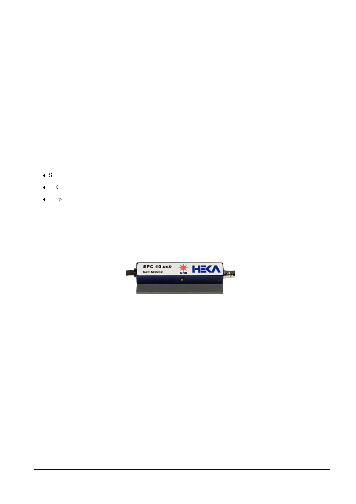
2.2 Red Star Headstage
Figure 2.1: EPC 10 USB Red Star Headstage
The probe of the EPC 10 USB is contained in a small enclosure, designed to be mounted on a micromanipulator
and directly attached to the recording micropipette. It contains the sensitive amplifier that constitutes the current-
to-voltage converter, as well as components for injecting signals into that amplifier. On the probe are the following
connectors:
Input Connector: This is a Teflon-insulated BNC connector. The standard pipette holder plugs directly into
this connector; the center pin is the amplifier input, and the shield is driven with the command potential (Vp).
Important note: Avoid touching the probe’s input terminal, since the input circuitry of the probe can
be damaged by static electricity. When it is necessary to touch the input (e.g., while inserting a pipette
into the holder), ground yourself first by touching a grounded metal surface.
GND Connector: The black pin jack carries a high quality ground signal which is useful for grounding the bath
electrode and nearby shields without potential errors that could arise from ground loops. This ground is connected
directly to the signal ground on the controller through the probe’s cable. More details on grounding practices will
be provided in chapter 8 on page 49.
6 Description of the Hardware
2.3 Main Unit
The main unit of the EPC 10 USB contains the power supply, the signal processing electronics, the A/D and D/A
converters and the connectors for analog and digital input/output. Essentially all of the calibration adjustments
are made by digital switches in the main unit, including those which depend on the properties of components in
the probe. The calibration parameters are preset by the manufacturer and contained in the software package as
the files ”Scale-xxxxxx.epc” and ”Cfast-xxxxxx.epc”. Unlike conventional amplifiers, hardware calibration of
the EPC 10 USB can also be performed by the user if necessary (see chapter 3.7 on page 14).
Note: Calibration parameters are unique to each amplifier and probe combination. Thus, if you ex-
change the probe, be sure to perform a new hardware calibration.
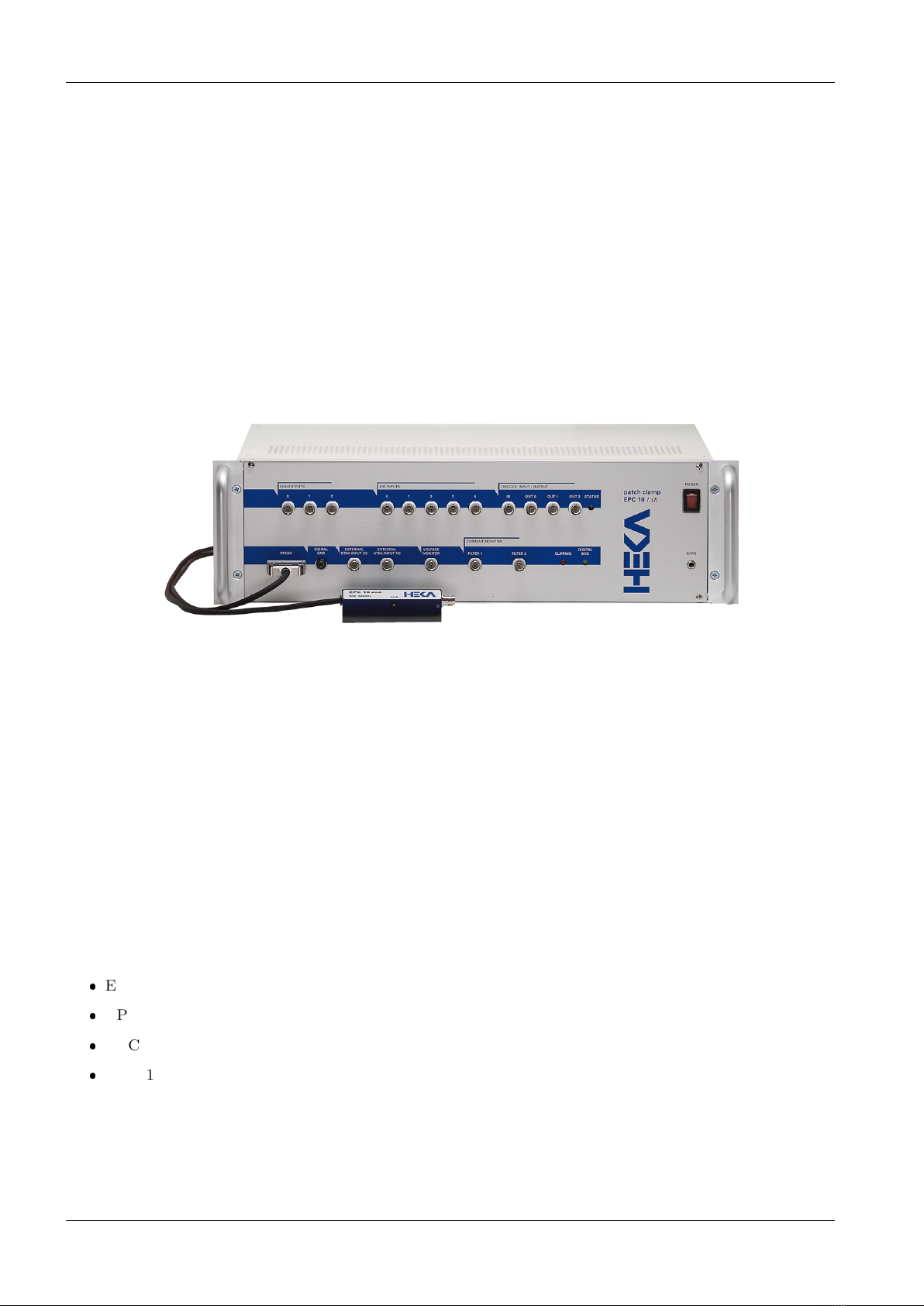
2.3.1 Front-panel
Figure 2.2: EPC 10 USB Front Panel
Power Switch: In order to be initialized properly, the EPC 10 USB must be switched on before starting
the software program that drives it, e.g., Patchmaster. These programs however allow you to re-initialize the
amplifier in case you forgot to turn it on first.
Note: Since the calibration settings of the amplifier have been determined for a warmed-up amplifier,
switch on the amplifier ∼30 min before starting an experiment. This will ensure that the amplifier has
warmed up to regular working temperature and calibration parameters are most accurate.
CHAS (Chassis Ground): The chassis is connected to the ground line of the power cord, as is typical of most
instruments. The Signal Ground (Signal GND) is kept separate from the chassis to avoid ground loops, but is
connected to it through a 10 Ω resistor.
D/A Outputs: The built-in interface (LIH 8+8) provides four D/A output channels (DA-0 - DA-3). Regarding
the different versions of the EPC 10 USB the following D/A output channels are freely available:
EPC 10 USB USB Single: DA-0, DA-1, DA-2
EPC 10 USB USB Double: DA-0, DA-1
EPC 10 USB USB Triple: DA-0
EPC 10 USB USB Quadro: none
Important note: These are output connectors! Make sure that you never feed stimuli into these
outputs.
A/D Inputs: The built-in interface (LIH 8+8) provides eight A/D input channels (AD-0 - AD-7). Regarding
the different versions of the EPC 10 USB the following A/D output channels are freely available:
http://www.heka.com

2.3 Main Unit 7
EPC 10 USB USB Single: AD-0, AD-1, AD-2, AD-3, AD-4
EPC 10 USB USB Double: AD-0, AD-1, AD-2
EPC 10 USB USB Triple: AD-0
EPC 10 USB USB Quadro: none
For example, the Patchmaster program can use these channels to monitor temperature, pressure or outputs from
other sensors.
Trigger Input: Input for an external trigger to start data acquisition when the amplifier is waiting for an external
trigger. This mode is set in Patchmaster when either Trigger Series or Trigger Sweeps is selected in the Pulse
Generator ofPatchmaster.
Trigger Output: Three TTL trigger outputs for synchronization of your patch clamp experiments with other
devices.
Probe: This input accepts the multi-pin connector of the probe.
Signal GND: This banana jack is a high-quality signal ground connection that can be used to ground other parts
of the experimental setup as necessary (see chapter 8 on page 49).
External Stim. Input CC: Signals from an external stimulus source are applied here; they can be summed with
the internal stimulus if desired.
External Stim. Input VC: Signals from an external stimulus source are applied here. They can be summed
with the internal stimulus if desired. The combined stimulus signal is passed through a 2-pole filter to round off
stepwise changes in voltage. This avoids nonlinearities (from slew-limiting amplifiers) in the command processing
circuitry and also reduces the amplitude of the current transients from rapid charging of the pipette. Two degrees
of filtering, specified as the rise times (time from 10% to 90% of the amplitude of a step change) are available in the
software: 2 µs, which is the minimum required to avoid nonlinearities in the internal circuitry, and 20 µs, which is
preferable for all but the fastest measurements, to reduce the capacitive transients.
Voltage Monitor: This output signal provides a monitor of the pipette potential. It is scaled up by a factor of
10 relative to the potential applied to the pipette. The output impedance is 50 Ω. The unscaled signal may be
viewed on the software oscilloscope.
Current Monitor: The output signals are filtered according to the settings in the software. Positive voltages
correspond to currents flowing out of the pipette. Typically, the Filter 1 is fed to a data recorder (e.g., tape
recorder, PCM/VCR combination, DAT recorder, amplification unit) to record the signal at wide bandwidth,
while the additionally-filtered signal from Filter 2 is applied to an oscilloscope for monitoring the progress of the
experiment. Either signal may be viewed on the software Oscilloscope window.
Clipping: This LED lights whenever an amplifier saturates in the current monitor pathway. The indicator is
important in voltage clamp experiments where capacitive artifacts will be subtracted in the host computer; the
subtraction will work well only as long as no saturation occurs, and this indicator serves as a simple monitor of this
condition. It is particularly useful since it will indicate clipping by internal amplifiers even in cases where, because
of filtering, the output voltage is not saturated.
Digital Bus: This LED lights whenever digital information is sent from the computer to the EPC 10 USB
amplifier.
Note: Prior to the initialization of the amplifier the status of the Clipping and the Digital Bus LEDs
is irrelevant.
http://www.heka.com
8 Description of the Hardware
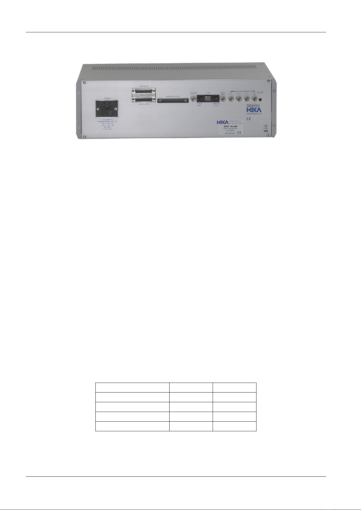
2.3.2 Rear-panel
Figure 2.3: EPC 10 USB Rear Panel
Power: Connect the enclosed power cord to this connector. It is not necessary to switch between different voltage
ranges manually. The built-in power supply detects and covers the two major voltage ranges of 90-120 V and
210-250 V at 50-60 Hz.
Digital Out / Digital In: TTL-level, digital input and output lines are available here for the control and
monitoring of digital signals (see chapter 12.2 on page 62).
Digital I/O: This connector can be used to connect an EPC 8 patch clamp amplifier or a TIB 14 trigger interface
box to the EPC 10 USB amplifier.
Trigger: This port does not exist any more. Use Trigger In on the front panel of the EPC 10 USB.
USB: This port is the connection to the USB 2.0 port in the host computer, that allows the computer to commu-
nicate with the EPC 10 USB.
Slave Sync / Master Sync: 2 CAT5 connectors for synchronization of a second amplifier (EPC 10 USB only)
or interface (LIH 8+8 only) system.
AUX DAC / Telegraphing Inputs: These ports are for inspection purposes only.
Sound: A 3.5 mm jack for connecting phones or speakers. The volume and resistance/frequency ration can be
adjusted by the Patchmaster software.
2.4 EPC 10 USB DOUBLE, TRIPLE, and QUADRO
The EPC 10 USB Double, Triple, and Quadro contain two, three and four independent EPC 10 USB amplifiers
in one case, respectively. All amplifiers share a single AD/DA board. The AD/DA board provides 4 DA channels
which are sufficient to allow simultaneous stimulation of every individual amplifier. The 8 available AD channels
can independently read all voltage- and current-outputs of the individual amplifiers.
The number of freely available DA and AD channels for the different EPC 10 USB patch clamp amplifiers are
listed in the table below.
Amplifier DA channel AD channel
EPC 10 USB SINGLE 3 5
EPC 10 USB DOUBLE 2 3
EPC 10 USB TRIPLE 1 1
EPC 10 USB QUADRO - -
Table 2.1: Number of free DA/AD channels
One amplifier is always selected as the ”active” amplifier. The ”active” amplifier is the one which is enabled to
http://www.heka.com
2.5 Special Features of the EPC 10 USB 9
receive configuration commands. One can visually identify the ”active” amplifier by checking the Digital Bus light.
The green LED-light of the ”active” amplifier flickers when the digital lines are alive during command transmission.
The notion ”active amplifier” does not imply that the other amplifiers are not active. They remain fully functional,
but not enabled to receive programming commands.
2.5 Special Features of the EPC 10 USB
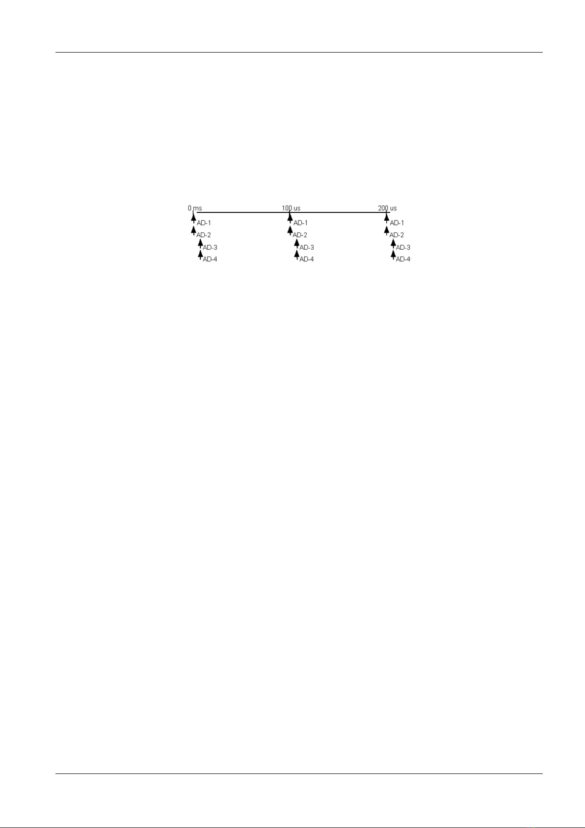
2.5.1 Timing of the AD-/DA-channels
Figure 2.4: Double Staggered Acquisition
Double Staggered Acquisition (EPC 10 USB using the LIH 8+8): The EPC 10 USB uses the double
staggered acquisition mode. To support cophasic acquisition of the two most relevant signals, e.g. the current
and voltage trace of the amplifier, two AD converters are used in parallel. That design results in supporting
cophasic acquisition for 2 AD channels. Also, there is no time delay between two DA channels firing and the time
of acquisition of two 2 cophasic AD channels. In the design of the LIH 8+8, time delays of 5 microseconds per pair
of AD channels will occur, when acquiring more than 2 AD channels.
http://www.heka.com

10 Description of the Hardware
http://www.heka.com

3. Installation
There are several possible installation procedures:
1. Software only, e.g. Patchmaster,Potmaster,Chartmaster or Fitmaster
2. EPC 10 USB and software
3. iTEV 90 USB and software
4. PG 310 USB, PG 340 USB or PG 390 USB and software
5. LIH 8+8 and software
3.1 Installing Software only
Installing software typically requires two steps:
1. Installing the protection key (“dongle”, see chapter 3.5 on the following page)
2. Installing the required software (see chapter 3.6 on page 13)
3.2 Installing Hardware and Software
Installing the hardware and the software requires four steps:
1. Making the physical connection between the hardware and the computer (see chapter 3.4 on the following
page)
2. Installing the protection key (“dongle”, see chapter 3.5 on the next page)
3. Installing the required software (see chapter 3.6 on page 13)
4. Calibrate the hardware
Our software provides the controls and the graphical representation of the amplifier/potentiostat by a “virtual
panel” with “buttons”. Signal display is provided by an oscilloscope-like display. The software provides the
capability of data acquisition and analysis, but can also be used for calibration and self-testing the hardware.
3.3 Conventions
Software: All software packages of HEKA use a common installation procedure. Therefore, throughout the present
manual, we will address the program to be installed as Software, as a place holder for the program you want to
install.
Hardware: Throughout the present manual we will address all amplifiers/potentiostats types as Hardware. We
will explicitly mention the particular amplifiers/potentiostats, where it is required.
MS Windows versions: The Software is supported on Windows 7 (32/64-bit), Windows 8 (32/64-bit) and
Windows 10 (32/64-bit). Throughout the present manual we will address all the above Windows versions as “MS
Windows”. We will explicitly mention the particular MS Windows versions, whenever it is required.
MacOS versions: The Software is supported on MacOS 10.6 or more recent. Throughout the present manual
we will address all the above MacOS versions as “MacOS”. We will explicitly mention the particular MacOS
versions, whenever it is required.

12 Installation
3.4 Connecting the Hardware
1. The Hardware can be installed into a standard nineteen-inch instrument rack or used as a desktop unit.
If installing on a rack, please do not use the Hardware as a shelf to support any other instrument. The
Hardware case was not designed to do this and damage to the front panel will result. To minimize noise,
it is advisable to mount the Hardware away from devices that emit high-frequency signals (i.e monitors,
power supplies, etc).
2. Connect the power cord to the Hardware. The internal power supply used in the Hardware is an auto
switching multi-voltage supply that will operate from 90 Volts to 250 Volts. Make sure that the Hardware
power cord is plugged into a properly grounded AC receptacle. Improper grounding of the Hardware could
result in an electrical shock hazard. It is advisable to plug all equipment into a common outlet strip. This
will minimize power line induced noise in the system.
Note: Please note that the status display of the Clipping and the Digital Bus LED is irrelevant
until the acquisition software has initialized the Hardware.
3. Install the USB cable from the USB connector on the rear panel of the Hardware, labeled “USB”, to an
available USB 2.0 Hi-Speed port on the computer.
Important note: This connection should be made directly to the computers USB 2.0 port and not
to an USB HUB.
4. As soon as the Hardware is detected by the host operating system the appropriate system files will be
initialized and the Hardware will be ready for use.
Note: The host operating system treats the Hardware USB device as it would any Flash mem-
ory device. Therefore, only standard operating system files are required. This provides ease of
installation and flexibility for moving the Hardware from one computer system to another.
5. It is possible to “Join” two units (only for EPC 10 USB and LIH 8+8) to extend the number of analog
channels controlled by one instance of the Patchmaster software. For proper synchronization of the acqui-
sition clocks, a connection between the Master clock output of one unit to the Slave clock input of the other
(connectors located on the rear panel) must be made using standard CAT5 patch cables.
Important note: Please note that the sync clock is a high-frequency signal. The shortest possible
length patch cable should be used.
Note: For “Joining” two units you need to use the PATCHMASTER software from HEKA.
The Hardware is now connected and ready to go.
Note: There will be no calibration files included on a floppy disk or a USB stick. The calibration
files will be stored by default on the mainboard of the device. During the calibration process the old
calibrations files will be substituted by the new ones (see chapter 3.7 on page 14).
3.5 Protection Key (’Dongle’) Installation
To be able to use our Software a protection key (“dongle”) is required. We provide dongles for the USB port
which can be used on MS Windows and MacOS operating systems.
Please download the latest dongle driver software from our website. There you will always find the latest version
of all drivers and software packages.
3.5.1 USB Dongle Installation
Important note: Please install the USB dongle drivers before connecting the USB dongle. After
successfully installing the driver, the USB dongle can be connected.
After the successful installation of the dongle drivers the red LED of the USB dongle should light up continuously.
http://www.heka.com

3.6 Software Installation 13
3.5.1.1 MS Windows
1. Unzip and execute the downloaded file (HASPUserSetup.exe)
2. Follow the installation instructions
3.5.1.2 MacOS
1. Unzip and open the downloaded file (Sentinel Runtime.dmg)
2. Execute Install Sentinel Runtime Environment
3. Follow the installation instructions
3.6 Software Installation
Now, you can install and run the Software. Please pay attention to the supported OS and the according Release
Notes. If you have questions or doubts regarding the hardware/software compatibility please refer to the description
of the product or contact the HEKA support hotline.
Please download the latest software version from our website. There you will always find the latest version of all
drivers and software packages.
3.6.1 MS Windows
Before installing the Software on computers running MS Windows 7 you should make the following precautions:
1. Log in as an administrator
2. Lower the threshold of the ”User Account Control Settings” (Control Panel - User Accounts - Change User
Account Control Settings −>Never Notify)
3. Reboot the system
4. Unzip and execute the downloaded file (e.g. Software Installer.exe)
5. Follow the installation instructions
6. Execute the Software once
7. Undo the settings made in the ”User Account Control Settings”.
If you do not use a MS Windows 7 OS you only have to perform the following steps:
1. Unzip and execute the downloaded file (e.g. Software Installer.exe)
2. Follow the installation instructions
3.6.2 MacOS
1. Unzip and open the downloaded file (Software Installer.dmg)
2. Execute Install Software
3. Follow the installation instructions
Important note: Software version 2x73.5 is the last version supporting processor based on the
PowerPC architecture!
http://www.heka.com
14 Installation
3.7 Calibrating the Hardware
It is advisable to re-calibrate the Hardware once or twice a year or whenever the frequency response of the
amplifier is not accurate or offset currents become noticeable.
Note: The calibration file contains the settings of the digital switches and controls of the amplifier.
These are unique to a given combination of amplifier and probe and cannot be used for another am-
plifier/potentiostat. Therefore, you have to re-calibrate the amplifier/potentiostat, when you replace
the probe! This is a big advantage of our Hardware, since you can use any probe with any ampli-
fier/potentiostat and replace a broken probe without having to send the amplifier/potentiostat in for
re-calibration.
Before starting the Calibration make sure that the Hardware has reached its operational temperature, since the
Calibration depends on temperature. We advice to let the Hardware warm up for 30-60 minutes after powering
it on. The Calibration procedure can be performed with any Software. In the program, go to the Hardware
menu (e.g. EPC 10 USB or PG 340 USB)→Test and Calibrate →Calibrate.
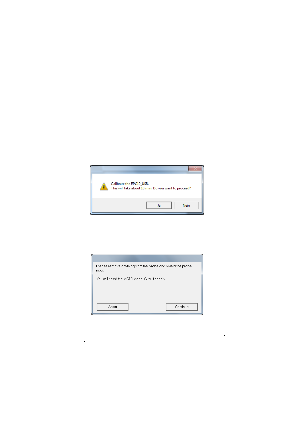
The following Calibration procedure is exemplary for the EPC 10:
The Software will warn you that this procedure may take up to 10 minutes, depending on the speed of your
computer. Go ahead by clicking the ”Yes” button.
Then you are instructed to remove anything from the probe and shield its input: You can use the metallic cap
that came with your Hardware and put it on the BNC connector of the probe to shield it. Please make sure that
really nothing except the metallic cap is connected to the probe (the black GND pin jack should be free) and that
no BNC cables are connected to the inputs and outputs of the Hardware!
At the end of the Calibration, the Software will let you know, whether the Calibration succeeded or failed. If
it succeeded, the program will automatically generate a new calibration (scale) file (SCALE xxxxxx.EPC) and the
C-fast Lookup Table (CFAST xxxxxx.EPC). The files will be stored by default on the mainboard of the Hardware
(EEPROM).
Note: To store these file on your hard drive of your PC please go to the Hardware menu →Test and
Calibrate and change the default setting from Scale from/to EEPROM to Scale from/to Disk.
Note: It is not advisable to change the name of the files, because in that case you would have to
manually load the files during every initialization. It is very advisable to store the files only in the one
place.
http://www.heka.com
Table of contents


