Helios COMBO SPH3600-BL SERIES User manual

i
USER MANUAL
HELIOS COMBO SPH3600/5000-BL
(Multiple Mode Inverter)

ii
© Copyright 2018. Helios New Energy Technology (Australia) Pty Ltd. All rights reserved.
No part of this document may be reproduced or transmitted in any form or by any means without prior
written consent of Helios New Energy Technology (Australia) Pty Ltd
Notice
The purchased products, services and features are stipulated by the contract made between HELIOS and the
customer. All or part of the products, services and features described in this document may not be within the
purchase scope or the usage scope. Unlessotherwise specification inthe contract, all statements, information,
and recommendations in this document are provided “AS IS”without warranties, guarantees or representations
of any kind, either express or implied.
The information in this document is subject to change without notice. Every effort has been made in the
preparation of this document to ensure accuracy of the contents, but all statements, information, and
recommendations in this document do not constitute a warranty of any kind, express or implied.
Helios New Energy Technology (Australia) Pty Ltd
Address:
9 Blue Gum Road
Annangrove, NSW 2156
Australia
Telephone:
+61 (2) 96792284
Mobile:
+61 (0) 414633071
Website:
www.heliosenergystorage.com.au
E-mail:
mail@heliosenergystorage.com.au
HELIOS COMBO SPH3600/5000-BL
Foreword
iii
Foreword
Summaries
Thank you for choosing energy storage inverter SPH-BL(3600-5000) series product!
This document provides a description of energy storage inverter SPH-BL(3600-5000) series product,
including the features, performance, appearance, structure, working principles, installation, operation
and maintenance, etc.
Please save the manual after reading, in order to consult in the future.
Symbol Conventions
The manual quotes the safety symbols, these symbols used to prompt users to comply with safety
matters during installation, operation and maintenance. Safety symbol meaning as follows.
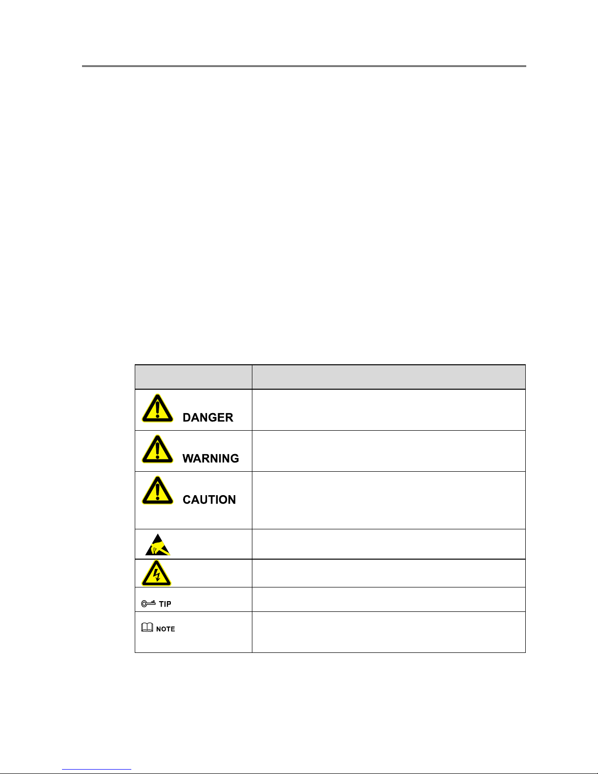
Symbol
Description
Alerts you to a high risk hazard that could, if not avoided, result in
serious injury or death.
Alerts you to a medium or low risk hazard that could, if not avoided,
result in moderate or minor injury.
Alerts you to a potentially hazardous situation that could, if not
avoided, result in equipment damage, data loss, performance
deterioration, or unanticipated results.
Anti-static prompting.
Be care electric shock prompting.
Provides a tip that may help you solve a problem or save time.
Provides additional information to emphasize or supplement
important points in the main text.
Product standard: NB/T 32004-2013

HELIOS COMBO SPH3600/5000-BL
Foreword
iv
Change History
Changes between document issues are cumulative. The latest document issue contains all the changes
made in earlier issues.
Version 1.0 (May 1, 2018)
-First issue

HELIOS COMBO SPH3600/5000-BL
Contents
v
Contents
1 Safety Description......................................................................................................................... 1
1.1 Safety Announcements ......................................................................................................................................1
1.1.1 Safety Instructions....................................................................................................................................1
1.1.2 Device Label Illustartion ..........................................................................................................................3
1.1.3 PV Array Protection .................................................................................................................................4
1.1.4 ESD Protection .........................................................................................................................................4
1.1.5 Grounding Requirements .........................................................................................................................5
1.1.6 Moistureproof Protection .........................................................................................................................5
1.1.7 Warning Mark Setting ..............................................................................................................................5
1.1.8 Electrical Connection ...............................................................................................................................5
1.1.9 Measurement Under Operation ................................................................................................................6
1.2 Operation Requirements ....................................................................................................................................7
1.3 Operation Environment Requirements ..............................................................................................................7
2 Overview.........................................................................................................................................8
2.1 Product Intro ......................................................................................................................................................8
2.1.1 Exterior View ...........................................................................................................................................8
2.1.2 Display Panel............................................................................................................................................9
2.2 Operating mode ...............................................................................................................................................11
3 Installation....................................................................................................................................16
3.1 Unpacking and Checking.................................................................................................................................16
3.2 Installation Preparation....................................................................................................................................16
3.2.1 Installation Environment Requirements .................................................................................................16
3.2.2 Installation Clearance .............................................................................................................................16
3.3 Installation Procedures ....................................................................................................................................17

HELIOS COMBO SPH3600/5000-BL
Contents
vi
4 Electrical Connection..................................................................................................................20
4.1 Operating Principle..........................................................................................................................................20
4.2 Connection Symbol .........................................................................................................................................20
4.3 AC Output Wiring............................................................................................................................................21
4.4 PV Input Wiring...............................................................................................................................................24
4.5 Battery Wiring .................................................................................................................................................27
4.6 COM. Communication Connection .................................................................................................................29
4.7 WiFi/GPRS Connection...................................................................................................................................30
5 Operation Instruction.................................................................................................................33
5.1 Opearaion Announcements..............................................................................................................................33
5.2 Turn on Inverter ...............................................................................................................................................33
5.3 Turn off Inverter ..............................................................................................................................................33
5.4 Monitoring Setting...........................................................................................................................................33
6 Maintenance and Troubleshooting ......................................................................................... 35
6.1 Maintenance.....................................................................................................................................................35
6.2 Troubleshooting ...............................................................................................................................................35
7 Package, Transportation, Storage............................................................................................. 40
7.1 Package............................................................................................................................................................40
7.2 Transportation..................................................................................................................................................40
7.3 Storage .............................................................................................................................................................40
A Technical Specifications ...........................................................................................................41
B WiFi Configuration .................................................................................................................... 45
C Acronyms and Abbreviations ..................................................................................................54
HELIOS COMBO SPH3600/5000-BL
1 Safety Description
1
1 Safety Description
This chapter mainly describes safety description. Prior to performing any work on device, please read
user manual carefully, follow operation and installation instructions and observe all danger, warning
and safety information, which is to avoid human injury and device damage by irregular operations.
1.1 Safety Announcements
This section mainly describes safety announcements during operation and maintenance. For details,
please refer to safety instructions in the relevant chapters.
Before attempting to operate device, please read safety announcements and operation instructions in
this section carefully to avoid accident.
The promptings in the user manual, such as "Danger", "Warning", "Caution", etc. don't include all
safety announcements. They are just only the supplement of safety announcements during operation.
Any device damage caused by violating the general safety operation requirements or safety standards
of design, production, and usage will be out of Xiamen Kehua's warranty range.
1.1.1 Safety Instructions
Multi-channel power supplies power for energy storage inverter. Be careful of electric shock!
HELIOS COMBO SPH3600/5000-BL
1 Safety Description
2
Don't touch terminals or conductors connected with grid to avoid lethal risk!
There is no operational part inside device. Don't open the crust of device, or it may cause electric shock.
Device damage caused by illegal operation is out of the guarantee range.
Device damage or device failure may cause electric shock or fire!
⚫Before attempting to operate device, check that there is no damage or other potential danger in
the device visually.
⚫Check that other external devices or circuit connection is safe.
Before checking or maintenance, it must switch off each route of switch connected with device and
wait for 5 minutes to ensure that device is completely discharged, and then the operation can be
performed.
In case of fire, please use dry power fire extinguisher. If using liquid fire extinguisher, it may cause
electric shock.
HELIOS COMBO SPH3600/5000-BL
1 Safety Description
3
No liquid or other objects are allowed to enter device.
Danger of High Temperature
The surface temperature of device may reach to 60℃. During running, don't touch the surface to avoid
scald.
1.1.2 Device Label Illustartion
The labels on the device contain important information about safety operation. Don't tear them up or
damage them!
Pay attention to labels on the device. The label illustration is as shown in Table1-1.
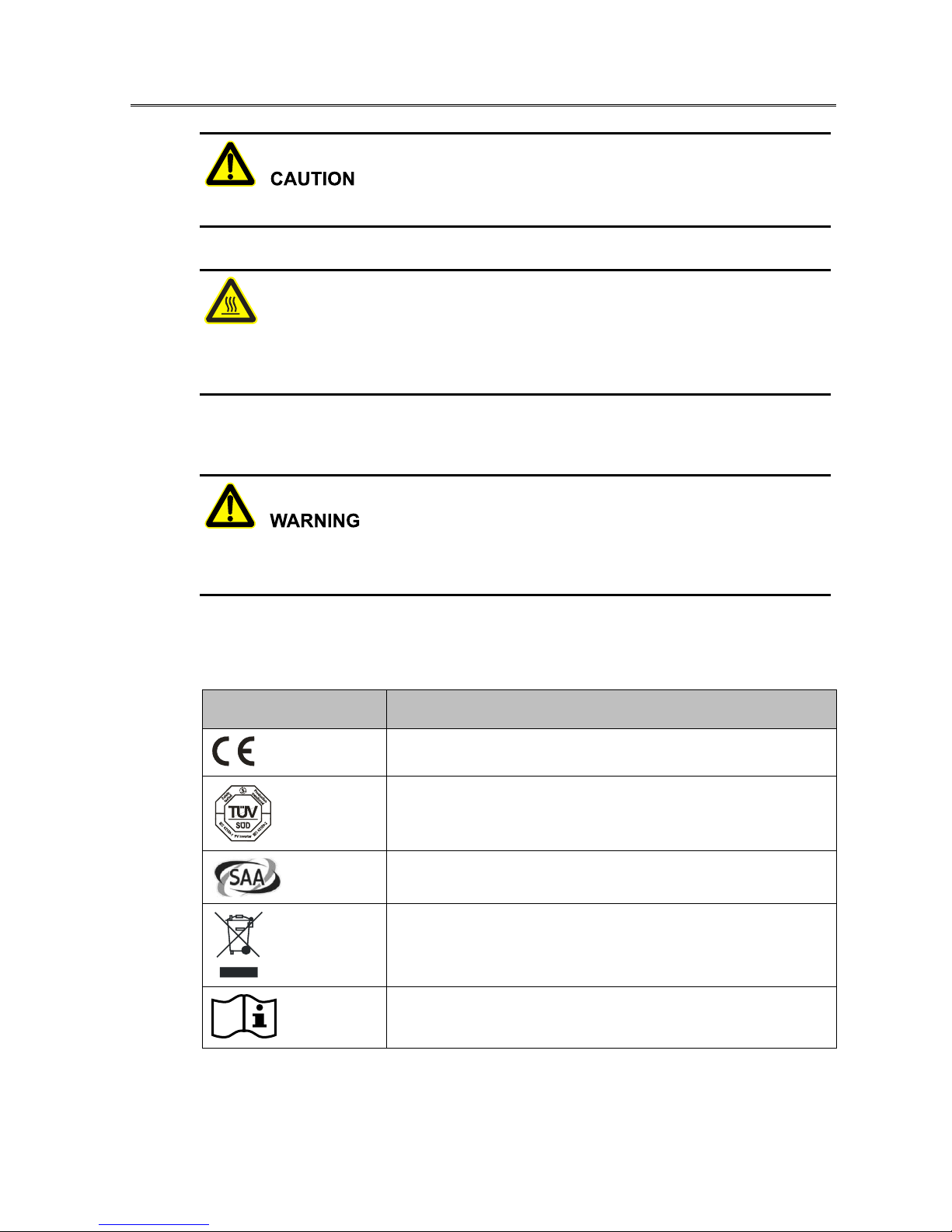
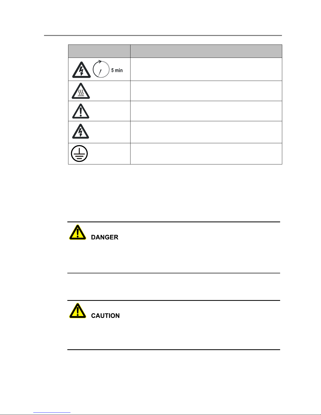
Table1-1 The illustration of device label
Label
Illustration
Pass CE authentication.
Pass TUV authentication.
Pass SAA authentication.
Don't dispose with general garbage. Recycle them by special method.
Read user manual when using device.
HELIOS COMBO SPH3600/5000-BL
1 Safety Description
4
Label
Illustration
Wait for 5 minutes to discharge completely after powering device off.
Hot surface. Don't touch!
Caution!
Multi-channel power supplies power for energy storage inverter. Be
careful of electric shock.
External grounding label.
1.1.3 PV Array Protection
When installing PV array in daytime, it necessary to cover PV array by light-proof material, or the PV
array will generate high voltage under sunshine. If touching PV array accidently, it may cause electric
shock or human injury!
There exists dangerous voltage between the positive and negative of PV array!
When installing device, it must disconnect inverter with PV array completely. Set warning mark here
to avoid reconnecting.
1.1.4 ESD Protection
To prevent human electrostatic damaging sensitive components (such as circuit board), make sure that
you wear a anti-static wrist strap before touching sensitive components, and the other end is well
grounded.

HELIOS COMBO SPH3600/5000-BL
1 Safety Description
5
1.1.5 Grounding Requirements
High leakage risk! Device must be grounded before performing electrical connection. The grounding
terminal must be connected to ground.
⚫When installing device, it must be grounded first. When dismantling device, the grounding wire
must be removed at last;
⚫Don't damage the grounding conductor;
⚫Device should be connected to the protection earth permanently. Before operation, it should
check the electrical connection to ensure the device is grounded reliably.
1.1.6 Moistureproof Protection
Moisture invasion may cause device damage!
Observe the following items to ensure that device works normally.
⚫When the air humidity is more than 95%, don't open the door of inverter;
⚫In the wet or damp weather, don't open device perform maintenance or repair.
1.1.7 Warning Mark Setting
In order to avoid accident for unwanted person gets close to inverter or makes improper operation, it
should observe the following requirements when performing installation, daily maintenance or repair.
⚫Set warning marks where the switches are to avoid turning them on improperly.
⚫Set warning signs or safety warning belt in the operation area, which is to avoid human injury or
device damage.
1.1.8 Electrical Connection
Electrical connection must be performed according to description in the user manual and the electrical
circuit schematic.

HELIOS COMBO SPH3600/5000-BL
1 Safety Description
6
When inverter is working, don't dismantle electrical connection.
The configuration of PV array, grid level, grid frequency, etc. must meet the technical requirements of
device.
Grid-connected generation should be allowed by the local power supply department and the related
operation should be performed by professionals.
All electrical connection must meet the related country and district standard.
Don't touch or replace components except terminals.
1.1.9 Measurement Under Operation
There exists high voltage in the device. If touching device accidently, it may cause electric shock. So,
when performing measurement under operation, it must take protection measure (such as wear
insulated gloves, etc.)
The measuring device must meet the following requirements:
⚫The range and operation requirements of measuring device meets the site requirements;
⚫The connections for measuring device should be correct and standard to avoid arcing.

HELIOS COMBO SPH3600/5000-BL
1 Safety Description
7
1.2 Operation Requirements
The operation and wiring for device should be performed by qualified person, which is to ensure that
the electrical connection meets the related standards.
Don't perform maintenance until disconnecting AC gird, AC load, DC input and battery input with
inverter and wait for 5 minutes to discharge completely.
Before attempting to install, operate and maintain device, the operator must understand the safety
announcements, know correct operations and be trained strictly.
⚫Operator should know the structure and working principle of PV grid-connected generation
system well.
⚫Operator must be familiar with the related country and district standard.
1.3 Operation Environment Requirements
The operation environment may influence the life span and reliability of device. So, please avoid to
use device in following environment:
⚫The place where temperature and humidity beyond the technical specifications.
⚫The place with vibration or impact.

HELIOS COMBO SPH3600/5000-BL
2 Overview
8
2 Overview
This chapter introduces the inverter intro and its operating mode.
2.1 Product Intro
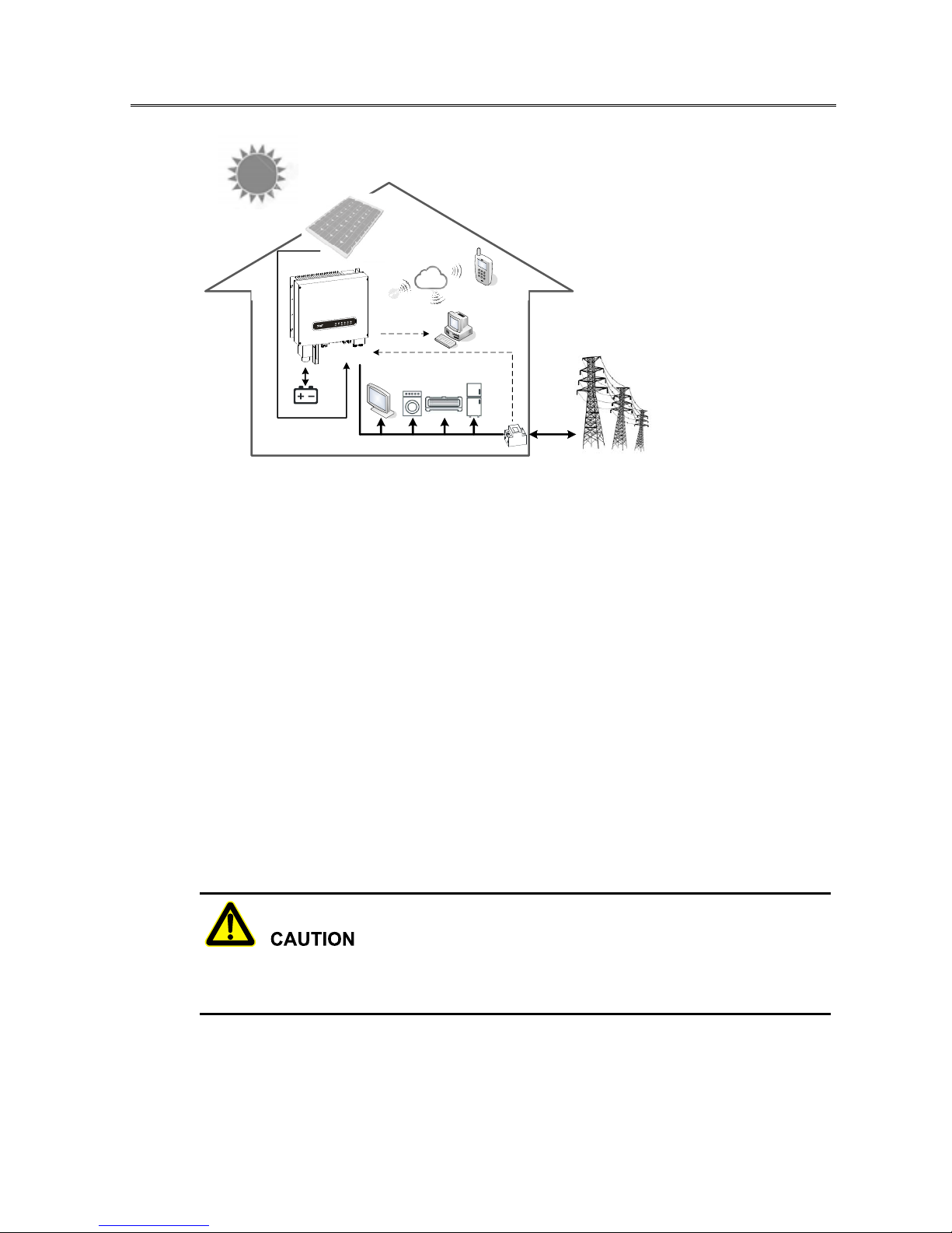
SPH-BL(3600-5000) series inverter is PV energy storage inverter, which mainly applies for household
energy storage system, as shown in Figure2-1.
The household energy storage and management system consists of energy storage inverter, PV array,
batteries, grid, and smart meter(optional), which allows customers to reduce their dependence on grid
and even become energy self-sufficient. The system can achieve an optimal match between the PV
generation, loads and grid and at the same time guarantee the stability of the grid. Moreover, the system
can provide back-up power for important household appliances in case of a power outage.
Figure2-1 PV energy storage system
2.1.1 Exterior View
The exterior view of SPH-BL(3600-5000) series inverter is as shown in Figure2-2.

HELIOS COMBO SPH3600/5000-BL
2 Overview
9
Figure2-2 The exterior view of SPH-BL(3600-5000) series inverter
2.1.2 Display Panel
The display panel of SPH-BL(3600-5000) series inverter is as shown in Figure2-3.
Figure2-3 Display panel
Table2-1 The illustration of display panel
No.
Mark
Meaning
Illustration
○
1
BATT.
Battery status
Green indicator is on, which means battery is
discharging.
Green indicator is cycle on 1s off 1s, which means
battery is charging.
Green indicator is off, which means battery stops
charging and discharging.

HELIOS COMBO SPH3600/5000-BL
2 Overview
10
No.
Mark
Meaning
Illustration
○
2
PV
PV status
Green indicator is on, which means two routes of PV
work normally.
Green indicator is cycle on 0.5s off 0.5s, which means
one route of PV works normally.
Green indicator is off, which means PV stops working.
○
3
GRID
Grid-connected
status
Green indicator is on, which means inverter performs
grid-connected generation.
Green indicator is cycle on 0.5s off 0.5s, which means
inverter performs off-grid generation.
Green indicator is off, which means inverter doesn't
perform grid-connected or off-grid generation.
○
4
COM.
Communication
status
Green indicator is cycle on 0.5s off 0.5s, which means
inverter communicates with PC or WiFi/GPRS.
Green indicator is off, which means inverter doesn't
communicate with PC or WiFi/GPRS.
○
5
RUN
Running status
Green indicator is on, which means inverter works
normally.
Green indicator is cycle on 0.2s off 0.2s, which means
inverter is on the prestart status.
Green indicator is cycle 0.2s off 1.8s, which means
inverter is on the standby status.
Green indicator is off, which means inverter doesn't
power on or has been turned off.
○
6
FAULT
Fault status
Red indicator is on, which means inverter failure.
Red indicator is cycle on 1s off 1s, which means
inverter has an alarm.
Red indicator is off, which means inverter works
normally.

HELIOS COMBO SPH3600/5000-BL
2 Overview
11
2.2 Operating mode
The inverter status can transfer automatically between grid-connected and off-grid mode according to
grid status. In the grid-connected status, there are four operating modes: self-consumption priority,
battery storage priority, peak shaving and energy shift scheduling. When grid is abnormal or failure,
inverter will work in the off-gird emergency mode.
Self-consumption priority
When the energy generated by PV array is sufficient, PV array will supply power for load in advance,
the remaining energy will charge battery. If there still has remaining energy, it will be supplied for grid-
connection generation. When the energy generated by PV array is insufficient, PV array and battery
will supply power for load in advance, as shown in Figure2-4.
Figure2-4 Self-consumption priority
Battery storage priority
If battery doesn't charge fully, PV array and grid will charge battery fully in advance to meet the
emergency power requirements of key loads. When the energy generated by PV array is sufficient
(more than charging energy), it will charge battery in advance, the remaining energy will be supplied
for load. If there still has remaining energy, it will be supplied for grid-connection generation, as shown
in Figure2-5.

HELIOS COMBO SPH3600/5000-BL
2 Overview
12
Figure2-5 Battery storage priority
Peak shaving
If the electricity price makes a big difference in the peak and valley time (In the valley time, the
electricity price of grid-connected generation is cheaper than PV array generation, in the peak time, the
electricity price of grid-connected generation is cheaper than PV array generation), user can set the
charging time and discharging time of battery by WiseEnergy(Equipped monitoring software for PC).
In the peak time, set to battery discharging mode(for household used);in the valley time, set to battery
charging mode to charge battery, as shown in Figure2-6.
User not only can make full use of PV array generation, but also can use electricity price difference in
the peak and valley time properly to improve power consumption strategy and save electricity, which
can provide more economic self-consumption power supply plan.
HELIOS COMBO SPH3600/5000-BL
2 Overview
13
Figure2-6 Peak shaving
Energy shift scheduling
If the electricity price makes a big difference in the peak and valley time(In the valley time, the
electricity price of grid-connected generation is cheaper than PV array generation, in the peak time, the
electricity price of grid-connected generation is more expensive than PV array generation), user can
set the charging time and discharging time of battery by WiseEnergy(Equipped monitoring software
for PC). In the peak time, set to battery discharging mode(Except household used, the remaining energy
will be supplied for grid-connection generation.); in the valley time, set to battery charging mode to
charge battery, as shown in Figure2-7.
User not only can make full use of PV array generation, but also can use electricity price difference in
the peak and valley time properly to improve power consumption and generation strategy and save
electricity, which can provide more economic self-consumption power supply plan and get more
benefits.
Generally, in the energy shift scheduling mode, the battery capacity should be more than 3-4 times of
rated power.

HELIOS COMBO SPH3600/5000-BL
2 Overview
14
Figure2-7 Energy shift scheduling
Off-grid emergency mode
When grid abnormal or failure, inverter will work in the off-gird emergency mode. The inverter can be
regarded as back-up power to supply power for major load, as shown in Figure2-8.
In the off-grid emergency mode, the remaining power supply time depends on battery capacity, load
and battery remaining energy when grid failure. Set to the corresponding working mode according to
different emergency requirements, which is to avoid affecting emergency power supply time for battery
remaining energy isn't enough.
This manual suits for next models
1
Table of contents
Other Helios Inverter manuals


Popular Inverter manuals by other brands

Sofar solar
Sofar solar 3.3KTL-X user manual

MQ Power
MQ Power Whisperwatt DCA180SSI Specifications

FRONIUS
FRONIUS Galvo 1.5 installation instructions

Tripp Lite
Tripp Lite PowerVerter PV 2000FC owner's manual

Delta
Delta E6-TL-US Operation and installation manual

FRONIUS
FRONIUS Symo GEN24 6.0 operating instructions


