manuals.online logo
Brands
  1. Home
  2. •
  3. Brands
  4. •
  5. Delta
  6. •
  7. Inverter
  8. •
  9. Delta E6-TL-US Specification sheet

Delta E6-TL-US Specification sheet

US
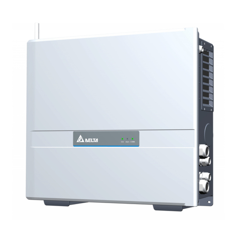
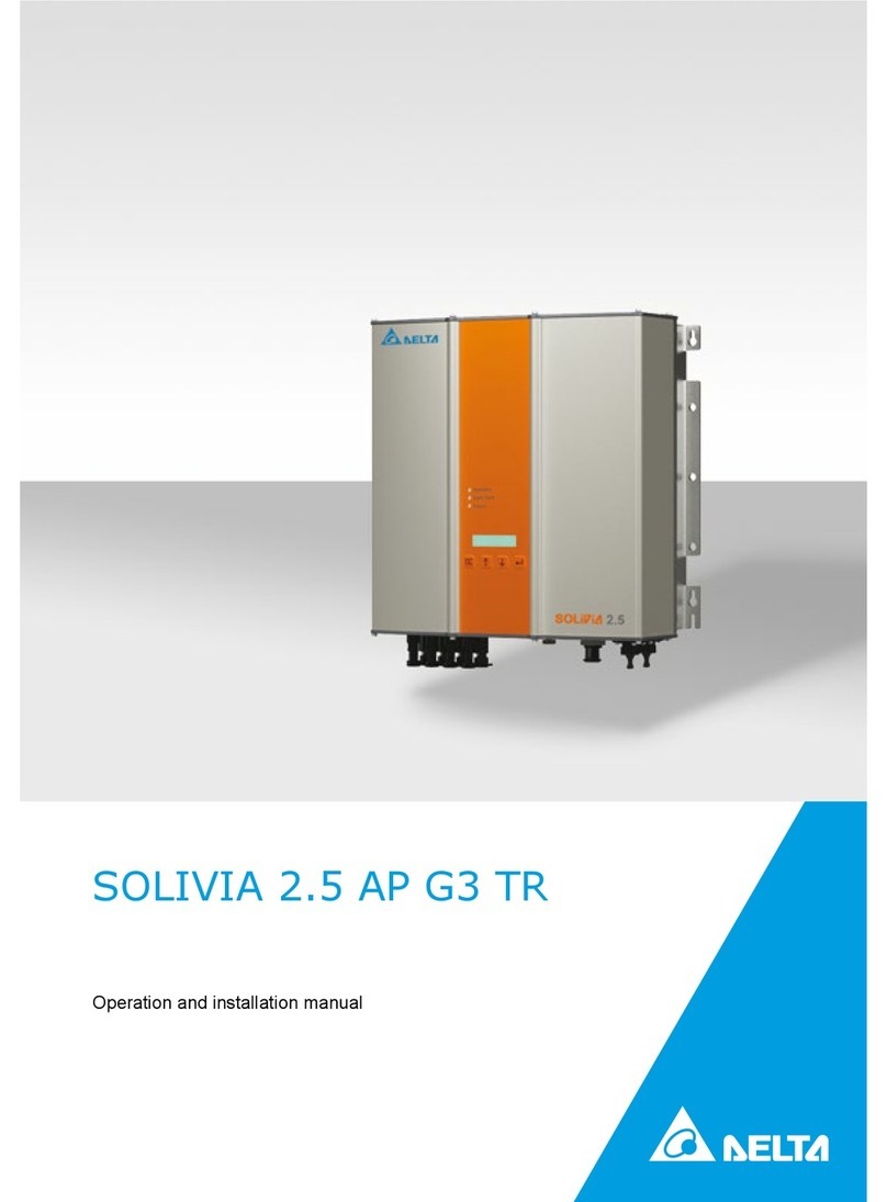
Operation and Installation Manual for Delta E Series
E6-TL-US
E8-TL-US
1
This manual is subject to change.
Please check our website at http://www.delta-americas.com/SolarInverters.aspx
for the most up-to-date manual version.
© Copyright – DELTA ELECTRONICS (SHANGHAI) CO.,LTD. - All rights reserved.
This manual accompanies our equipment for use by the end users. The technical instructions and illustrations contained in this ma-
nual are to be treated as condential and no part may be reproduced without the prior written permission of DELTA ELECTRONICS
(SHANGHAI) CO.,LTD. Service engineers and end users may not divulge the information contained herein or use this manual for
purposes other than those strictly connected with correct use of the equipment. All information and specications are subject to
change without notice.
2
Table of Contents
1 General safety instructions 4
1.1 Safety symbols and terminology definitions 5
1.2 Safety Instructions 6
2 Introduction 7
2.1 System 8
2.2 Data evaluation and communication 10
2.3 Technical structure of the solar inverter 10
2.4 Ambient temperature 11
2.5 Inverter PV input DC voltage range 12
2.6 Efficiency 12
2.7 Equipment overview 13
2.8 Inverter type and safety labels 14
3 Installation 17
3.1 Visual inspection 19
3.2 Installation location 19
3.3 Mounting the inverter 20
3.4 Required torques for Delta E series 22
4 Electrical connections 23
4.1 General safety 23
4.2 Utility AC voltage 24
4.3 AC circuit breaker requirements 26
4.4 Grounding electrode conductor (GET) 26
4.5 Lightning and surge protection 26
4.6 Multiple inverters 26
4.7 PV string considerations 26
4.8 Inverter connections 27
4.8.1 General information 27
4.8.2 Opening the wiring box cover 29
4.8.3 Wiring box conduit plugs 30
4.8.4 PV array string input connections 32
4.8.5 PV switch LOCK out and TAG out procedure 34
4.8.6 Battery wire connections 35
4.8.7 Energy meter connections 36
4.8.8 Energy meter connections (Inverter Side) 38
3
4.8.9 Inverter AC output wire connections 39
4.8.10 ATS wire connections 44
4.8.11 Inverter RS485 communication connections 45
4.8.12 Wi-Fi antenna connection 47
5 Commissioning the PV system 48
5.1 LED Indication 49
5.1.1 Introduction 49
5.1.2 LED Status 49
5.1.3 LED Message 50
5.2 Button 51
5.2.1 Reset button 51
5.2.2 Dark start button 51
Reset button 51
5.3 Inverter turn-on procedure 52
5.4 Inverter turn-off procedure 52
Dark start button 52
5.5 Delta E series APP(Android) Manual 53
5.5.1 Introduction 53
5.5.2 Installation 53
5.5.3 Connection 53
5.5.4 Functions 54
6 Production information 59
7 Repair 59
8 Decommissioning, transport, storage, disposal 60
8.1 Decommissioning 61
8.2 Packaging 61
8.3 Transport 61
8.4 Storage 61
8.5 Dispose 61
9 Certificate and technical data 61
9.1 Certificate 61
9.2 Technical data 62
9.3 FCC compliance information 64
9.4 Canada compliance information 65
10 Warranty 65
11 Appendix 65
12 Glossary 66
4
This manual contains important instructions for Delta models E6-TL-US and E8-TL-US that should
be followed during installation and maintenance of the inverter.
Delta models E6-TL-US and E8-TL-US inverters are designed and tested to meet all applicable
North American and International safety standards. However, like all electrical and electronic equip-
ment, safety precautions must be observed and followed during installation and operation of the
Delta E series inverters to reduce the risk of personal injury and to ensure a safe installation.
Installation, commissioning, service, and maintenance of Delta models E6-TL-US and E8-TL-US
inverters must only be performed by qualied personnel that are licensed and/or satisfy state and
local jurisdiction regulations.
Before starting installation or commissioning of the Delta models E6-TL-US and E8-TL-US, read
through the entire manual and note all DANGER! WARNING! CAUTION!, and NOTICE! statements.
All US electrical installations must comply and be in accordance with all the state, local, utility regu-
lations, and National Electrical Code ANSI/NFPA 70.
For installations in Canada, please ensure these are done in accordance with applicable Canadian
standards.
Ce guide contient d’importantes instructions concernant les onduleurs solaires Delta E6-TL-US
,and E8-TL-US qui devant être observées au cours de l’installation et de l’entretien de l’onduleur.
Les onduleurs solaires Delta E6-TL-US and E8-TL-US sont conçus et testés pour répondre à toutes
les normes de sécurité nord-américaines et internationales applicables. Cependant, comme pour
tous les équipements électriques et électroniques, des mesures de sécurité doivent être respectées
et observées durant l’installation et l’exploitation des onduleurs E series de Delta an de réduire le
risque de préjudice corporel et de garantir la sécurité de l’installation.
L’installation, la mise en service, l’entretien et la maintenance des onduleurs solaires Delta E6-TL-
US and E8-TL-US doivent être entreprises uniquement par un personnel qualié autorisé et/ou
répondant aux critères des règlements locaux ou nationaux applicables.
IMPORTANT SAFETY INSTRUCTIONS
SAVE THESE INSTRUCTIONS
1 General safety instructions
5
1.1 Safetysymbolsandterminologydenitions
Lisez l’intégralité du manuel et prenez note de toutes les déclarations relatives à la sécurité sous les
rubriques intitulées DANGER ! AVERTISSEMENT ! PRUDENCE ! et AVIS ! avant de commencer
l’installation ou la mise en service des onduleurs solaires E6-TL-US and E8-TL-US.
Toutes les installations électriques nord-américaines doivent être conformes et respecter tous les
règlements des services publics, nationaux, locaux ainsi que le National Electrical Code ANSI/
NFPA 70.
Pour toute installation au Canada, veuillez vous assurer que les installations sont conformes aux
normes canadiennes applicables.
DANGER indicates a hazardous situation which, if not avoided,
will result in death or serious injury.
DANGER indique une situation dangereuse qui, si elle n’est pas
évitée, est susceptible de provoquer un décès ou des blessures
graves.
WARNING indicates a hazardous situation which, if not avoided,
could result in death or serious injury.
AVERTISSEMENT indique une situation dangereuse qui, si elle
n’est pas évitée, est susceptible de provoquer un décès ou des
blessures graves.
CAUTION indicates a hazardous situation which, if not avoided,
could result in minor or moderate injury.
PRUDENCE indique une situation dangereuse qui, si elle n’est
pas évitée, est susceptible de provoquer des blessures légères
ou de degré moyen.
NOTICE indicates a situation that can result in property damage
if not avoided.
AVIS indique une situation susceptible de provoquer des dom-
mages à la propriété, si elle n’est pas évitée.
INFORMATION provided that when known and used will ensure
optimal operation of the system.
La connaissance et l’utilisation des INFORMATIONS fournies ga-
rantissent un fonctionnement optimal du système.
INFORMATION!
INFORMATIONS!
NOTICE!
AVIS!
6
The inverter installation must be performed by an authorized electrician in accordance with the local
and National Electrical Code ANSI/NFPA 70 and OSHA requirements.
• The inverter section contains no user-serviceable parts. For all service and maintenance,
the inverter should be returned to a Delta Authorized Service Center.
• Read all of these instructions, cautions, and warnings for the Delta E series inverter and
associated PV array documentation.
• Before connecting the Delta E series inverter to the AC distribution grid, approval must be
received by the appropriate local utility as required by national and state interconnection
regulations, and must be connected only by qualied personnel.
• In operation, the inverter wiring and connections can have hazardous high voltages and
currents present, thus only authorized and qualied personnel shall install and/or maintain
the inverter.
• In some operation instances, the inverter chassis and heatsink surfaces may become hot.
• PV solar arrays produce hazardous voltages and currents when exposed to light which
can create an electrical shock hazard. Use dark opaque sheets to cover the PV solar array
before wiring or connecting cable terminations.
1.2 Safety Instructions
HIGH VOLTAGE WARNING! Indicates hazardous high voltages
are present, which, if not avoided, will result in death or serious
injury. Thus, only authorized and trained personnel should install
and/or maintain this product.
AVERTISSEMENT HAUTE TENSION! indique la présence de
hautes tensions présentant un danger susceptibles de provoquer
un décès ou des blessures graves si elles ne sont pas évitées.
Par conséquent, l’installation et/ou l’entretien de ce produit doi-
vent être entreprises uniquement par un personnel autorisé et
formé.
Hot surface
Surface chaude
Equipment grounding conductor (PE)
(PE) Équipement conducteur de terre
Wait for a prescribed amount of time before engaging in the indi-
cated action.
Patientez le délai requis avant d’entreprendre l’action indiquée.
7
L’installation et la mise en service doivent être e󰀨ectuées par un électricien autorisé conformé-
ment aux exigences locales et nationales ainsi qu’au National Electrical Code ANSI/NFPA 70 et
condition nécessaire OSHA.
• L’onduleur ne comporte aucune pièce pouvant être réparée par l’utilisateur. An de réduire
les risques de choc électrique, contactez le personnel d’entretien qualié de l’usine à propos
des opérations d’entretien.
• Lisez toutes les instructions, rubriques Prudence et Avertissement de l’onduleur Delta E
series , ainsi que la documentation sur le panneau photovoltaïque associé.
• Avant de connecter l’onduleur solaire Delta E series au réseau de distribution du courant
alternatif (CA), une autorisation doit être obtenue de la part des services publics locaux de
tutelle, conformément aux règlements concernant l’interconnexion nationale et locale. La
connexion ne doit être e󰀨ectuée que par un personnel qualié.
• Des courants et des tensions de hautes intensités dangereuses peuvent être présents dans
le câblage et les connexions de l’onduleur en marche, par conséquent, l’installation et/ou la
maintenance de l’onduleur doivent être entreprises uniquement par un personnel autorisé et
qualié.
• Sous certains régimes de fonctionnement, le châssis de l’onduleur et les surfaces des dis-
sipateurs de chaleur peuvent devenir chaud.
• Les panneaux solaires photovoltaïques produisent tensions et courants dangereux lorsqu’ils
sont exposés à la lumière et constituent un danger de choc électrique. Couvrez le panneau
solaire photovoltaïque à l’aide de morceaux de tissu opaques et foncés avant tout câblage
ou connexion des terminaisons de câble.
The inverter not only meets the safety requirements of UL 1741, but also complies with the
specications of UL 1741 SA for Grid Support Utility Interactive Inverters that support a more
stable utility grid. Delta E series were testing to the UL 1741 SA for CA Rule 21 and
other Source Requirement Document (SRD) including ‘PG&E Electric Rule No.21 Hh’, ‘SCE
Rule21 Hh’, ‘SDGE Rule21 Hh’ and ‘HECO SRD-UL-1741-SA-V1.1’.
In the following technical description, the precise functions are explained to the installer, as well
as the user, which are required for the installation, operational start-up and handling of the solar
inverter.
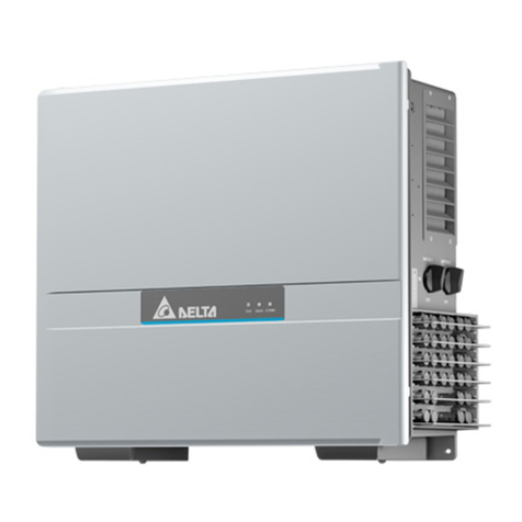
With this device you have acquired a solar and energy storage inverter for connection of both pho-
tovoltaic systems and energy storage systems to the grid. This solar and energy storage inverter
is characterized by an advanced housing design and state-of-the-art high-frequency technology,
which enable the highest levels of e󰀩ciency.
The solar and energy storage inverter includes series monitoring units, such as anti-islanding
protection, display, RS485 (EIA485) interfaces.
The inverter is usable indoor and outdoor. It fullls the directives of ANSI/NFPA 70, NEC 690.5,
UL 1741, UL 1741 SA,IEEE 1547 and IEEE 1547.1 for parallel operation of power generation
plants on low-voltage network of regional electrical utility companies.
.
The function of the anti-islanding protection (automatic isolation point for in-plant generation sys-
tems) stipulates compliance with the specications of UL 1741,UL 1741 SA and IEEE 1547.
2 Introduction
8
In the following system level technical description, the precise functions are explained to the
installer, as well as the user, which are required for the installation, operational start-up and han-
dling of the solar inverter.
The content of renewable energy with respect to overall power consumption worldwide is increas-
ing annually by approximately 25%. The reason for this rise can be primarily attributed to the con-
stantly increasing demand for power, the increasing interest in environmentally friendly technolo-
gies, as well as the increasing costs of non-renewable energy.
By the use of renewable energy sources, the earth‘s atmosphere can be enormously relieved of
increases in CO2 and other harmful gases which result from power generation.
The solar inverter converts direct current from the solar cells into alternating current. This enables
you to feed your self-produced solar energy into the public grid.
Thanks to e󰀩cient MPP tracking, maximum capacity utilization of the solar energy plant is en-
sured even in cases of misty and cloudy skies.
The string concept means that PV modules are always connected in series (in a string) and/or
that strings with the same voltage are connected in parallel to the solar inverter with the aim of
signicantly reducing the photovoltaic system’s cabling requirements.
The fact that the modules are connected in strings also means that the photovoltaic system can be
perfectly matched to the solar inverter’s input voltage range.
The inverter is transformerless type without galvanic isolation. Therefore, the inverter may only be
operated with ungrounded PV arrays. Furthermore, the PV array must be installed in accordance
with the NEC690.35 (Ungrounded Photovoltaic Power Systems) and the locally valid regulations for
ungrounded PV arrays. Additionally, the PV array (PV modules and cabling) must have protective
insulation and the PV modules used must be suitable for use with this inverter. PV modules with
a high capacity to ground may only be used if their coupling capacity does not excessed 1,200 nF
with 60Hz grid.
2.1 System
If a high voltage(HV) battery is connected to the Delta E series inverter, it must be ac-
tivated before use. This setting can be done in factory test or via APP after installation.
HV battery communicates with Mario E series inverter through RS485 or CAN. And the
battery must comply with the specications of UL1973.
For DC-couple system, PV panel works in MPPT mode or power reduction mode ac-
cording to system orperationa mode. And the maximum number of PV string is three.
For AC-couple system, there may be no solar module connected to Delta E series
inverter, and the PV power option will be deactivated.
The Delta E Series inverter manages battery and system energy.
Delta E Series
PV Panel
HV Battery
9
CAN/
RS485
RSD
RSD
RSD
PV2
PV1
PV3
Android/IOS
APP
BLE
Delta E Series
HV Battery
ATS
Grid
Main Load
Panel
Critical
Load Panel
Meter
Load
Delta Cloud Utility Enterprise Systems
Other Cloud
DC Power
AC Power
Communication
Cloud
Figure 1: System overview
10
2.2 Data evaluation and communication
The integrated interface, processing and communication of the device enables easy operation of
the solar inverter. Monitoring of the operational status and signaling of operational failures are capa-
ble of being called up over the interface. The data interfaces enable the downloading of data which
can be evaluated with the aid of a PC system and allow continuous recording of operating data.
The best way of accessing this functionality is via a monitoring system connected to your inverter.
2.3 Technical structure of the solar inverter
The RSD provides an automatic disconnect of residential or small commercial PV
systems, fully compliant with the Rapid Shutdown requirements of NEC 2014 Article
690.12.
Meter is used by the inverter for import / export or consumption readings, and manages
the battery charge / discharge accordingly for smart energy management applications,
for example self-consumption, zero-export or TOU. Meter reports its electricity measur-
ing value to inverter via RS485 following Modbus.
240V / 208V grid are supported, and it can be congured via APP.
A very powerful tool for monitoring, conguration or diagnosis. APP is connected to
inverter via BLE.
Delta E series can exchange with Delta cloud using gateway (Wi-Fi / Ethernet / Cellular)
which can be installed in the AC wiring box of inverter. Also, gateway can push data
directly to customer’s cloud or third-party cloud.
There are several groups of switch mounted inside Auto Transfer Switch(ATS), and it
can be used for realizing automatic transfer from grid connection mode to o󰀨 grid mode,
or from o󰀨 grid mode to grid connection mode.
The photovoltaic voltage is adjusted so that the maximum power output of the PV modules is also
achieved with di󰀨erent solar irradiation levels and temperatures (MPP-Tracking). These inverters
have quite wide MPP range of suit for variety of PV modules by a variety of manufacturers. Mea-
sures must be taken to ensure that the maximum no- load voltage is never exceeded. Please note
that the maximum no-load voltage will occur at the lowest temperatures anticipated. You will nd
more detailed information about temperature dependency in the data sheet for the PV modules.
The high-quality aluminum casing corresponds to protection degree Type 4 and is protected by an
anti-corrosion nish. The heat sink on the Delta solar and energy storage inverter
is designed in such a way that operation of the inverter is possible at ambient temperatures from
-22°F to +113°F (-30°C to +45°C) at full power and optimal e󰀩ciency for either 240 Vac or 208 Vac
AC grids.
ATS
RSD
Grid
Meter
Android/iOS APP
Delta Cloud
11
Metal ns designed into the rear side of the inverter chassis are used to dissipate heat and protect
the unit. An internal temperature control protects the interior of the device. In case of high ambient
temperatures, the maximum transferable power is limited.
The inverter is controlled by microcontrollers which provide interface communication and the values
and messages by APP or cloud
AC grid monitoring is done by an independent dedicated micro controller set up to meet the require-
ments of UL 1741,UL1741 SA / IEEE 1547. This enables a connection of the solar inverter to the
in-house grid.
Operator protection requirements are met by electrically isolating the grid from the PV module. The
electrical isolation between the grid and the PV module is equivalent to basic insulation. Maximum
operator protection is ensured by reinforced isolation between the grid, PV modules, bettery and
accessible interfaces (display, RS485 interface ). Relevant standards concerning electromagnetic
compatibility (EMC) and safety are fullled.
The inverter is functional in grid-parallel operation exclusively. An automatically anti-islanding func-
tion, which was accepted by a certication agency, guarantees secure disconnection in case of
circuit isolation or interruptions in power supply and avoid isolated operation.
The DC arc-fault circuit interrupt (AFCI) is integrated into E6-TL-US and E8-TL-US . It complies
the requirement as Type 1 device in UL1699B standard, series arc faults can be detected.
The inverter can be operated in an ambient temperatures from 22 °F to 149 °F (-30°C to +65°C).
The following diagram illustrates how the output power of the solar inverter is reduced automati-
cally in accordance with ambient temperature.
The device should be installed in a well-ventilated, cool and dry location.
Due to tolerrance of temperature sensor and e󰀩ciency di󰀨erence under di󰀨erent PV voltage, this
derating curve may be a litte di󰀨erent from actual behaviors of unit.
2.4 Ambient temperature
Figure 2: Typical derating curve of Delta E series inverter
12
2.5 Inverter PV input DC voltage range
Figure 3: Voltage Range of E6-TL-US / E8-TL-US
The best e󰀩ciency of the solar inverter is obtained at input voltages > 320V for 208V grid, and
input voltages > 380V for 240V grid. The curve is obtained at 240V from PV port to utility grid.
Figure4:E󰀩ciencyplotofE6-TL-US
2.6 E󰀩ciency
13
Figure5:E󰀩ciencyplotofE8-TL-US
2.7 Equipment overview
(1) Inverter Power Box
(2) Wiring Box Cover
(3) LED indicator
(4) Mounting Plate
(5) Wiring Box
(6) Lockable DC Disconnect
(7) Conduit Plugs
Figure 6: Exterior view of nverter main components
(1)
(3)
(4)
(5)
(2)
(7)
(6)
14
A further description of the equipment features:
(1) Solar Inverter Power Box - This is the inverter section of the assembly. This section is sealed
at the factory and there are no user-serviceable parts inside. All wiring to install the inverter is
done in the wiring box.
(2) Wiring Box Cover - This is the cover for the wiring compartment.
(3) LED indicator - The ve LED lights indicate errors or status as described in section 8.
(4) Mounting Plate - The inverter ships with a mounting plate that allows easily assembly of the
inverter to a wall.
(5) Wiring Box - This is the compartment where all the wiring for the inverter inputs and outputs
plus the RS485 communication are done.
(6) Lockable DC Disconnect - The DC disconnect is lockable per the UL code and allows for the
DC power to be switched o󰀨 to the inverter
(7) Conduit Plugs - There are 5 - 3/4“ conduit openings and 2 - 1/2“ conduit openings. Each
conduit opening comes tted with a conduit plug that should be removed before installing conduit
ttings. Conduit ttings need to be water tight with either NEMA 4, 4X, 6, or 6X rated, and insula-
ted type is preferred.
2.8 Inverter type and safety labels
The type label is shown in gure 7. Di󰀨erent type labels can be found on the models E6-TL-US
and E8-TL-US. The inverter serial number can be found on the type label.
The main caution labels in English and French are on the left side of the inverter.
15
Figure 7: Location of type label
E6-TL-US
DC Max. System Voltage:
DC Operating Voltage Range:
DC Full Power MPPT Range:
DC Max. Input Current per String:
AC Nominal Output Voltage:
AC Operating Voltage Range:
AC Max. Continuous Output Current:
AC Max. Continuous Output Power:
AC Nominal Output Frequency:
AC Operating Frequency Range:
Output Power Factor:
This device complies with part 15 of FCC rules.
Operation is subject to the following two conditions:
(1)this device may not cause harmful interference,and
(2)this device must accept any interference received,
including interference that may cause undesired operation.
GPI60210033P
Rev.:XX
Date Code:YYWW
S/N:MMMYYWWRRZZZZ Made in China
240436
480 V
50-480 V
200-480 V
12 A
60 Hz
59.3-60.5 Hz
0.99(0.85i-0.85c adj.)
Type 1
208 V
183-228 V
24 A
5472 W
240 V
211-264 V
24 A
6000 W
Enclosure Type: Type 4
Grid Support Utility-Interactive Transformerless Inverter
Ambient Temperature: -30 - +65°C Derating >45°C
CSA C22.2 NO.107.1-01 UL1741 UL1699B
Battery DC Max.Input/output Voltage:
Battery DC Operating Voltage Range:
Battery DC Max.Input/output Current:
480 V
350-480 V
15 A
5min
E8-TL-US
This device complies with part 15 of FCC rules.
Operation is subject to the following two conditions:
(1)this device may not cause harmful interference,and
(2)this device must accept any interference received,
including interference that may cause undesired operation.
GPI76210034P
Rev.:XX
Date Code:YYWW
S/N:MMMYYWWRRZZZZ Made in China
240436
Type 1
Enclosure Type: Type 4
Grid Support Utility-Interactive Transformerless Inverter
Ambient Temperature: -30 - +65°C Derating >45°C
CSA C22.2 NO.107.1-01 UL1741 UL1699B
480 V
50-480 V
270-480 V
12 A
60 Hz
59.3-60.5 Hz
0.99(0.85i-0.85c adj.)
PV DC Max System Voltage:
PV DC Operating Voltage Range:
PV DC Full Power MPPT Range:
PV DC Max. Input Current per String:
AC Nominal Output Voltage:
AC Operating Voltage Range:
AC Max. Continuous Output Current:
AC Max. Continuous Output Power:
AC Nominal Output Frequency:
AC Operating Frequency Range:
Output Power Factor:
208 V
183-228 V
32 A
7296 W
240 V
211-264 V
32 A
8000 W
Battery DC Max.Input/output Voltage:
Battery DC Operating Voltage Range:
Battery DC Max.Input/output Current:
480 V
350-480 V
15 A
5min
WARNING
AVERTISSEMENT
*Cancer and Reproductive Harm - www.P65Warnings.ca.gov.
*Risk of electric shock. Do not remove or destroy this label.
*Do not remove the cover. No user serviceable parts inside. Refer servicing to
qualified service personnel.
*Both AC and DC voltage sources are terminated inside this equipment.
Disconnect each circuit individually before servicing.
*When the photovoltaic array is exposed to light, it supplies DC voltage to the
equipment.
*Risk of electric shock from energy stored in capacitor. Do not remove cover until 5
minutes after disconnection all sources of supply.
*Normally grounded conductors may be ungrounded and energized when a ground
fault is indicated.
*Voltage and frequency trip points are factory set to current UL1741.2 and IEEE
1547/1547.1 standards.
*Warning: More than one live circuit. See diagram in manual.
*Hot surfaces. To reduce the risk of burns, do not touch.
*Cancer et effet nocif sur la reproduction -
www.P65Warnings.ca.gov.
*Risque de choc électrique,ne pas enlever ou détruire cette étiquette.
*Pour le raccordement voir le manuel.
*Le boîtier ne doit en aucun cas
ê
tre ouvert.Aucun composant interne n´est à
entretenir.Reportez-vous à un technicien qualifé pour tout entretien.
*Les deux sources de tension CA et CC sont résiliées à
l`
intérieur de cet
équipement.Débranchez chaque circuit individuel avant tout entretien.
*Quand les panneaux photovoltaïque sont expos
és à
la lumière,ils fournissent une
tension en courant continu à l
´é
quipement.
*Risque de choc
é
lectrique à partir d
´é
nergie stockée dans les
condensateurs.Retirer le couvercle du boîtier au moin 5 minutes après avoir
d
ébranché toutes les sources d´approvisionement.
*Attention:
Risque de choc
é
lectrique.Les conducteurs DC de cesystème
photovoltaïque ne sont pas fondées et peuvent être alimentés.
Attention:Risque de choc
é
lectrique.Les conducteurs DC de cesystème
photovoltaïque ne sont normalement mis à la terre,mais deviendra intermittence
terre sans indication lorsque le variateur mesure le photovoltaïque isolement.
*Surface chaude.Pour réduire le risque de brûlures ne pas toucher.
16
Figure 8: Dimensions of Delta E Series
inverters
PV PV PV PV PV PV BAT+ BAT-
1+ 2+ 3+ 1- 2- 3-
(4) (7)
(2)(1)
(1) PV terminals
(2) BAT terminals
(3) Reset button
(4) Grounding
(6)
(5) AC side L1
(6) AC side Netural
(7) AC side L2
(8) RS485 communication ports
(8)
(5)
Figure 9: Wiring box of E series inverters
(3)
17
3 Installation
Read all of these instructions, cautions, and warnings for the Delta
E series inverter and associated PV array documentation.
Lisez toutes les instructions, rubriques Prudence et Avertissement
de l’onduleur Delta E series , ainsi que la documentation sur le
panneau photovoltaïque associé.
Installation and commissioning must be performed by a licensed
electrician in accordance with local, state, and National Electrical
Code ANSI/NFPA 70 requirements.
L’installation et la mise en service doivent être e󰀨ectuées par un
électricien autorisé conformément aux exigences locales et natio-
nales ainsi qu’au National Electrical Code ANSI/NFPA 70.
The installation and wiring methods used in the installation of this
inverter in the U.S. must comply with all US National Electric Code
requirements (NEC) and local AHJ inspector requirements. In
Canada, the installation and wiring methods used must comply
with the Canadian Electric Code, parts I and II, and the local AHJ
inspector requirements. System grounding when required by the
Canadian Electrical Code, Part 1, is the responsibility of the
installer.
Les méthodes d’installation et de câblage utilisées lors de
l’installation de cet onduleur aux États-Unis doivent être conformes
à toutes les exigences du National Electric Code (NEC) nord-
américain et à celles des services d’inspection locaux de l’AHJ. Au
Canada, les méthodes d’installation et de câblage utilisées doivent
être conformes au Canadian Electric Code, parties I et II et aux
exigences des services d’inspection locaux l’AHJ. L’installateur est
responsable de la mise à terre du système lorsque requise par le
Canadian Electrical Code, Partie 1.
WARNING!
AVERTISSEMENT!
WARNING!
AVERTISSEMENT!
WARNING!
AVERTISSEMENT!
Terminals in Figure 9 Wire size permitted Torque
3(Grounding) 12 - 8 AWG (4 - 9 mm2) 16 in-lbs
Required torques for wiring box terminals
Table 1: Required torques for wiring box terminals
* Exception: Specied torque marked on the terminal block.
18
WARNING!
AVERTISSEMENT!
The secondary short-circuit current rating is increased at the trans-
fer connection point to the public electricity supply system by the
nominal current of the connected solar inverter.
Le courant nominal secondaire du court-circuit est augmenté au
point de connexion du transfert vers le réseau électrique public par
le courant nominal de l’onduleur solaire connecté.
To reduce the risk of re, connect only to a circuit provided with
branch circuit overcurrent protection in accordance with the Natio-
nal Electrical Code, ANSI/NFPA70.
An de réduire les risques d’incendie, e󰀨ectuez une connection
uniquement avec un circuit équipé d’une protection contre les
surintensités des circuits de dérivation, conformément au National
Electrical Code, ANSI/NFPA70.
This unit or system is provided with xed trip limits and shall not be
aggregated above 30KW on a single point of common connection.
Cet appareil ou système est fourni avec des limites de déclenche
xes et ne doit pas être agrégé au-dessus de 30KW sur un seul
point de connexion commun.
In order to be able to carry out an energy measurement, a KWH
revenue meter must be attached between the networks feed-in
point and the solar inverter.
An de pouvoir mesurer la quantité d‘énergie électrique consom-
mée, un compteur électrique (kWh) devra être installé entre le point
d’entrée du réseau d‘alimentation et l’onduleur solaire.
INFORMATION!
INFORMATIONS!
CAUTION!
PRUDENCE!
CAUTION!
PRUDENCE!
CAUTION!
PRUDENCE!
These servicing instructions are for use by qualied personnel only.
To reduce the risk of electric shock, refer all servicing to factory
qualied service personnel. No user service parts are contained
inside the inverter.
Les instructions concernant la maintenance sont destinées à être
utilisées uniquement par un personnel qualié. An de réduire les
risques de choc électrique, contactez le personnel d’entretien qua-
lié de l’usine à propos des opérations d’entretien. L’onduleur ne
comporte aucune pièce pouvant être réparée par l’utilisateur.

This manual suits for next models

2

Other Delta Inverter manuals

Delta SCC-30A-PWM-LCD User manual

Delta

Delta SCC-30A-PWM-LCD User manual

Delta SI 5000 Specification sheet

Delta

Delta SI 5000 Specification sheet

Delta M15A-220 Specification sheet

Delta

Delta M15A-220 Specification sheet

Delta M88 Series Specification sheet

Delta

Delta M88 Series Specification sheet

Delta M30A 231 Specification sheet

Delta

Delta M30A 231 Specification sheet

Delta BDI Series Specification sheet

Delta

Delta BDI Series Specification sheet

Delta SOLIVIA 30 EU T4 TL Specification sheet

Delta

Delta SOLIVIA 30 EU T4 TL Specification sheet

Delta M100 210 Specification sheet

Delta

Delta M100 210 Specification sheet

Delta RPI M50A User manual

Delta

Delta RPI M50A User manual

Delta 100kW PCS User manual

Delta

Delta 100kW PCS User manual

Delta ESI 120V User manual

Delta

Delta ESI 120V User manual

Delta H5A 222 Series User manual

Delta

Delta H5A 222 Series User manual

Delta M125HV 113 Specification sheet

Delta

Delta M125HV 113 Specification sheet

Delta RPI-M8 User manual

Delta

Delta RPI-M8 User manual

Delta RPI M6A User manual

Delta

Delta RPI M6A User manual

Delta M70A 260 User manual

Delta

Delta M70A 260 User manual

Delta RPI M6A User manual

Delta

Delta RPI M6A User manual

Delta M15A 220 Specification sheet

Delta

Delta M15A 220 Specification sheet

Delta H25 Operating instructions

Delta

Delta H25 Operating instructions

Delta M70A User manual

Delta

Delta M70A User manual

Delta M70A-260 User manual

Delta

Delta M70A-260 User manual

Delta M50A_12s User manual

Delta

Delta M50A_12s User manual

Delta PPM CT16 101 Instruction sheet

Delta

Delta PPM CT16 101 Instruction sheet

Delta M88H_121 (ST) User manual

Delta

Delta M88H_121 (ST) User manual

Popular Inverter manuals by other brands

Dass DSP-123K5-OD Operation and installation manual

Dass

Dass DSP-123K5-OD Operation and installation manual

Daikin FBV26P manual

Daikin

Daikin FBV26P manual

Ace PWP100-QDT quick start guide

Ace

Ace PWP100-QDT quick start guide

Dometic Go Power! GP-1750HD user manual

Dometic

Dometic Go Power! GP-1750HD user manual

VOLTWORKS VK-1100HB user manual

VOLTWORKS

VOLTWORKS VK-1100HB user manual

Huayu HY-500-Pro user manual

Huayu

Huayu HY-500-Pro user manual

DRIVELONG SE2000i owner's manual

DRIVELONG

DRIVELONG SE2000i owner's manual

Veikong VFD700-PV-40T00075 Operation manual

Veikong

Veikong VFD700-PV-40T00075 Operation manual

SolarVenti PW90 Assembly instructions

SolarVenti

SolarVenti PW90 Assembly instructions

Sigma CBG-2655A Service manual

Sigma

Sigma CBG-2655A Service manual

Vanner IT12-1400 owner's manual

Vanner

Vanner IT12-1400 owner's manual

LONCIN WG6500M-1 owner's manual

LONCIN

LONCIN WG6500M-1 owner's manual

Dahen DA300P owner's manual

Dahen

Dahen DA300P owner's manual

SMA SUNNY TRIPOWER 5.0 SMART ENERGY operating manual

SMA

SMA SUNNY TRIPOWER 5.0 SMART ENERGY operating manual

EINHELL BT-PG 4000 Original operating instructions

EINHELL

EINHELL BT-PG 4000 Original operating instructions

Samlexpower PSE-24100A owner's manual

Samlexpower

Samlexpower PSE-24100A owner's manual

Wagan Slim Line 1000 user manual

Wagan

Wagan Slim Line 1000 user manual

Hitachi UTOPIA RASC Series Installation and operation manual

Hitachi

Hitachi UTOPIA RASC Series Installation and operation manual

manuals.online logo
manuals.online logoBrands
  • About & Mission
  • Contact us
  • Privacy Policy
  • Terms and Conditions

Copyright 2025 Manuals.Online. All Rights Reserved.