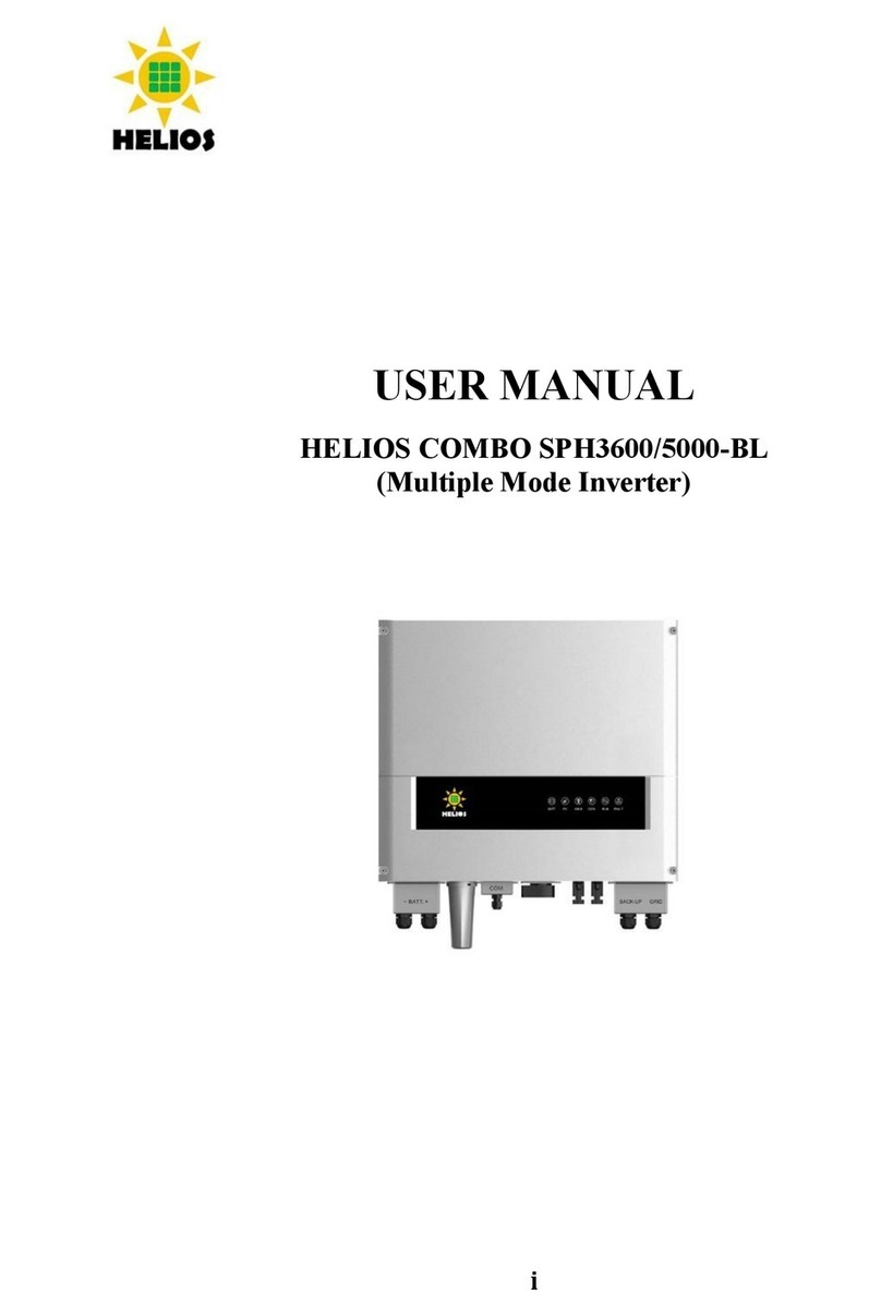
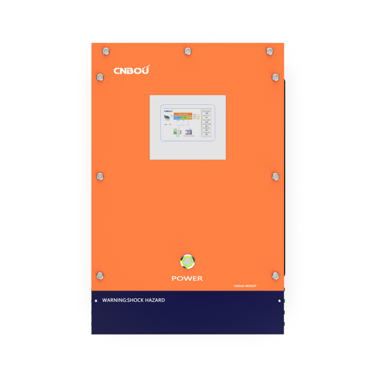
Helios RM-PSW2KVA Series User manual

1
List ofContents
1.Features
1-1Application 2
1-2Electricalperformance 3
1-3Mechanicaldrawings 4
2.Introduction
2-1Front paneloperations 5
2-2Rearpaneloperations 6
2-3Installation 8
2-4Quickhook upand testing 8
2-5AC safetygrounding 10
2-6MakingDCwiringconnections 11
2-7Inverteroperation 12
2-8Coolingfanworkingcode 14
3.Maintenance 14
4.Troubleshooting guide 14
5.Warranty 15
6.Important safetystriations
6-1Generalsafetyprecautions 16
6-2Precautionswhen working withbatteries 16
7.AppendicesA
7-1Dipswitch 17
7-2TuneVR 17

2
1.Features
nPuresine waveoutput(THD <3%)RLoad
nBypassfunction
nOutput frequency: 50/ 60Hzswitch
nRS 232 interface/ remotecontrolsport / Wireconnection toPC
nWiredRemotecontrol
nThermostaticallycontrolled coolingfan
nAdvancedmicroprocessor
nProtection :Input lowvoltage Overload Shortcircuit
LowbatteryalarmInput overvoltageovertemperature
1-1Utilities Application
1-1-1Powertools circularsaws,drills,grinders,sanders,buffers,weedand hedge
trimmers, aircompressors.
1-1-2Officeequipment computers, printers, monitors, facsimile machines,scanner.
1-1-3Householditems vacuumcleaners,fans,fluorescentandincandescentlights,
shavers, sewing machines,
1-1-4Kitchenappliances microwaveovens,refrigeratorsand freezers,coffeemakers,
blenders,icemarkers, toasters.
1-1-5Industrialequipment metalhalide lamp, high pressuresodiumlamp.
1-1-6Homeentertainmentelectronics television,VCRs,video games,stereos,musical
instruments,satelliteequipment.

3
1
-
2
Electrical Performance
Specification Model
Item
RM-PSW
122KVA
(2U)
RM-PSW
242KVA
(2U)
RM-PSW
482KVA
(2U)
RM-PSW
1102KVA
(2U)
RM-PSW
2202KVA
(2U)
RM-PSW
122KVAE
(2U)
RM-PSW
242KVAE
(2U)
RM-PSW
482KVAE
(2U)
RM-PSW
1102KVAE
(2U)
RM-PSW
2202KVAE
(2U)
ContinuousOutput
P
ower
2000W
3Min 2300W
SurgeRating
3Sec. 2500W
Peak 4000W
Input Voltage 12V 24V 48V 110V 220V 12V 24V 48V 110V 220V
Frequency 50/60Hz ±0.05%(SwitchSelectable)
PeakOutput Current 25A 11A
Efficiency(fullload) 86% 88% 90% 94% 94% 87% 90% 92% 94% 94%
NoLoad CurrentDraw
1.45A
0.7A 0.45A
0.38A
0.18A
1.47A
0.8A 0.47A
0.4A 0.2A
OutputWaveform RLoadPureSineWave<3%THD
Output Voltage
Adjustment
100~120V(Tune VR) 200~240V(TuneVR)
P.F. 1.0 1.0
InputVoltageRegulation
10-16
VDC
20-32
VDC
42-62
VDC
90-140
VDC
180-275
VDC
10-16
VDC
20-32
VDC
42-62
VDC
90-140
VDC
180-275
VDC
DCInputovervoltage
alarm 15.5VDC
31VDC
61VDC
135VDC
270VDC
15.5VDC
31VDC
61VDC
135VDC
270VDC
DCInputovervoltage
shut-down 16.0VDC
32.0VDC
62.0VDC
140VDC
275VDC
16.0VDC
32.0VDC
62.0VDC
140VDC
275VDC
DCInputundervoltage
alarm10.5VDC
21.0VDC
43.0VDC
95VDC
185VDC
10.5VDC
21.0VDC
43.0VDC
95VDC
185VDC
DCInputundervoltage
shut-down 10.0VDC
20.0VDC
42.0VDC
90VDC
180VDC
10.0VDC
20.0VDC
42.0VDC
90VDC
180VDC
Protection Overload,ShortCircuit,ReversePolarity(Fuse),Over/UnderInputVoltage, OverTemperature
DigitalDisplayOVP, UVP, OTP,OLP,VAC, AMP, WATT, VDC, TEMP, Hz
Alarm Rear Panel Alarm Relay ( NO, COM, NC ) For DC Under or Overvoltage ( rated 250vac 5A )
EMCFCC ClassA
EN55022:2006 ClassA
EN61000-3-2: 2006
EN61000-3-3: 1995+ A1:2001+A2:2005
InterfaceControlPort RS-232WithBaudRate2400, 4800, 9600, 19200 (SwitchSelectable)
RemoteControlUnit
Optional
ACInput110VAC220VAC
ACFrequency(50Hz~ 60Hz) ±3% (50Hz~ 60 Hz) ±3%
Bypass 4~6ms 4~6ms
OperatingTemperature
Range
-20to50
StorageTemperature
Range
-30to70
Dimensions 435(L) ×424(W) ×88(H)mm
Weight 12.8kgs
Note:The specificationsaresubject tochangewithout notice.
Safety EN60950-1

5
2.Introduction:
Thepowerinverterseriesarethe memberofthemostadvanced line ofmobileAC
powersystemsavailable.
Toget themost out ofthe powerinverter,it must beinstalled andusedproperly.
Pleaseread the instructionsinthismanualbeforeinstallingandusing thismodel.
2-1Front PanelOperation:
2-1-1Frontview:
2-1-2ON/ OFFswitch:
PowerON/ OFF switch, leaveintheOFFpositionduringinstallation.
2-1-3Function Key
When sequentiallypush “FunctionKey”, itwilldisplayvariousstatusonthe
function screen,SuchasVAC, Amp,watts…andsoon.
When malfunctionisoccurred,itsdisplaywillbe flashedonthescreen.
2-1-4AC outlet(Outletsocketsavailable):

6
2
-
2Rear
Panel
Operation:
2-2-1Ventilationopenings:
Donotobstruct, allowat least3inchforairflow.
2-2-2Batteryterminals:
Connectto12V/ 24V/48Vbatteryorother12V/ 24V/48VpowerSource.
+】ispositive, -】isnegative. Reversepolarityconnection will blowinternal
fuseandmaydamageinverterpermanently.
2-2-3RS-232C:
Connecttoremotecontrolunit(optionaccessory)orconnecttocomputerto
remotecontrolworkingstatus.
Alarm relay operation:
Voltage free contacts ( NO, COM, NC )
1)With normal dc supply ON and inverter output OK, and AC by pass supply available:
NC and COM is closed.
2)With normal dc supply ON and inverter output OK, and AC by pass supply not available:
NO and COM is closed.
3)Inverter shutdown due to: “OTP, OVP, UVP, OLP, short load"
NC and COM is closed.

7
WARNING!
AnydamagescausedbyusingincorrectRS232 cablewill
be outsideof ourwarrantyscope. If you arenot surewhich
oneiscorrectRS232cable, pleasepurchasethecorrect
RS232 cablefromusdirectly.
2-2-4Connectchassisground terminaltoearthortovehiclechassisusing #8AWG
wire.
WARNING!
Operation ofthe inverterwithoutaproperground
,
connection mayresult inanelectricalsafetyhazard.
WARNING!
ShockHazard.Beforeproceedingfurther,carefully check
theinverterisNOTconnected toanybatteries,
and thatall
wiring isdisconnected fromanyelectrical
sources.Donot
connecttheoutputterminalsofthe
invertertoanincoming
AC source.

8
2
-
3
Installation:
Wheretoinstall;
The powerinvertershouldbeinstalled inalocationthatmeetsthe following
requirements.
2-3-1Dry Donot allowwatertodriporsplashontheinverter.
2-3-2Cool Ambientairtemperatureshouldbebetween-20℃and 50℃,the cooler
the better.
2-3-3Safe Donot installinabatterycompartment orotherareaswhereflammable
fumesmayexist,suchasfuelstorage areasorengine compartments.
2-3-4Ventilated Allowatleastone inchofclearancearoundtheinverterforairflow.
Ensurethe ventilationopeningsonthe rearandbottomoftheunitarenot
obstructed.
2-3-5Dust-free DonotinstalltheRM-PSW2KVA/EInverterinadustyenvironments
wherearedust, wood particlesorotherfilings/shavings.The dustcan be
pulled intotheunit whenthe coolingfanisoperating.
2-3-6Closetobatteries Avoidexcessivecablelengthsbutdonotinstall the
RM-PSW2KVA/EInverterinthesamecompartmentasbatteries.
Usetherecommendedwirelengthsand sizes(seesection2-6).
Alsodonot mount the RM-PSW2KVA/EInverterwhereitwill be exposedtothe
gasesproducedbythebattery.
Thesegasesareverycorrosiveandprolonged exposurewilldamage the
RM-PSW2KVA/EInverter.
2-4Quick hooks –upandtesting:
2-4-1Unpackand inspect thepowerinverter,checktoseethat thepowerswitchinthe
OFF position.
2-4-2Connectthecablestothepowerinputterminalsonthe rearpanelofpower
inverter.
The redterminalispositive(+)andblackterminalisnegative(-).
Insertthecablesintothe terminalsand tightenrelativenuttoclampthewires
securely.
WARNING!
Youmayobserveasparkwhen you makethisconnection
sincecurrentmay
flowtochargecapacitorsinthepower
inverter.
Donotmakethisconnectioninthepresenceoff
lammable
fumes. Explosionorfiremayresult.

9
2-4-3Beforeproceedingfurther,carefullycheckthatcableyou havejustconnected
negativeterminalof invertertothenegativeoutputpowersource.
2-4-4Connectthecablefromthe negativeterminalofthe invertertothenegative
terminalof the powersource. Makeasecureconnection.
WARNING!
Youmayobserveasparkwhen you makethis connection
sincecurrentmayflowtochargecapacitorsinthe power
inverter.
Donotmakethisconnectioninthe presenceof
flammable
fumes. Explosionorfiremayresult.
2-4-5Setthe powerswitchtotheONposition;youwillhearthe “bi-bi-bi”sound. At the
sametime,the displayisshowed the word “ASIAN”fortwotimes.Afterthat,
you will hearthe continuoussound frominternalalarm.Then,the ACvoltage
showson the display. Itmeansthe devicehasdonetheoperation.
2-4-6Setthepowerswitchtothe OFFposition;thedeviceshutdowncompletely.
2-4-7 Pleaseusea powermeteraccurately measurethetrue output R.M.S.voltageof
inverter.WeuseapowermetersuchasIDRC CP-350orABM2019to
measureourproduct.
WARNING!
Makesureall the DC connectionsaretight(torqueto9-
10
ft-lbs,11.7-
13Nm).Looseconnectionswilloverheatand
couldresultinapotentialhazard.
CAUTION!
Reversepolarityconnectionwillblowafuseininverterand
maypermanently damage the inverter.
Damagecausedbyreversingpolarityconnectionisnot
coveredbyourwarranty.

10
2-5AC SafetyGrounding:
During theACwiringinstallation, AC inputand outputground wiresareconnectedto
theinverter.TheACinputground wiremustconnecttothe incoming ground from
yourAC utilitysource.
TheACoutputgroundwireshouldgo tothegrounding pointforyourloads(for
example, adistribution panelof buschassis).
2-5-1NeutralGrounding(GFCI’s):
2-5-1-1 120Vmodels: Theneutralconductorofthe ACoutputcircuitofthe
RM-PSW2KVA/EInverterisautomatically connectedtothesafety
groundduring inverteroperation.Thisconformstonationalelectrical
code requirementsthatseparatelyderivedACsources(suchasinverter
andgenerators)havetheirneutralconductorstied togroundinthe
samewaythattheneutralconductorfromtheutilityistiedtogroundat
the GFCIbreakerpanel.Formodelsconfigured withatransferrelay,
whileACutilitypowerispresenting and theYK-PSW2KVA/EInverteris
inbypassmode,this connection (neutraloftheYK-PSW2KVA/E
Inverter’sACoutputtoinputsafetyground)isnotpresentsothatthe
utilityneutralisonlyconnectedtoground atyourbreakerpanel,as
required.
2-5-1-2 230Vmodels: Thereisno connectionmadeinsidetheYK-PSW2KVA/E
Inverterfromeitherthe line orneutralconductortothe safetyground.
GroundFaultCircuitInterrupters(GFCI’S):
InstallationsinRecreationalVehicles(forNorthAmericanapprovals)willrequire
GFCIprotectionof allbranchcircuitconnectedtothe ACoutput of thehardwire
terminalequipped inverter. Inaddition,electricalcodesrequireGFCIprotectionof
certainreceptaclesinresidentialinstallations.Whilethe puresinewaveoutput of
theinverterisequivalent tothe waveformprovided byutilities, compliancewithUL
standardsrequiresustotestandrecommendspecificGFCI. Ourcompanyhas
testedthefollowingGFCI-protected 20Areceptaclesandfoundthat they
functioned properly whenconnectedtotheoutputof the inverter.
WARNING!
Donotoperatethepowerinverterwithoutconnectingitto
Ground.
Electricalshockhazardmayresult.

11
2-6. Marking DC Wiring Connections:
Follow this procedure to connect the battery cables to the DC input terminals on the
PSW2KVA/E Inverter. Your cables should be as short as possible (ideally, less than
10 feet / 3 meters) and large enough to handle the required Current in accordance
with the electrical codes or regulations applicable to your installation.
Cables that are not an adequate gauge (too narrow) or are too long will cause
decreased inverter performance such as poor surge capability and frequent low
input voltage warnings and shutdowns.
These low input voltage warnings are due to DC voltage drop across the cables
from the inverter to the batteries.
The longer and narrower these cables, the greater the voltage drop.
WARNING!
The installation of a fuse must be on positive cable.
Failure to place a fuse on “+ “cables running between the
inverter and battery may cause damage to the inverter and
will void warranty.
Increasing your DC cable size will help improve the situation.
Our company recommends the following cables for optimum inverter performance
(apply both 120V and 230V versions)
Model No
Wire AWG
Input Current
Inline Fuse
RM-PSW122KVA
#2/0
233A
250A
RM-PSW122KVAE
#2/0
230A
250A
RM-PSW242KVA
#1/0
114A
125A
RM-PSW242KVAE
#1/0
111A
125A
RM-PSW482KVA
#2
54A
70A
RM-PSW482KVAE
#2
52A
70A
RM-PSW1102KVA
#8
24A
25A
RM-PSW1102KVAE
#8
24A
25A
RMPSW2202KVA
#16
12A
15A
RM-PSW2202KVA
#16
12A
15A
Also, use only high quality copper wiring and keep cable length short from 3-6 feet.

12
2
-
7
InverterOperation:
Tooperatethepowerinverter,turniton usingthe ON/OFF switch on thefrontpanel.
ThepowerinverterisnowreadytodeliverACpowertoyourloads.
Ifyou areoperatingseveralloadsfromthepowerinverter,turnthemon separately
aftertheinverterhasbeenturnedon.
Thiswill ensurethatthepowerinverterdoesnothavetodeliverthestartingcurrents
foralltheloadsatonce.
2-7-1Controlsandindicators:
TheON / OFF switchturnsthe controlcircuit inthe powerinverteronandoff.
ThePSW2KVA/EInverteroperatesfromaninput voltage rangingfrom:
10.0to16.0VDC for12Vmodels
20.0to32.0VDC for24Vmodels
42.0to62.0VDC for48Vmodels
90.0to140.0VDC for110Vmodels
180.0to275.0VDC for220Vmodels
ThePSW2KVA/EInverterwillindicatehigh and lowDC voltageconditionsasfollows:
Model DC Input over
voltage shut-down
DC Input over
voltagealarm
DC Input under
voltagealarm
DC Input under
voltage shut-down
RM-PSW122KVA
RM-PSW122KVAE 16.0VDC 15.5VDV 10.5VDC 10.0VDC
RM-PSW242KVA
RM-PSW242KVAE 32.0VDC 31.0VDC 21.0VDC 20.0VDC
RM-PSW482KVA
RM-PSW482KVAE 62.0VDC 61.0VDC 43.0VDC 42.0VDC
RM-PSW1102KVA
RM-PSW1102KVAE 140VDC 135VDC 95VDC 90VDC
RM-PSW2202KVA
RM-PSW2202KVAE 275VDC 270VDC 185VDC 180VDC
2-7-2Output VoltageIndicator:
LEDdisplayslight onVACasshowasoutputVoltagevalue
2-7-3Output Current Indictor
LEDdisplayslight onAMPasshowasoutputcurrentvalue
2-7-4OutputWattsIndictor
LEDdisplayslight onWattsasshowasoutputWatts’svalue
2-7-5Input DC VoltageIndictor
LED displayslight onVDC asshowasinputDCvoltage value
2-7-6 TemperatureIndictor
LED displayslight onTEMPasshowasinternaloperating temperaturevalue
2-7-7Output FrequencyDC Indictor
LEDdisplayslight onHzasshowasoutputfrequencyvalue

13
Pleasehavetheaccuracyof 6functionsofdisplay, asbelow:
Function
VAC AMP WATT
VDC TEMP
Frequency
Range
100-
120
VAC
200-
240
VAC 0-20A0-2KW
10-
16
VDC
20-
32
VDC
42-
62
VDC
90-140
VDC
180-275
VDC 0-120
50Hz
60Hz
Accuracy
±1% ±1%1% ±0.5A
±3%
±2%
±2%
±2%
±2%
±2% ±1%
±0.01
±0.01
2-7-8Overvoltageprotectionindicator: (OVP)
Theovervoltageindicatorindicatesthatthepowerinverterhasshutitselfdown
becauseitsinputvoltage exceeded12V/24V/48VDC version. (Seepage12)
2-7-9Undervoltage protectionindicator: (UVP)
Theundervoltageindicatorindicatesthatthe powerinverterhasshutitself
downbecauseitsinputvoltagefellbelow12V/24V/48VDC. (Seepage12)
2-7-10 Overtempprotection indicator:(OTP)
Theovertempindicatorindicatesthatthepowerinverterhasshutitselfdown
becauseitstemphasbecomeoverheated.Thepowerinvertermayoverheat
becauseithasbeen operatedatpowerlevelsaboveitsrating,orbecauseit
hasbeen installed inalocationwhichdoesnotallowittodissipateheat
properly.Thepowerinverterwillautomaticallybackup, onceithascooled off.
2-7-11Overloadprotection indicator:(OLP)
Theoverloadindicatorindicatesthatthepowerinverterhasshutitselfdown.
Whenoutputvoltage overcontinue power, then must returntooperatemanually.

14
2-8Coolingfanworking code:
Coolingfanofinverteris throughdetectingoutputpowerand overtemperature
situationtowork.
Whenstartto turn on theinverterand output poweris under300W,the cooling fan
doesnotstartrunning.Itcomplieswithsavingenergysourcesrequirement. Until,
outputpowerisupto300W,thecooling fan will starttoworkinordertodropthe
innertemperature.
Iftheventilation opening isobstructed,theinverterwillenterovertemperature
protection mode(OTP).Thecoolingfanwill continueworking todroptheinner
temperature.When the temperaturecomesdowntonormalsituation,theinverter
willturnon automatically.
3.Maintenance:
Verylittle maintenanceisrequiredtokeepyourinverteroperatingproperly.
Youshouldcleantheexterioroftheunitperiodicallywithadryclothtoprevent
accumulationofdustanddirt.Atthe sametime,tightentheScrewson theDCinput
terminals.
4.Troubleshooting guide:
WARNING!
Donot openordisassembletheinverter.Attempting to
servicethe unit yourselfmayresult inariskofelectrical
shockorfire.
Common problems television interference:
Operationof the powerinvertercan interferewithtelevisionreceptiononsomechannels,
if thissituationoccurs, thefollowingstepsmayhelptoalleviatethe problems.
lMakesurethatthechassisground lug onthebackofthe powerinverterissolidly
connected tothe groundsystemofyourvehicle, boat orhome.
lDonotoperatehigh powerloadswiththe powerinverterwhilewatching
television.
lMakesurethattheantenna feedingyourtelevisionprovidesan adequate(“snow
free”)signaland thatyouareusinggoodqualitycablebetween the antenna and
the television.
lMovethetelevisionasfarawayfromthepowerinverteraspossible.
lKeep thecablesbetween thebatteryandthepowerinverterasshortaspossible
and twistthemtogetherabout2to3twistsperfoot.
Thisminiradiatedinterferencefromthe cables.

15
Problemand Symptoms PossibleCauseSolution
Lowoutput voltage Using averagereading
UsetrueRMSreadingmeter
(110V:95-105VAC voltmeterandcable
220V:190-210VAC)(Ref.point 2-4-7)
Load DisplayOLPflash. Overload Reduceload.
Nooutputvoltage. Low/ Highinputvoltage. Rechargebattery,
Andfault Inputvoltage. checkconnections
andcable. (Ref. point 2-7-1)
Nooutputvoltage. Thermalshutdown Improveventilation
OverTempindicator. Makesureventilation
Load less than: 1000W openingsininverter
arenotobstructed,
reduceambient
temperature.
Nooutputvoltage, Shortcircuit orwiringerror.CheckAC wiring
OverLoad indicatorforshortcircuit or
. improperpolarity(hot
andneutralreversed)
Veryhighpowerload Removeload
5. Warranty :
Wewarrantthisproductagainstdefectsinmaterialsand workmanshipforaperiodof12
monthsfromthedateof purchaseand willrepairorreplaceanydefectivepowerinverter
whendirectlyreturned(postagepaid)tous.
This warrantywill be consideredvoidiftheunithassufferedanyobviousdamageby
naturalandman-madefactorsoralterationeitherinternalorexternalanddoesnotcover
damagearisingfromimproperusesuchasplugging theunitintoanunsuitablepower
sourcesattemptstooperateproductswithexcessivepowerconsumptionrequirement,
oruseinunsuitableenvironments.
This istheonly warrantythatthecompanymakes.
Nootherwarrantiesexpressorimplyincludingwarrantiesofmerchantabilityandfitness
foraparticularpurpose.
Repairandreplacementareyoursoleremediesandthe companyshall notbeliablefor
damages,whetherdirect,incidental,specialorconsequential,eventhoughcausedby
negligenceorotherfault.

16
6.
Important Safety Instructions
6-1General SafetyPrecautions
6-1-1Donotexposethe-PSW2KAV/EInvertertorain,snow,spray,bilgeordust.
Toreduceriskofhazard,do notcoverorobstructthe ventilationopenings.Do
notinstallthe-PSW2KVA/EInverterinazero-clearancecompartment.
Overheatingmayresult.
6-1-2Toavoidariskof fireand electronicshock. Makesurethat existingwiring isin
goodelectricalcondition; and that wiresizeisnotundersized. Donotoperate
the-PSW2KVA/EInverterwithdamaged orsubstandardwiring.
6-1-3Thisequipment containscomponentswhichcanproducearcs orsparks.
Topreventfireorexplosion do not installincompartmentscontainingbatteriesor
flammable materialsorinlocationswhererequireignitionprotected equipment.
This includesanyspace containinggasoline-powered machinery,fueltanks,or
joints, fittings, orotherconnection between componentsofthefuelsystem.
6-2PrecautionsWhenWorking withBatteries
6-2-1If batteryacidcontactsskinorclothing, washimmediatelywithsoapandwater.
If acidenterseye,immediatelyfloodeyewithrunningcoldwaterforatlease
20minutesandgetmedicalattentionimmediately.
6-2-2NEVER smokeorallowasparkorflameinvicinityofbatteryorengine.
6-2-3Donotdrop ametaltoolon thebattery.Theresultingsparksorshort-circuits
onthebatteryorotherelectricalpart maycauseanexplosion.
6-2-4Removepersonalmetalitemssuchasrings,bracelets,necklaces,and watches
whenworking withalead-acidbattery.
Alead-acidbatteryproducesashort-circuitcurrenthighenoughtoweldaring
ortheliketometal, causingasevereburn.
WARNING!
Beforeyou installanduseyourinverter, betoreadand save
thesesafetyinstructions.

17
7.Appendices A
7-1. DipSwitch(attheleftsideof inverter)
S1FREQ. (Hz)
S2 S3 BAUDRATE S4POWER SAVING
ACV-ADJ
ON 60 ON ON 2400 ON DISABLE H--------L
240V200V
OFF
50 OFF ON 4800 OFF ENABLE H--------L
120V100V
---- ---- ON OFF 9600 ---- ----- ----
---- ---- OFF OFF 19200 ---- ----- ----
S1:Freq(Hz)
S2/S3:BaudRate
S4:powersavingmode –Disable/ Enable
Whenyou setup S1~S4,please resettheinverterand letupdatedatathrough CPU.
7-2TuneVR
TuneVR (VAC)outputvoltagefrom100 120VAC or200 240VAC
TheVACvaluewill graduallyincreaseif tuneVR fromrighttoleft.
www.heliosps.com
This manual suits for next models
11
Table of contents
Other Helios Inverter manuals


