Helios WHSH HE 24 V (0-10 V) L User manual
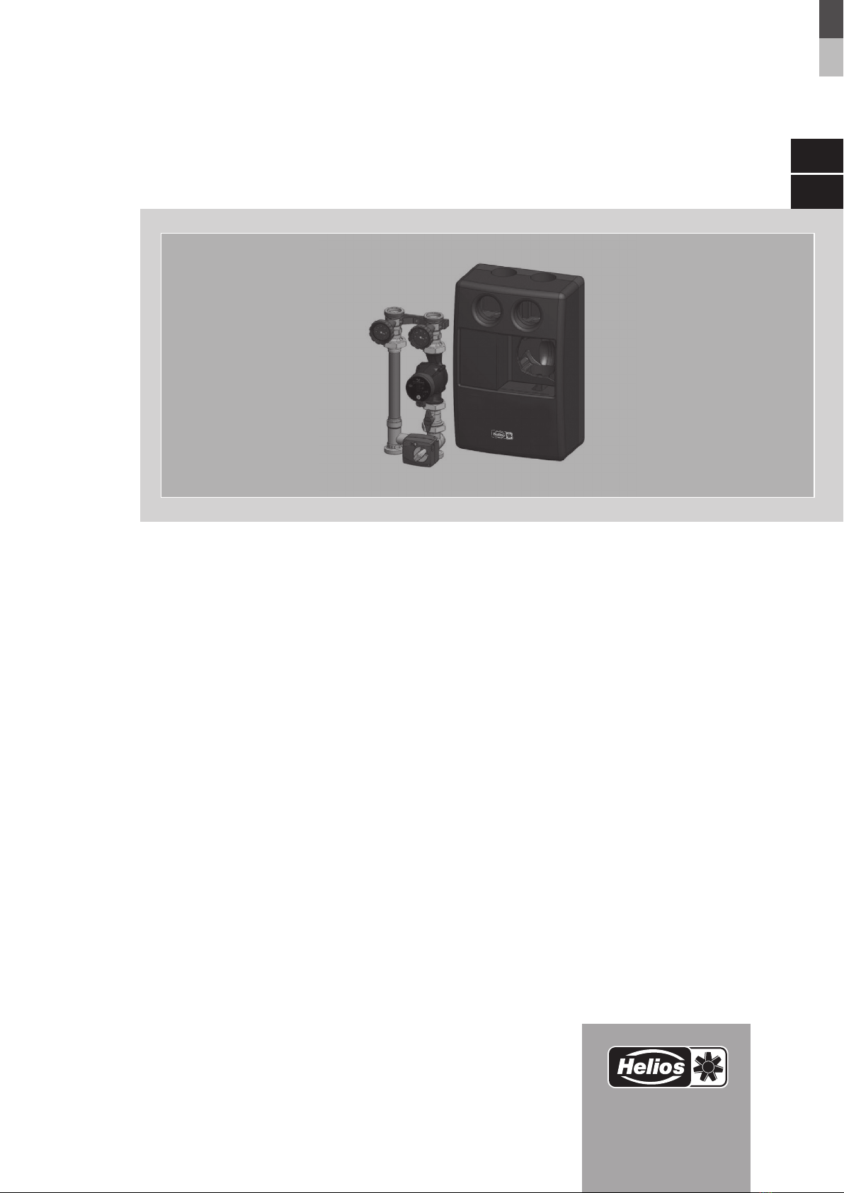
Hydraulikeinheit
WHSH HE 24 V (0-10 V) M
mit Umwälzpumpe und 3-Wege-Ventil
Helios Ventilatoren
MONTAGE- UND BETRIEBSVORSCHRIFT DE
with Circulating Pump and 3-Way Valve
Hydraulic Unit
EN
INSTALLATION AND OPERATING INSTRUCTIONS

Hydraulikeinheit WHSH HE 24 V (0-10 V) M
Montage- und Betriebsvorschrift
Inhaltsverzeichnis
KAPITEL 1 ALLGEMEINE MONTAGE- UND BETRIEBSHINWEISE .................................. Seite 1
1.0 Wichtige Informationen ..................................................................Seite 1
1.1 Warnhinweise .........................................................................Seite 1
1.2 Sicherheitshinweise.....................................................................Seite 1
1.3 Einsatzbereich.........................................................................Seite 1
1.4 Garantieansprüche – Haftungsausschluss....................................................Seite 2
1.5 Vorschriften – Richtlinien.................................................................Seite 2
1.6 Transport ............................................................................Seite 2
1.7 Sendungsannahme.....................................................................Seite 2
1.8 Einlagerung...........................................................................Seite 2
1.9 Lieferumfang..........................................................................Seite 2
KAPITEL 2 TECHNISCHE DATEN ............................................................ Seite 2
2.0 Technische Daten .....................................................................Seite 2
2.1 Materialien ...........................................................................Seite 3
2.2 Abmessungen/Anschlussmaße ............................................................Seite 3
KAPITEL 3 MONTAGE ..................................................................... Seite 3
3.0 Montage- und Installationshinweise ........................................................Seite 3
3.1 Einbau ..............................................................................Seite 4
3.2 Schwerkraftbremse.....................................................................Seite 4
3.3 Stellmotor 24 V (0-10)...................................................................Seite 5
3.4 Änderung der Durchflussrichtung ..........................................................Seite 6
3.5 Pumpengruppe gemischt ................................................................Seite 6
3.6 Wandhalterung ........................................................................Seite 7
KAPITEL 4 BETRIEB ....................................................................... Seite 7
4.0 Entlüftung der Anlage ...................................................................Seite 7
4.1 Korrekturfaktoren für Wasser-Glykol-Gemische................................................Seite 7
4.2 Wartung und Pflege ....................................................................Seite 7
4.3 Gewährleistung ........................................................................Seite 7
DEUTSCH

1
Hydraulikeinheit WHSH HE 24 V (0-10 V) M
Montage- und Betriebsvorschrift
1.0 Wichtige Informationen
Zur Sicherstellung einer einwandfreien Funktion und zur eigenen Sicherheit sind alle nachstehenden Vorschriften genau
durchzulesen und zu beachten.
Dieses Dokument ist Teil des Produktes und als solches zugänglich und dauerhaft aufzubewahren. Der Betreiber ist
für die Einhaltung aller anlagenbezogenen Sicherheitsvorschriften verantwortlich.
1.1 Warnhinweise
Nebenstehendes Symbol ist ein sicherheitstechnischer Warnhinweis. Zur Vermeidung jeglicher Gefahren-
situation, müssen alle Sicherheitsvorschriften bzw. Symbole unbedingt beachtet werden!
m GEFAHR
Warnung vor Gefahren, die bei Missachtung der Maßnahmen unmittelbar zu Tod oder schweren Verletzungen
führen.
m WARNUNG
Warnung vor Gefahren, die bei Missachtung der Maßnahmen zu Tod oder schweren Verletzungen führen können.
m VORSICHT
Warnung vor Gefahren, die bei Missachtung der Maßnahmen zu Verletzungen führen können.
ACHTUNG
Warnung vor Gefahren, die bei Missachtung der Maßnahmen zu Sachschäden führen können.
1.2 Sicherheitshinweise
lSchutzbrille
Dient zum Schutz vor Augenverletzungen.
pGehörschutz
Dient zum Schutz vor allen Arten von Lärm.
rArbeitschutzkleidung
Dient vorwiegend zum Schutz vor Erfassen durch bewegliche Teile.
Keine Ringe, Ketten oder sonstigen Schmuck tragen.
nSchutzhandschuhe
Schutzhandschuhe dienen zum Schutz der Hände vor Reibung, Abschürfungen, Einstichen
oder tieferen Verletzungen sowie vor Berührung mit heißen Oberflächen.
mSicherheitsschuhe
Sicherheitsschuhe dienen zum Schutz vor schweren herabfallenden Teilen und verhindern
Ausrutschen auf rutschigem Untergrund.
Haarnetz
Das Haarnetz dient vorwiegend zum Schutz vor Erfassen von langen Haaren durch beweg-
liche Teile.
Schutzhelm
Der Schutzhelm dient zum Schutz vor herabfallenden und umherfliegenden Teilen und
Materialien.
Für Einsatz, Anschluss und Betrieb gelten besondere Bestimmungen; bei Zweifel ist Rückfrage erforderlich.
Weitere Informationen sind den einschlägigen Normen und Gesetzestexten zu entnehmen.
– Bei allen Arbeiten an der Hydraulikeinheit bzw. Anlage sind die allgemein gültigen Arbeitsschutz- und Unfall-
verhütungsvorschriften einzuhalten!
– Alle elektrischen Arbeiten sowie die Inbetriebnahme dürfen nur von autorisiertem Elektrofachpersonal
durchgeführt werden! Installations-, Instandhaltungs- und Wartungsarbeiten dürfen nur von geeignetem
Fachpersonal durchgeführt werden!
– Vor allen Reinigungs-, Installations-, Instandhaltungs- und Wartungsarbeiten ist folgendes einzuhalten:
mDas Gerät ist allpolig vom Netz zu trennen!
mVerbrennungsgefahr! Rohrleitungen und Armaturen können durch den Betrieb heiß sein.
– Alle anlagenbezogenen Sicherheitsvorschriften sind einzuhalten! Gegebenenfalls müssen weitere länder-
spezifische Vorschriften eingehalten werden!
– Eine leichte Zugänglichkeit für Inspektions- und Reinigungsarbeiten ist zu gewährleisten!
1.3 Einsatzbereich
– Bestimmungsgemäßer Einsatz:
Die Betriebssicherheit ist nur bei bestimmungsgemäßer Verwendung der Hydraulikeinheit gewährleistet. Die
Hydraulikbaugruppe WHSH HE 24 V (0-10 V) M wird zum Betrieb eines Heizkreislaufs in Verbindung mit einem Helios
Warmwasser-Heizregister eingesetzt. Sie steuert den Durchfluss des Wassers im Heizregister. Die Vorlauftemperatur
zum Heizregister wird mit Hilfe eines 3-Wege-Ventils geregelt, das durch einen elektrischen Stellmotor 24 V (0-10V)
betrieben wird. Die Hydraulikeinheit WHSH HE 24 V (0-10 V) M ermöglicht die zeit- und platzsparende Anbindung der
KAPITEL 1
ALLGEMEINE MONTAGE-
UND BETRIEBSHINWEISE
m
m GEFAHR
m WARNUNG
m VORSICHT
ACHTUNG
DE
o

2
Hydraulikeinheit WHSH HE 24 V (0-10 V) M
Montage- und Betriebsvorschrift
Heizregister an das Heizungsnetz.
Jede darüber hinausgehende und/oder andersartige Verwendung der Hydraulikeinheit ist untersagt und gilt als nicht
bestimmungsgemäß. Zur bestimmungsgemäßen Verwendung zählt auch die korrekte Einhaltung der Einbau- und
Betriebsanleitung.
1.4 Garantieansprüche – Haftungsausschluss
Alle Ausführungen dieser Dokumentation müssen beachtet werden, sonst entfällt die Gewährleistung. Gleiches gilt
für Haftungsansprüche an Helios. Der Gebrach von Zubehörteilen, die nicht von Helios empfohlen oder angeboten
werden, ist nicht statthaft. Eventuell auftretende Schäden unterliegen nicht der Gewährleistung. Veränderungen und
Umbauten am Gerät sind nicht zulässig und führen zum Verlust der Konformität, jegliche Gewährleistung und Haftung
ist in diesem Fall ausgeschlossen. Ansprüche jeglicher Art gegen den Hersteller und/oder seine Bevollmächtigten we-
gen Schäden aus nicht bestimmungsgemäßer Verwendung können nicht anerkannt werden.
1.5 Vorschriften – Richtlinien
Bei ordnungsgemäßer Installation und bestimmungsgemäßem Betrieb entspricht das Gerät den zum Zeitpunkt seiner
Herstellung gültigen Vorschriften und EG-Richtlinien.
1.6 Transport
m Personen- und/oder Sachschaden durch unsachgemäßen Transport!
− Geeignete Transport- und Hebemittel verwenden.
− Armaturaufbauten wie Handräder oder Griffe dürfen nicht zur Aufnahme von äußeren Kräften, wie z. B. als
Anbindungspunkte für Hebezeuge usw. zweckentfremdet werden.
− Geeignete Schutzausrüstung tragen.
− Nur mit geeigneten Schutzhandschuhen anfassen. Gewinde, Bohrungen und Ecken sind scharfkantig.
Die Sendung ist werkseitig so verpackt, dass sie gegen normale Transportbelastungen geschützt ist. Führen Sie den
Transport sorgfältig durch. Es wird empfohlen die Hydraulikeinheit bis zur Montage in der Originalverpackung zu belassen.
1.7 Sendungsannahme
Die Sendung ist sofort bei Anlieferung auf Beschädigungen und Typenrichtigkeit zu prüfen. Falls Schäden vorliegen,
umgehend Schadensmeldung unter Hinzuziehung des Transportunternehmens veranlassen. Bei nicht fristgerechter
Reklamation gehen evtl. Ansprüche verloren.
1.8 Einlagerung
Bei Einlagerung über längeren Zeitraum sind zur Verhinderung schädlicher Einwirkungen folgende Maßnahmen zu
treffen: Schutz der Steuerung durch trockene, luft- und staubdichte Verpackung (Kunststoffbeutel mit Trockenmittel und
Feuchtigkeitsindikatoren). Der Lagerort muss erschütterungsfrei, wassergeschützt und frei von Temperaturschwankun-
gen sein. Bei Weiterversand (vor allem über längere Distanzen) ist zu prüfen, ob die Verpackung für Transportart und
-weg geeignet ist. Schäden, deren Ursache in unsachgemäßem Transport, Einlagerung oder Inbetriebnahme liegen,
sind nachweisbar und unterliegen nicht der Gewährleistung. Verpackungsmaterial ist umweltgerecht zu entsorgen.
1.9 Lieferumfang
Die Hydraulikbaugruppe wird vormontiert geliefert.
1 x WHSH HE 24 V (0-10V) M Art.-Nr. 06310
Die Baugruppe besteht aus:
– Umwälzpumpe,
– 3-Wege-Ventil mit Stellantrieb
– Verrohrung
– Schwerkraftbremse
– Absperrventile mit Thermometer (Vor-/Rücklauf)
– Befestigungsschrauben
– 1 x Montage- und Betriebsvorschrift
2.0 Technische Daten
Es sind die in Kapitel 1.2 aufgeführten Sicherheitshinweise zu beachten!
m Gefahr eines Sachschadens!
Es ist durch geeignete Maßnahmen (z.B. Sicherheitsventile) sicherzustellen, dass die max. Betriebsdrücke sowie die
max. und min. Betriebstemperaturen nicht überschritten bzw. unterschritten werden.
Leistungsdaten
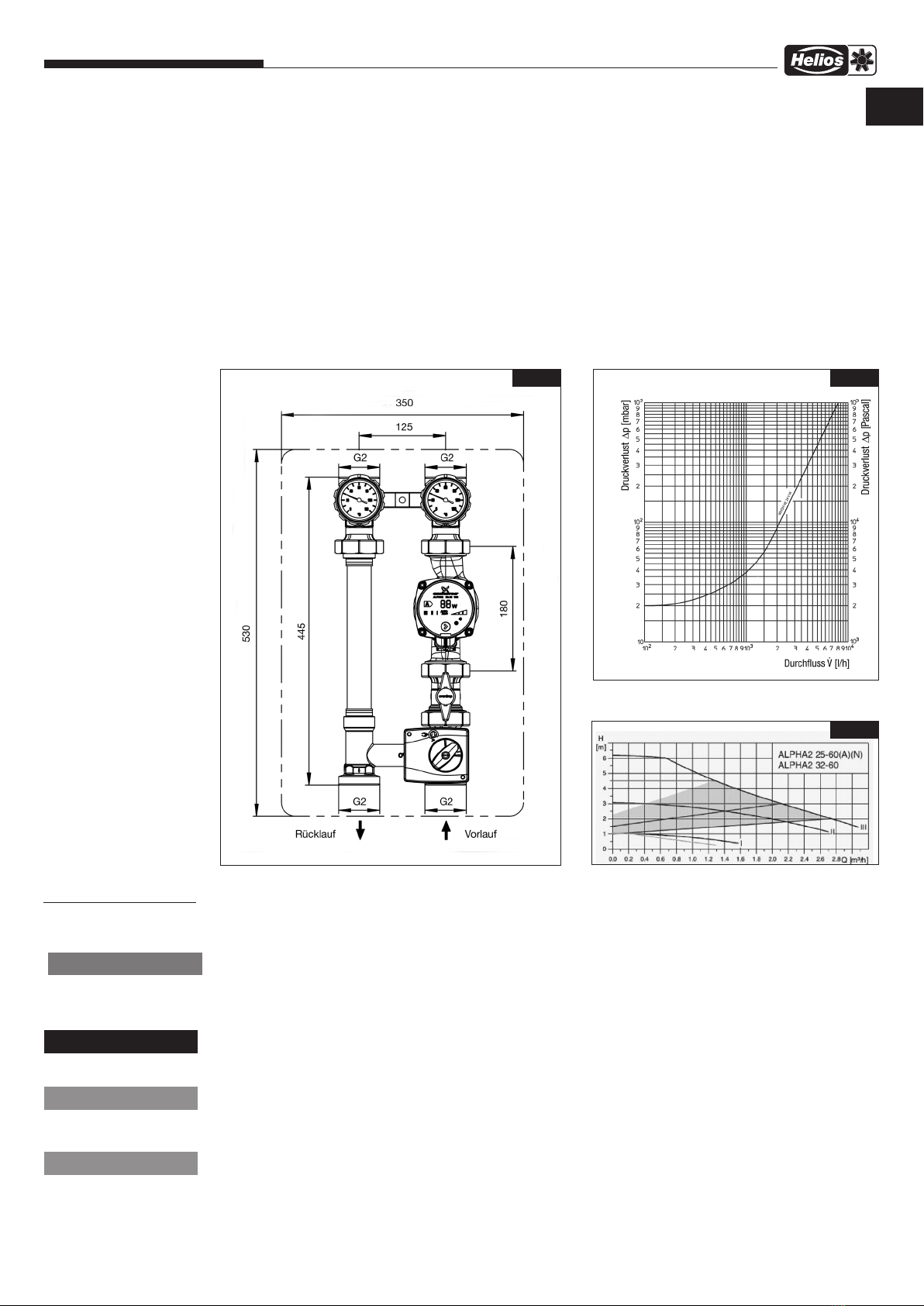
Nenngröße: DN 32
Max. Betriebsdruck: 10 bar PN10
Max. Betriebstemperatur: 95 °C
kvs-Wert: 8,1
Öffnungsdruck Sperrventil: 20 mbar
Achsabstand: 125 mm
Anschlüsse: G 2 AG, flachdichtend
Gewicht: 9,6 kg
mo
m GEFAHR
n
KAPITEL 2
TECHNISCHE DATEN
ACHTUNG
DE
3
Hydraulikeinheit WHSH HE 24 V (0-10 V) M
Montage- und Betriebsvorschrift
Medium:
Nicht aggressive Flüssigkeiten (z.B. Wasser und geeignete Wasser-Glykolgemische gemäß VDI 2035).
Nicht für Dampf, ölhaltige und aggressive Medien geeignet.
2.1 Materialien
Armaturen: Messing
Pumpe: Gehäuse aus Grauguss
Handgriffe: PA 6.6
Wandhalterung: PA 6.6
Isolierung: EPP
Flanschrohr: Kupfer
Dichtungen: EPDM
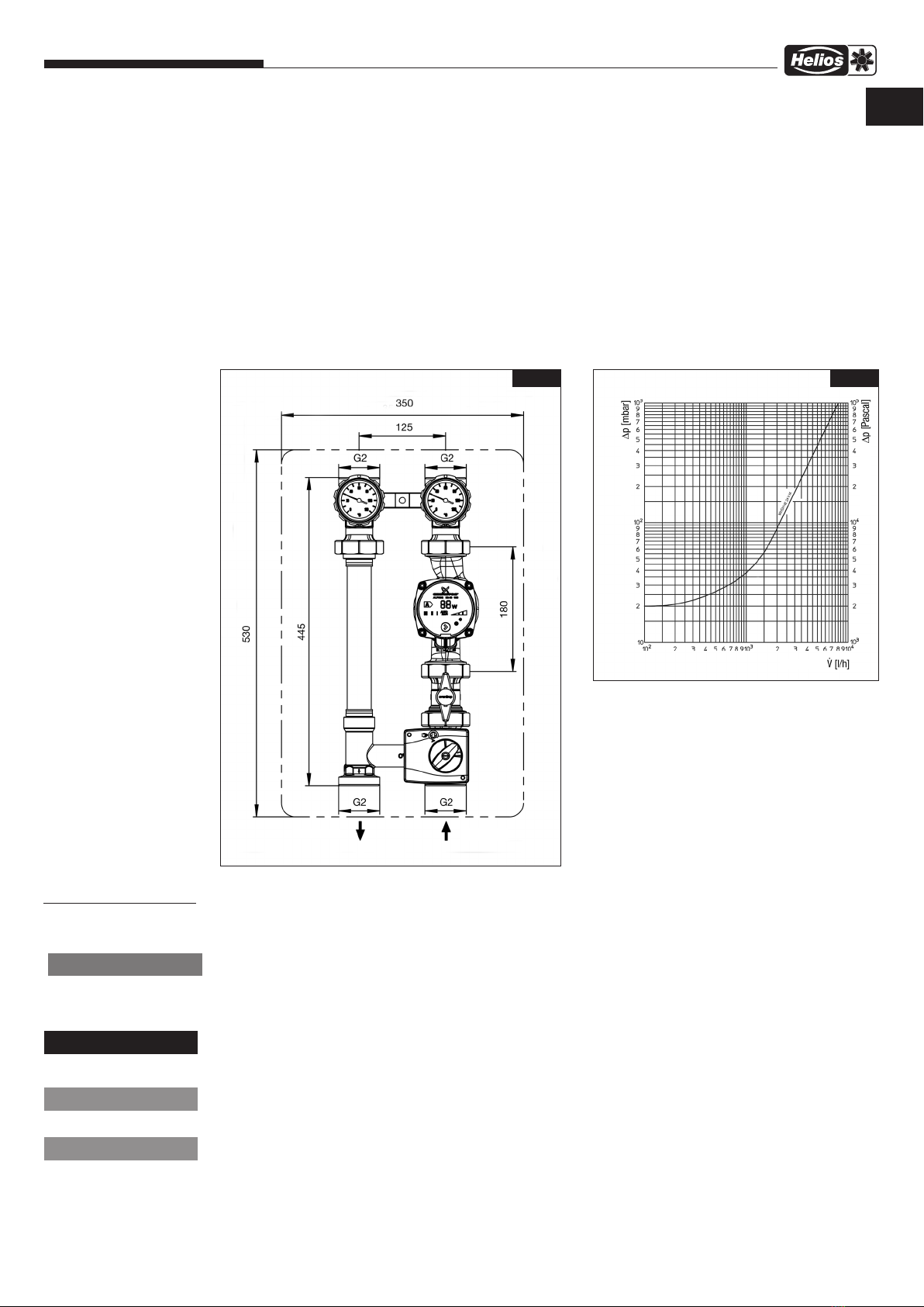
2.2 Abmessungen / Anschlussmaße
3.0 Montage- und Installationshinweise
m Verletzungsgefahr.
Vor Arbeiten an der Anlage sicherstellen, dass die Rohrleitungen und die Armaturen abgekühlt und entleert sind.
Anlage außer Betrieb nehmen.
Gewinde, Bohrungen und Ecken sind scharfkantig.
Nur mit geeigneten Schutzhandschuhen anfassen.
m Verletzungsgefahr durch Stromschlag.
Vor Öffnen bzw. Arbeiten an elektronischen Komponenten sind diese spannungsfrei zu schalten und gegen wieder-
einschalten zu sichern!
m Gefahr eines Sachschadens!
Bei der Montage dürfen keine Fette oder Öle verwendet werden.
Diese können die Dichtungen zerstören. Schmutzpartikel sowie Fett und Ölreste sind ggf. aus den Zuleitungen heraus-
zuspülen.
m Gefahr eines Sachschadens!
Max. Betriebsdrücke und max. Betriebstemperaturen nicht überschreiten.
Es ist durch geeignete Maßnahmen (z. B. Sicherheitsventile) sicherzustellen, dass die max. Betriebsdrücke
sowie die max. und min. Betriebstemperaturen nicht überschritten bzw. unterschritten werden.
Abb.1
2.4 Pumpenkennlinien
Abb.3
KAPITEL 3
MONTAGE
n
m VORSICHT
m
ACHTUNG
ACHTUNG
DE
2.3 Durchflussdiagramm
Abb.2
4
Hydraulikeinheit WHSH HE 24 V (0-10 V) M
Montage- und Betriebsvorschrift
Montage, Erstinbetriebnahme, Wartung und Reparaturen müssen von autorisierten Fachkräften (Heizungsfachbetrieb/
Vertragsinstallationsunternehmen) durchgeführt werden. (EN 5011 Teil 1 und VDE 1000 Teil 10 für Arbeiten an
elektrischen Einrichtungen)
Der Vorlauf ist werksseitig rechts angeordnet. Vor- und Rücklauf können jedoch vor Ort individuell gewechselt wer-
den.
Die Hydraulikeinheit ermöglicht das Absperren des Heizkreises. Sie verfügt über ein Absperr-Set mit in den
Handgriffen integrierten Thermometern. Die Schwerkraftbremse im Rücklaufstrang dient zur Verhinderung von
Fehlzirkulation.
Der Dreiwegemischer mit Stellmotor dient zur Vorlauftemperaturregelung und besitzt zusätzlich einen Bypass. Über
diesen Bypass wird ein Rücklaufanteil dem Vorlauf beigemischt, um die Vorlauftemperatur regeln zu können.
3.1 Einbau
Bevor die Hydraulikeinheit in die Rohrleitung eingesetzt wird, ist diese gründlich zu spülen.
Die Einbaulage ist beliebig (waagerecht, schräg oder senkrecht, in steigende oder fallende Abschnitte).
Es ist jedoch darauf zu achten, dass die Armatur immer in Pfeilrichtung durchströmt wird.
Nach der Montage sind alle Montagestellen auf Dichtheit zu überprüfen.
Die Verbindungen sind nach Einbau der Hydraulikeinheit nachzuziehen.
Installieren Sie die Pumpe immer so, dass sich die Motorwelle in horizontaler Position befindet.
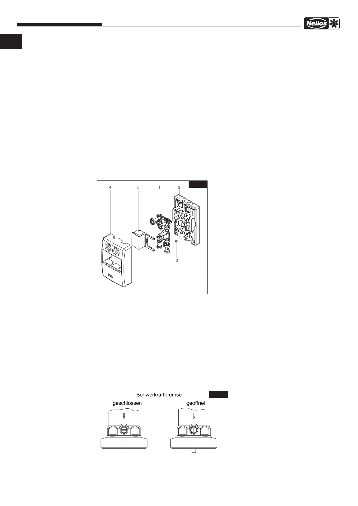
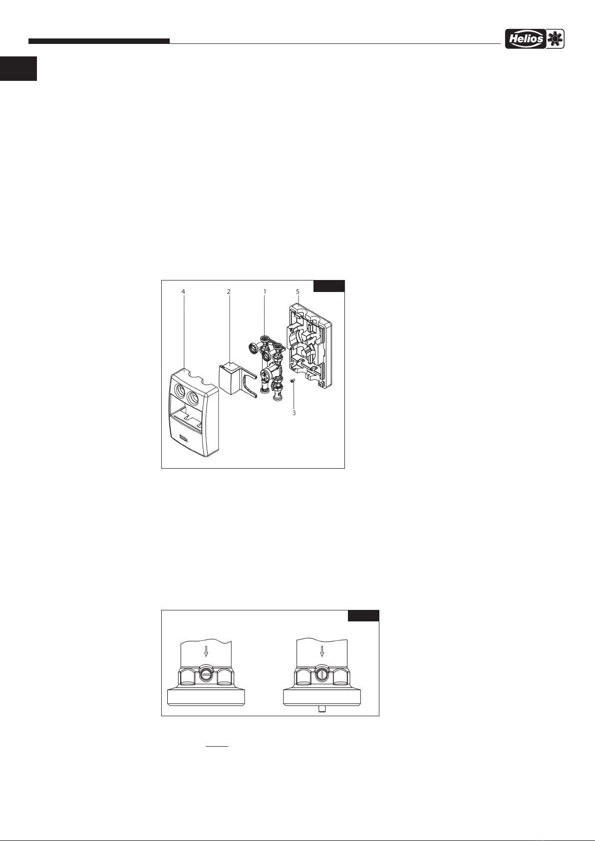
Die Station (1) aus der Isolierung nehmen. Dazu die vordere Isolierung (4) und den Einlegeblock (2) abziehen.
Die Position der Übergabestation an der Wand festlegen. Dazu die hintere Isolierung als Bohrschablone verwenden.
In die hintere Isolierung (5) das Distanzstück (3) einlegen und an die Wand mit beiliegender Schraube Ø 8x100 mit
SW12 befestigen.
Anschließend die Station (1) in die Isolierung (5) einsetzen und an die Wand mit beiliegender Schraube Ø 8x100 mit
SW12 befestigen.
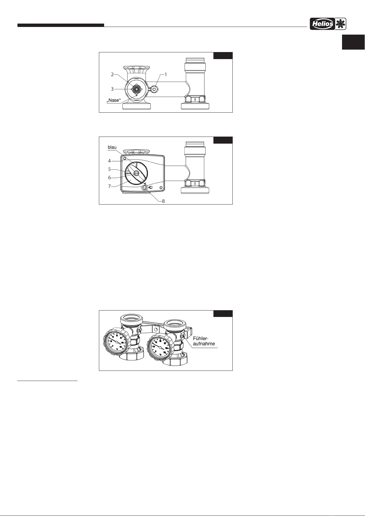
3.2 Schwerkraftbremse
BeiabgeschalteterUmwälzpumpe ist in Heizungsanlagen abhängigvomUmtriebsdruck trotz Schwerkraftbremse
eine geringe Schwerkraftzirkulation möglich.
Schwerkraftbremsen sind keine dichtschließenden Durchflussverhinderer.
Die Armaturengruppe wird vormontiert geliefert. Bei normalem Betrieb muss der Schlitz der Aufstellung
der Schwerkraftbremsen in waagerechter Stellung sein.
Betriebsstellungen (Abb.5):
Schwerkraftbremse geschlossen > Betriebsstellung
Durchfluss nur in Förderrichtung möglich.
Abb.4
Abb.5
DE

5
Hydraulikeinheit WHSH HE 24 V (0-10 V) M
Montage- und Betriebsvorschrift
Schwerkraftbremse geöffnet > Füllen, Spülen, Entlüften
Durchfluss in beide Richtungen möglich.
Bei Inbetriebnahme bzw. Wartungsarbeiten (Füllen und Spülen) muss die Schwerkraftbremse geöffnet sein.
Im Heizbetrieb muss diese wieder in die Betriebsstellung gebracht werden.
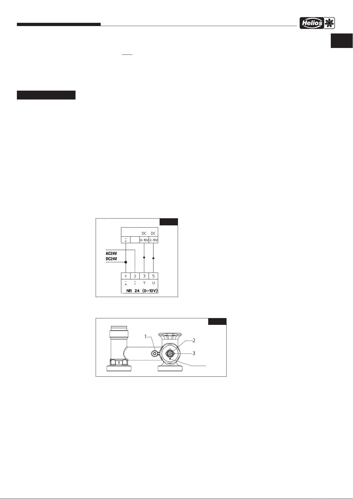
3.3 Stellmotor 24 V (0-10 V)
m Lebensgefahr durch elektrischen Stromschlag!
Bei Anschlussarbeiten an einem Regler, der unter Spannung steht, besteht die Gefahr eines tödlichen Stromschlags.
Der Stellmotor NR 24 des Dreiwegemischers kann durch Regelungen mittels 24 V (0-10) Ausgang angesteuert werden.
Anschluss an Regelung gemäß MBV Lüftungsgerät.
Der Drehwinkel ist auf 90° begrenzt. Bei Erreichen der Endanschläge wird der Stellmotor elektrisch abgeschaltet und
ist stromlos. Bei Störungen des Regelsystems kann der Antrieb durch ein zusätzlichen Drehknopf auf Handbetrieb
umgestellt werden.
3.3.1 Technische Daten
Betriebsspannung: NR 24: 24V 50Hz/60Hz (Schutzkleinspannung)
Stellsignal Y: DC 0…10 V @ 100 kΩ Eingangswiderstand
Arbeitsbereich: DC 2…10 V für 0…100% <) (0…90°)
Messspannung U: DC 2…10 V (max. 1 mA) für 0…100% <) (0…90°)
Schutzklasse: III
Drehmoment: 5 Nm
Laufzeit: 140s
Handverstellung: mechanische Getriebeausrastung
Umgebungstemperatur: 0°C - +50°C
Anschlusskabellänge: 2.2 m
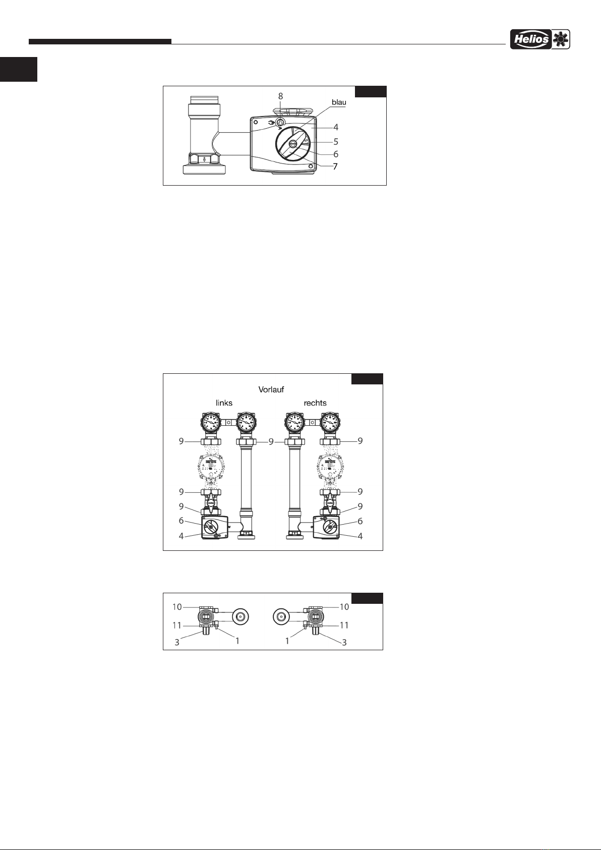
3.3.2 Montage des Stellmotors
− Verdrehsicherung (1) fest am Mischergehäuse montiert.
− Adapter (2) bis zum Anschlag auf das Mischerküken (3) stecken. Abflachung beachten!
− Mischerküken so einstellen, dass die Nase des Adapters nach unten zeigt. Das Mischerküken verschließt in dieser
Stellung Abgang nach unten (voller Bypassbetrieb, kalt).
m GEFAHR
Abb.6
Lüftungsgerät
Abb.7
DE
6
Hydraulikeinheit WHSH HE 24 V (0-10 V) M
Montage- und Betriebsvorschrift
DE
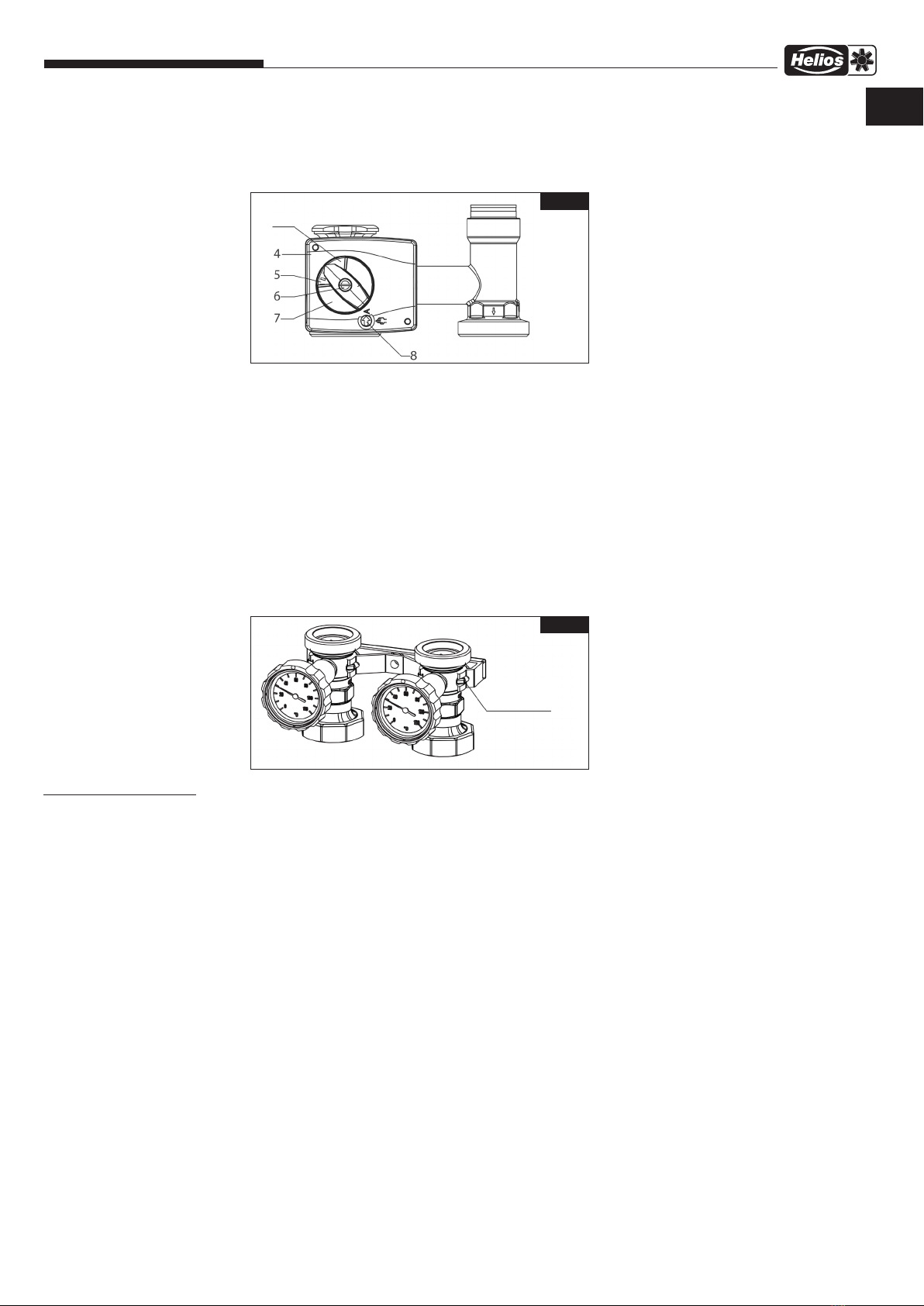
− Betriebsschalter (8) auf Handbetrieb stellen.
− Drehrichtungsanzeige (5) gemäß Abbildung auf
den Stellmotor (4) legen.
− Handverstellgriff (7) auf die Mischerachse stecken.
Der Handverstellgriff lässt sich nur in einer Rasterstellung leicht aufdrücken. Keine Gewalt anwenden!
Handverstellgriff im Uhrzeigersinn bis zum Anschlag drehen. Pfeilmarke des Handverstellgriffes befindet sich im blauen
Bereich.
− Stellmotor auf die Mischerachse setzen.
− Schraube (6) mit Fächerscheibe einstecken und die Schraube mit einem Drehmoment von > 5 Nm anziehen.
− Betriebsschalter wieder auf Automatikbetrieb stellen.
3.4 Änderung der Durchflussrichtung
Die Baugruppen sind ab Werk auf Dichtheit geprüft.
Bei Änderung der Durchflussrichtung auf Unversehrtheit der Dichtungen achten und nach dem Umbau auf Dichtheit
prüfen.
3.5 Pumpengruppe gemischt
− Verbindung (9) und Schraube (6) lösen.
− Stellmotor (4) abnehmen.
− Deckel (10) und (11) mit Schlüssel SW46 lösen.
− Mischerküken (3) auf die andere Seite montieren.
− Deckel wieder festschrauben und mit einem Drehmoment von 45 Nm anziehen.
− Verdrehsicherung (1) auf die andere Seite montieren.
Abb.9
Abb.10
Abb.11
Abb.8
7
Hydraulikeinheit WHSH HE 24 V (0-10 V) M
Montage- und Betriebsvorschrift
− Mischerküken (3) so einstellen, dass die Nase des Adapters (2) nach unten zeigt. Das Mischerküken verschließt in
dieser Stellung den Abgang nach unten (voller Bypassbetrieb, kalt).
− Betriebsschalter (8) auf Handbetrieb stellen.
− Drehrichtungsanzeige (5) gemäß Abbildung auf den Stellmotor (4) legen.
− Handverstellgriff (7) auf die Mischerachse stecken.
Der Handverstellgriff lässt sich nur in einer Rasterstellung leicht aufdrücken. Keine Gewalt anwenden!
Handverstellgriff im Uhrzeigersinn bis zum Anschlag drehen. Pfeilmarke des Handverstellgriffes
befindet sich im blauen Bereich.
− Stellmotor auf die Mischerachse setzen.
− Schraube (6) mit Fächerscheibe einstecken und die Schraube mit einem Drehmoment von > 5 Nm anziehen.
− Betriebsschalter wieder auf Automatikbetrieb stellen.
3.6 Wandhalterung
Die Wandhalterung hat integrierte Aufnahmen für ein Temperaturfühler. Zur Erfassung der Vorlauftemperatur kann ein
Temperaturfühler zwischen der EPP-Unterschale und dem Kugelhahn angebracht werden.
4.0 Entlüftung der Anlage
Vor der Inbetriebnahme muss die Anlage aufgefüllt und entlüftet werden. Dabei sind die zulässigen Betriebsdrücke zu
berücksichtigen.
4.1 Korrekturfaktoren für Wasser-Glykol-Gemische
Die Korrekturfaktoren der Frostschutzmittelhersteller müssen bei der Durchflusseinstellung berücksichtigt
werden.
4.2 Wartung und Pflege
Die Armatur ist wartungsfrei.
4.3 Gewährleistung
Es gelten die zum Zeitpunkt der Lieferung gültigen Gewährleistungsbedingungen von Helios.
Abb.12
Abb.13
KAPITEL 4
BETRIEB
DE
− Betriebsschalter (8) auf Handbetrieb stellen.
− Drehrichtungsanzeige (5) gemäß Abbildung auf
den Stellmotor (4) legen.
− Handverstellgriff (7) auf die Mischerachse stecken.
Der Handverstellgriff lässt sich nur in einer Rasterstellung leicht aufdrücken. Keine Gewalt anwenden!
Handverstellgriff im Uhrzeigersinn bis zum Anschlag drehen. Pfeilmarke des Handverstellgriffes befindet sich im blauen
Bereich.
− Stellmotor auf die Mischerachse setzen.
− Schraube (6) mit Fächerscheibe einstecken und die Schraube mit einem Drehmoment von > 5 Nm anziehen.
− Betriebsschalter wieder auf Automatikbetrieb stellen.
3.4 Änderung der Durchflussrichtung
Die Baugruppen sind ab Werk auf Dichtheit geprüft.
Bei Änderung der Durchflussrichtung auf Unversehrtheit der Dichtungen achten und nach dem Umbau auf Dichtheit
prüfen.
3.5 Pumpengruppe gemischt
− Verbindung (9) und Schraube (6) lösen.
− Stellmotor (4) abnehmen.
− Deckel (10) und (11) mit Schlüssel SW46 lösen.
− Mischerküken (3) auf die andere Seite montieren.
− Deckel wieder festschrauben und mit einem Drehmoment von 45 Nm anziehen.
− Verdrehsicherung (1) auf die andere Seite montieren.
Abb.9
Abb.10
Abb.11

Hydraulic Unit WHSH HE 24 V (0-10 V) M
Installation and Operating Instructions
Table of Contents
CHAPTER 1 GENERAL INSTALLATION AND OPERATING INSTRUCTIONS .......................... Page 1
1.0 Important information ...................................................................Page 1
1.1 Warning instructions ....................................................................Page 1
1.2 Safety instructions......................................................................Page 1
1.3 Area of application .....................................................................Page 1
1.4 Warranty claims – Exclusion of liability ......................................................Page 2
1.5 Regulations - Guidelines .................................................................Page 2
1.6 Shipping .............................................................................Page 2
1.7 Receipt ..............................................................................Page 2
1.8 Storage..............................................................................Page 2
1.9 Scope of delivery ......................................................................Page 2
CHAPTER 2 TECHNICAL DATA.............................................................. Page 2
2.0 Technical data ........................................................................Page 2
2.1 Materials ............................................................................Page 3
2.2 Dimensions/connection dimensions ........................................................Page 3
CHAPTER 3 ASSEMBLY.................................................................... Page 3
3.0 Assembly and installation instructions ......................................................Page 3
3.1 Installation............................................................................Page 4
3.2 Check valve ..........................................................................Page 4
3.3 Actuator 24 V (0-10) ....................................................................Page 5
3.4 Change of flow direction .................................................................Page 6
3.5 Pump assembly mixed ..................................................................Page 6
3.6 Wall bracket ..........................................................................Page 7
CHAPTER 4 OPERATION ................................................................... Page 7
4.0 System ventilation......................................................................Page 7
4.1 Correction factors for water glycol mixtures ..................................................Page 7
4.2 Maintenance and care ..................................................................Page 7
4.3 Warranty .............................................................................Page 7
ENGLISH

1
Hydraulic Unit WHSH HE 24 V (0-10 V) M
Installation and Operating Instructions
1.0 Important information
In order to ensure complete and effective operation and for your own safety, all of the following instructions should be
read carefully and observed.
This document forms part of the product and as such should be permanently stored so that it is accessible in order to
ensure the safe operation of the assembly. All plant-related safety regulations must be observed.
1.1 Warning instructions
The adjacent symbol is a safety-relevant warning symbol. All safety regulations and/or symbols must be ab-
solutely adhered to, so that any dangerous situation is avoided!
m DANGER
Indicates dangers which will directly result in death or serious injury if the safety instruction is not followed.
m WARNING
Indicates dangers which will result in death or serious injury if the safety instruction is not followed.
m CAUTION
Indicates dangers which can result in injuries if the safety instruction is not followed.
ATTENTION
Indicates dangers which can result in material damage if the safety instruction is not followed.
1.2 Safety instructions
lProtective glasses
Serves to protect against eye injuries.
pEar protectors
Serves to protect against all kinds of noise.
rProtective clothing
Primarily serves to protect against contact with moving parts.
Do not wear rings, chains or other jewellery.
nProtective gloves
Protective gloves serve to protect the hands against rubbing, abrasions, cuts or more pro-
found injuries, as well as contact with hot surfaces.
mProtective footwear
Protective footwear serves to protect against heavy falling parts and from slipping on slip-
pery surfaces.
Hair net
The hair net primarily serves to protect long hair against contact with moving parts.
Safety helmet
The safety helmet serves to protect against falling and flying parts and materials.
Special regulations apply for use, connection and operation; consultation is required in case of doubt. Further
information can be found in the relevant standards and legal texts.
– With regard to all work on the hydraulic unit or system, the generally applicable safety at work and accident
prevention regulations must be observed!
– All electrical work and the commissioning must only be carried out by authorised, qualified electricians!
Installation, servicing and maintenance work must only be carried out by suitable specialist personnel!
– The following must be observed before all cleaning, installation, servicing and maintenance work:
mThe unit must be completely (all poles) disconnected from the mains power supply!
mDanger of burns! Pipes and fittings may become hot during operation.
– All plant-related safety regulations must be observed! If applicable, further country-specific regulations must
also be observed!
– Easy accessibility for inspection and cleaning work must be ensured!
1.3 Area of application
– Intended use:
Operational reliability is only ensured when the hydraulic unit is used as intended. The hydraulic assembly WHSH HE 24
V (0-10 V) M is used to operate a heating circuit in connection with a Helios hot water heating register. It controls the
water flow in the heating register. The flow temperature to the heating register is controlled with a 3-way valve, which
is operated by an electric actuator 24 V (0-10V). The hydraulic unit WHSH HE 24 V (0-10 V) M enables the time and
space-saving connection of the heating register to the heating network.
All additional and/or other uses of the hydraulic unit are prohibited and considered improper. Intended use also includes
CHAPTER 1
GENERAL INSTALLATION
AND OPERATING
INSTRUCTIONS
m
m DANGER
m WARNING
m CAUTION
ATTENTION
EN
o

2
Hydraulic Unit WHSH HE 24 V (0-10 V) M
Installation and Operating Instructions
full compliance with the installation and operating instructions.
1.4 Warranty claims – Exclusion of liability
All versions of this documentation must be observed, otherwise the warranty shall cease to apply. The same applies
to liability claims against Helios. The use of accessory parts, which are not recommended or offered by Helios, is not
permitted. Any possible damages are not covered by the warranty. Changes and modifications to the unit are not per-
mitted and lead to a loss of conformity, and any warranty and liability shall be excluded in this case. Claims of any kind
against the manufacturer and/or its representatives due to damage caused by improper use cannot be acknowledged.
1.5 Regulations - Guidelines
If the product is installed correctly and used to its intended purpose, it conforms to all applicable regulations and EC
directives at its date of manufacture.
1.6 Shipping
m Personal injury and/or material damage due to incorrect shipping!
− Use suitable means of transportation and lifting.
− Fittings such as handwheels or handles must not be used for absorbing external forces, e.g. misused as attach-
ment points for lifting devices etc.
− Wear suitable protective clothing.
− Only touch with suitable protective gloves. Threads, bores and corners have sharp edges.
The unit is packed ex works in such a way that it is protected against normal transport strain. Carry out the shipping
carefully. It is recommended to leave the hydraulic unit in the original packaging until assembly.
1.7 Receipt
The shipment must be checked for damage and correctness immediately upon delivery. If there is any damage,
promptly report the damage with the assistance of the transport company. If complaints are not made within the agreed
period, any claims could be lost.
1.8 Storage
When storing for a prolonged time, the following steps are to be taken to avoid damaging influences: Control system
protection by dry, airtight and dust-proof packaging (plastic bag with desiccant and humidity indicators). The storage
site must be vibration-free, water-tight and free of temperature variations. When transhipping (especially over longer
distances) check if the packing is adequate for method and manner of transportation. Damages due to improper
transportation, storage or commissioning are not liable for warranty. Packaging material must be disposed of in an
environmentally friendly manner.
1.9 Scope of delivery
The hydraulic assembly is supplied pre-assembled.
1 x WHSH HE 24 V (0-10V) M Ref. no. 06310
The assembly consists of:
– circulating pump,
– 3-way valve with actuator
– piping,
– check valve
– shut-off valve with thermometer (flow/return)
– fixing screws
– 1 x installation and operating instructions
2.0 Technical data
The safety instructions specified in section 1.2 must be observed!
m Risk of material damage!
Appropriate measures (e.g. safety valves) must be taken to ensure that the max. operating pressures and the max.
and min. operating temperature limits are not breached.
Performance data
Nominal size: DN 32
Max. operating pressure: 10 bar PN10
Max. operating temperature: 95 °C
kvs value: 8.1
Opening pressure check valve: 20 mbar
Centre distance: 125 mm
Connections: G 2 AG, flat-sealing
Weight: 9,6 kg
mo
m DANGER
n
CHAPTER 2
TECHNICAL DATA
ATTENTION
EN
3
Hydraulic Unit WHSH HE 24 V (0-10 V) M
Installation and Operating Instructions
Medium:
Non-aggressive liquids (e.g. water and appropriate water glycol mixtures according to VDI 2035).
Not suitable for steam, oily and aggressive media.
2.1 Materials
Fittings: Brass
Pump: Grey cast iron casing
Handles: PA 6.6
Wall bracket: PA 6.6
Insulation: EPP
Flange pipe: Copper
Seals: EPDM
2.2 Dimensions / connection dimensions
3.0 Assembly and installation instructions
m Risk of injury.
Ensure that the pipes and fittings are cool and empty before working on the system.
Decommission the system.
Threads, bores and corners have sharp edges.
Only touch with suitable protective gloves.
m Risk of injury due to electric shock.
Make sure components are isolated from the power supply and protected against reactivation before opening and
working on electronic components!
m Risk of material damage!
Fats or oils must not be used during installation.
These can destroy seals. Particles of dirt as well as fat and oil residues must be rinsed out of the supply lines.
m Risk of material damage!
Do not exceed max. operating pressures and max. operating temperatures.
Appropriate measures (e.g. safety valves) must be taken to ensure that the max. operating pressures and the max. and
min. operating temperature limits are not breached.
Fig.1
CHAPTER 3
ASSEMBLY
n
m CAUTION
m
ATTENTION
ATTENTION
EN
2.3 Flow rate diagram
Fig.2
Pressure loss
Pressure loss
Flow
Flow
Return
4
Hydraulic Unit WHSH HE 24 V (0-10 V) M
Installation and Operating Instructions
Assembly, initial commissioning, maintenance and repairs must be carried out by authorised specialists (heating
contractor/contract installation company). (EN 5011 part 1 and VDE 1000 part 10 for work on electrical installations)
The flow is on the right side as a standard factory setting. However, the flow and return can be switched individually
on site.
The hydraulic unit allows the heating circuit to be blocked off. It has a block-off set with thermometers integrated in
the handles. The check valve in the return line serves to prevent unwanted circulation.
The three-way mixer with actuator is used to control the flow temperature and it also has a bypass. A portion of the
return is added to the flow via this bypass in order to control the flow temperature.
3.1 Installation
The hydraulic unit must be thoroughly rinsed before it is placed in the piping.
The unit can be mounted in any position (horizontal, diagonal or vertical, in rising or falling sections).
However, it must be ensured that the air always flows through the valve in the direction of the arrow.
All installation locations must be checked for tightness after installation.
The connections must be retightened after installation of the hydraulic unit.
Always install the pump so that the motor shaft is in the horizontal position.
Remove the station (1) from the insulation. Remove the front insulation (4) and the insert block (2) for this purpose.
Determine the position of the connection point on the wall. Use the rear insulation as a drill template here.
Insert the spacer (3) in the rear insulation (5) and mount to the wall with the enclosed screw Ø 8x100 with SW12.
Then place the station (1) in the insulation (5) and mount to the wall with the enclosed screw Ø 8x100 with SW12.
3.2 Check valve
Depending on the operating pressure, low gravity circulation is possible in heating systems despite the check
valve when the circulating pump is deactivated.
Check valves are not tight-closing flow inhibitors.
The fitting group is supplied preassembled. In case of normal operation, the positioning slot of the check valves must
be in the horizontal position.
Operating positions (Fig.5):
Check valve closed > Operating position
Flow only possible in the conveying direction.
Fig.4
Fig.5
EN
Closed Open
Check valve
5
Hydraulic Unit WHSH HE 24 V (0-10 V) M
Installation and Operating Instructions
Check valve open > Filling, flushing, venting
Flow possible in both directions.
With regard to commissioning or maintenance work (filling and rinsing), the check valve must be open.
This must be returned to the operating position during heating operation.
3.3 Actuator 24 V (0-10 V)
m Danger to life due to electric shock!
With regard to connection work on a live controller, there is a risk of fatal electric shock.
The actuator NR 24 of the three-way mixer can be controlled by control units using the 24 V (0-10) output. Connection
to control unit pursuant to ventilation unit installation and operating instructions.
The rotation angle is limited to 90°. When the limit stops are reached, the actuator will be switched off electrically and
currentless. In case of control system errors, the actuator can be switched to manual operation by means of an ad-
ditional rotary switch.
3.3.1 Technical data
Operating voltage: NR 24: 24V 50Hz/60Hz (safety extra-low voltage)
Control signal Y: DC 0…10 V @ 100 kΩ input resistance
Working range: DC 2…10 V for 0…100% <) (0…90°)
Measuring voltage U: DC 2…10 V (max. 1 mA) for 0…100% <) (0…90°)
Protection class: III
Torque: 5 Nm
Runtime: 140s
Manual adjustment: mechanical gear disengagement
Ambient temperature: 0°C - +50°C
Connection cable length: 2.2 m
3.3.2 Assembly of actuator
− Rotation lock (1) fixed to mixer housing.
− Insert adapter (2) as far as possible in the mixer plug (3). Note flattening!
− Set mixer plug so that the nose of the adapter points down. In this position, the mixer plug closes the outlet
downwards (full bypass operation, cold).
m DANGER
Fig.6
Ventilation unit
Fig.7
EN
Red
Black
White White
“Nose”

6
Hydraulic Unit WHSH HE 24 V (0-10 V) M
Installation and Operating Instructions
EN
− Set operating switch (8) to manual operation.
− Place rotation direction indicator (5) on actuator (4)
pursuant to illustration.
− Place adjustment handle (7) on the mixer axle.
The adjustment handle should only be pressed lightly into a locked position. Do not use force!
Turn the adjustment handle clockwise up to the stop. The arrow for the adjustment handle is located in the blue area.
− Place actuator on the mixer axle.
− Insert screw (6) with serrated washer and tighten the screw with a tightening torque > 5 Nm.
− Set operating switch back to automatic operation.
3.4 Change of flow direction
The assemblies are checked for tightness ex works.
In case of a change of flow direction, pay attention to the integrity of the seals and check for tightness after the con-
version.
3.5 Pump assembly mixed
− Loosen connection (9) and screw (6).
− Remove actuator (4).
− Loosen cover (10) and (11) with key SW46.
− Mount mixer plug (3) on the other side.
− Screw cover back on and tighten with a tightening torque 45 Nm.
− Mount rotation lock (1) on the other side.
Fig.9
Fig.10
Fig.8
Blue
Left Right
Flow
7
Hydraulic Unit WHSH HE 24 V (0-10 V) M
Installation and Operating Instructions
− Set mixer plug (3) so that the nose of the adapter (2) points down. In this position, the mixer plug closes the outlet
downwards (full bypass operation, cold)
− Set operating switch (8) to manual operation.
− Place rotation direction indicator (5) on actuator (4) pursuant to illustration.
− Place adjustment handle (7) on the mixer axle.
The adjustment handle should only be pressed lightly into a locked position. Do not use force!
Turn the adjustment handle clockwise up to the stop. The arrow for the adjustment handle is located in the blue area.
− Place actuator on the mixer axle.
− Insert screw (6) with serrated washer and tighten the screw with a tightening torque > 5 Nm.
− Set operating switch back to automatic operation.
3.6 Wall bracket
The wall bracket has integrated mounts for a temperature sensor. In order to measure the flow temperature, a tempe-
rature sensor can be placed between the EPP subshell and the ball valve.
4.0 System ventilation
The system must be filled and ventilated before commissioning. In this respect, the permissible operating pressures
must be taken into account.
4.1 Correction factors for water glycol mixtures
The correction factors of the antifreeze agent manufacturer must be taken into account for the flow setting.
4.2 Maintenance and care
The fitting is maintenance-free.
4.3 Warranty
The applicable Helios warranty conditions at the time of delivery shall apply.
Fig.12
Fig.13
CHAPTER 4
OPERATION
EN
Blue
Sensor
mount

8
Hydraulic Unit WHSH HE 24 V (0-10 V) M
Installation and Operating Instructions

9
Hydraulic Unit WHSH HE 24 V (0-10 V) M
Installation and Operating Instructions

Als Referenz am Gerät griffbereit aufbewahren! Druckschrift-Nr.
Please keep this manual for reference with the unit! Print-No.:
Conservez cette notice à proximité de l’apapreil! N° Réf. 29 647-001/18-0292/V01/0819
Service und Information
DHELIOS Ventilatoren GmbH + Co KG · Lupfenstraße 8 · 78056 VS-Schwenningen FHELIOS Ventilateurs · Le Carré des Aviateurs · 157 av. Charles Floquet · 93155 Le Blanc Mesnil Cedex
CH HELIOS Ventilatoren AG · Tannstraße 4 · 8112 Otelfingen GB HELIOS Ventilation Systems Ltd. · 5 Crown Gate · Wyncolls Road · Severalls Industrial Park ·
AHELIOS Ventilatoren · Postfach 854 · Siemensstraße 15 · 6023 Innsbruck Colchester · Essex · CO4 9HZ
www.heliosventilatoren.de
Other manuals for WHSH HE 24 V (0-10 V) L
1
Table of contents
Languages:
Other Helios Measuring Instrument manuals


Popular Measuring Instrument manuals by other brands

Anritsu
Anritsu MP1632C Operation manual

Svantek
Svantek SV 271 LITE user manual

Hanna Instruments
Hanna Instruments HI97709 instruction manual

Bacharach
Bacharach 3015-4286 Installation & operating instructions

Keithley
Keithley System SourceMeter 2601B quick start guide

Lutron Electronics
Lutron Electronics HT-315 manual


