Helios PD2-6400 User manual

Helios PD2-6400 High Voltage & High Current Meter
Instruction Manual
PRECISION DIGITAL CORPORATION
233 South Street • Hopkinton MA 01748 USA
Tel (800) 343-1001 • Fax (508) 655-8990
www.predig.com
•Large Display NEMA 4X, IP65 Wall Mounted Meter
•(1) High Voltage and (1) High Current Input
•Multiplication for Apparent Power Calculation
•0-300 VAC or VDC Voltage Input
•0-5 AAC or ADC Current Input
•Large Dual-Line 6-Digit Display, 1.8" (46 mm) Digits Readable up to 100 Feet (30 Meters) Away
•4 Relays with Interlocking Capability + Isolated 4-20 mA Output Option
•Free PC-Based, On-Board, MeterView Pro USB Programming Software
•SunBright Display Standard Feature; Great for Outdoor Applications
•Operating Temperature Range: -40 to 65°C (-40 to 149°F)
•Conformal Coated PCBs for Dust and Humidity Protection
•UL & C-UL Listed. E160849; 508 Industrial Control Equipment
•Input Power Options: 85-265 VAC / 90-265 VDC or 12-24 VDC / 12-24 VAC
•Programmable Display, Function Keys & Digital Inputs
•On-Board RS-485 Serial Communications
•Modbus RTU Communication Protocol Standard
•External 4-Relay & Dual 4-20 mA Output Expansion Modules
•5 Digital Inputs & 4 Digital Outputs Standard
•Password Protection
•Light / Horn & Button Accessory
•Split Core AC Current Transformers Up to 1000 A AC Available
•Control Station Accessory for Remote Operation
•3-Year Warranty
MeterView Pro
USB Install

Helios PD2-6400 High Voltage & High Current Meter
Instruction Manual
2
Disclaimer
The information contained in this document is
subject to change without notice. Precision Digital
makes no representations or warranties with
respect to the contents hereof and specifically
disclaims any implied warranties of
merchantability or fitness for a particular purpose.
See Warranty Information and Terms &
Conditions on www.predig.com for complete
details.
•Read complete instructions prior to installation
and operation of the meter.
•Risk of electric shock or personal injury.
•This product is not recommended for life support
applications or applications where malfunctioning
could result in personal injury or property loss.
Anyone using this product for such applications
does so at his/her own risk. Precision Digital
Corporation shall not be held liable for damages
resulting from such improper use.
WARNING
Cancer and Reproductive Harm - www.P65Warnings.ca.gov
Limited Warranty
Precision Digital Corporation warrants this
product against defects in material or
workmanship for the specified period under
“Specifications” from the date of shipment from
the factory. Precision Digital’s liability under this
limited warranty shall not exceed the purchase
value, repair, or replacement of the defective unit.
See Warranty Information and Terms &
Conditions on www.predig.com for complete
details.
Registered Trademarks
All trademarks mentioned in this document are
the property of their respective owners.
© 2021 Precision Digital Corporation.
All rights reserved.
FREE MeterView Pro
Programming Software
The meter can be powered from the USB connection. When
using the USB connection, DO NOT apply AC or DC power to
the meter.
The easiest and quickest way to program your Helios
meter is to use the FREE MeterView Pro
programming software. This software is loaded into
the meter and connects and installs directly to your
PC with a USB cable. We recommend that the first
thing you do after taking the meter out of the box is
connect the Helios to your PC with the provided USB
cable –do not use a different cable. DO NOT apply
AC or DC power to the meter while your PC is
connected to the meter as it will disrupt the USB
connection. You don’t even have to apply an input
signal.
MeterView Pro programming software is intuitive, and
most customers can get their meter programmed as
they like without even looking in the manual.
Watch MeterView Pro Software Video at
www.predig.com/meterviewpro
In addition to programming, the software may be used
for:
•Monitoring
•Datalogging using your PC
•Generating and saving programming files for
later use
Once your meter is programmed the way you want it,
you can wire it up for your application per the
instructions in this manual and install it. If you find that
you need to make adjustments to the programming
after the meter is installed, you can use the
programming buttons and the instructions in this
manual to do so.

Helios PD2-6400 High Voltage & High Current Meter
Instruction Manual
3
Table of Contents
Introduction..........................................................................................................6
Ordering Information...........................................................................................6
Specifications.......................................................................................................8
General.............................................................................................................8
Voltage and Current Inputs ............................................................................9
Relays...............................................................................................................9
USB Connection..............................................................................................9
Isolated 4-20 mA Transmitter Output ..........................................................10
RS-485 Serial Communications ...................................................................10
Modbus®RTU Serial Communications........................................................10
Digital Input (F4)............................................................................................10
Digital Inputs & Outputs ...............................................................................10
MeterView Pro Software................................................................................10
Compliance Information....................................................................................11
Safety..............................................................................................................11
Safety Information .............................................................................................11
Installation..........................................................................................................11
Unpacking......................................................................................................11
Wall Mounting Instructions ..........................................................................12
Mounting Dimensions..................................................................................12
Conduit Holes Location...............................................................................12
Pipe Mounting Instructions ..........................................................................13
Installation Overview.....................................................................................14
MeterView Pro Software................................................................................14
MeterView Pro Installation...........................................................................14
Connections...................................................................................................15
Connectors Labeling ...................................................................................15
Power Connections.....................................................................................16
Signal Connections .....................................................................................16
Relay Connections......................................................................................17
Switching Inductive Loads...........................................................................18
RS-485 Connections...................................................................................18
RS-485 Multi-Drop Connection ...................................................................18
RS-485 Serial Converters ...........................................................................18
Digital I/O Connections................................................................................19
F4 Digital Input Connections.......................................................................20
4-20 mA Output Connections......................................................................20
Analog Output Transmitter Power Supply...................................................20
Remote Operation of Meter.........................................................................20
Interlock Relay Feature...............................................................................20
Setup and Programming...................................................................................21
Overview.........................................................................................................21
LED Status Indicators...................................................................................21
Programming Buttons...................................................................................22
Display Functions & Messages....................................................................23
Main Menu......................................................................................................24
Setting Numeric Values ................................................................................25
Setting Up the Meter (setup)........................................................................25
Setting the Decimal Point (dEc pt).............................................................25
Setting the Input Calibration (InCal)...........................................................26
Setting the Display Parameter & Intensity (dsplay) ...................................28
Display Intensity (d-Inty)...........................................................................28
Setting the Input Units or Custom Tags (units).........................................29
Setting the Relay Operation (relay)............................................................29
Setting the Relay Assignment (asSign)......................................................30
Setting the Relay Action..............................................................................30
Programming Set and Reset Points............................................................30
Setting Fail-Safe Operation.........................................................................30
Programming Time Delay............................................................................30

Helios PD2-6400 High Voltage & High Current Meter
Instruction Manual
4
Relay and Alarm Operation Diagrams.........................................................31
High Alarm Operation (Set >Reset)................................................................31
Low Alarm Operation (Set < Reset)............................................................31
High Alarm with Fail-Safe Operation (Set > Reset).....................................31
Low Alarm with Fail-Safe Operation (Set < Reset) .....................................31
Time Delay Operation .................................................................................32
Relay Operation Details................................................................................33
Overview .....................................................................................................33
Relays Auto Initialization.............................................................................33
Fail-Safe Operation.....................................................................................33
Front Panel LEDs........................................................................................33
Latching and Non-Latching Relay Operation ..............................................33
Non-Latching Relay (Auto) .........................................................................34
Non-Latching Relay with Manual Reset (A-nman).......................................34
Latching Relay (LatcH)...............................................................................34
Latching Relay with Clear (Lt-Clr)............................................................34
Acknowledging Relays................................................................................35
Pump Alternation Control Applications (Altern) ........................................35
Setting Up the Interlock Relay (Force On) Feature.....................................35
Scaling the 4-20 mA Analog Output (Aout).................................................36
Reset Menu (reset).......................................................................................36
Manual Control Menu (Contrl).....................................................................36
Setting Up the Password (pass)...................................................................37
Protecting or Locking the Meter ..................................................................37
Making Changes to a Password Protected Meter.......................................37
Disabling Password Protection....................................................................37
Advanced Features Menu.............................................................................38
Advanced Features Menu & Display Messages..........................................38
Noise Filter (filter)...................................................................................39
Noise Filter Bypass (bypass)......................................................................39
Rounding Feature (round)..........................................................................39
Modbus RTU Serial Communications (serial)..........................................40
Select Menu (SElect).................................................................................40
Multi-Point Linearization (Linear)...............................................................40
Math Function (nmath)................................................................................41
Math Constants (Const)..............................................................................41
Low-Value Cutoff (CutofF) .........................................................................41
Analog Output Programming (AoutPr) .......................................................41
Programmable Function Keys User Menu (user).......................................42
Internal Calibration (ICAL)...........................................................................43
Meter Operation .................................................................................................44
Button Operation...........................................................................................44
Function Keys Operation..............................................................................44
Digital Inputs Operation................................................................................44
Maximum/Minimum Readings......................................................................44
Troubleshooting.................................................................................................45
Diagnostics Menu (diag) ..............................................................................45
Testing the Display LEDs............................................................................45
Determining Software Version.....................................................................45
Reset Meter to Factory Defaults...................................................................45
Factory Defaults & User Settings................................................................46
Troubleshooting Tips....................................................................................48

Helios PD2-6400 High Voltage & High Current Meter
Instruction Manual
5
Table of Figures
Figure 1. Meter Mounting Holes Location .......................................................12
Figure 2. Meter Mounting Holes Dimensions..................................................12
Figure 3. Meter Dimensions –Side View.........................................................12
Figure 4. Meter Dimensions - Front View ........................................................12
Figure 5. Conduit Holes Location –Bottom View...........................................12
Figure 6. Vertical Pipe Mount Assembly..........................................................13
Figure 7. Horizontal Pipe Mount Assembly.....................................................13
Figure 8. PD2-6400-6H0 / 7H0 Connectors Label............................................15
Figure 9. PD2-6400-6H7 / 7H7 Connectors Label............................................15
Figure 10. Power Connections .........................................................................16
Figure 11. AC Voltage Input Connection.........................................................16
Figure 12. DC Voltage Input Connections.......................................................16
Figure 13. AC Current Connections.................................................................16
Figure 14. AC Current Transformer Connections...........................................16
Figure 15. DC Current Connections.................................................................16
Figure 16. AC Current and Voltage Connections............................................17
Figure 17. AC Current Transformer and Voltage Connections .....................17
Figure 18. DC Current and Voltage Connections............................................17
Figure 19. Relay Connections...........................................................................17
Figure 20. AC and DC Loads Protection..........................................................18
Figure 21. Low Voltage DC Loads Protection.................................................18
Figure 22. RS-485 Connection..........................................................................18
Figure 23. Five-Wire RS-485 Connections.......................................................19
Figure 24. Three-Wire RS-485 Multi-Drop Connections.................................19
Figure 25. Connections for RS-485 Connector to Serial Converter..............19
Figure 26. Three-Wire RS-485 Connection......................................................19
Figure 27. Digital Input and Output Connections...........................................19
Figure 28. F4 Digital Input Connections..........................................................20
Figure 29. 4-20 mA Output Connections .........................................................20
Figure 30. Analog Output Supply Powering Other Devices...........................20
Figure 31. Meter to PDA2364-MRUE Control Station Connection.................20
Figure 32. Interlock Connections.....................................................................20

Helios PD2-6400 High Voltage & High Current Meter
Instruction Manual
6
Introduction
The Helios PD2-6400 is a multi-purpose, easy to use,
large-display high voltage and current input meter
ideal for measuring direct voltage and current or the
output from voltage shunts and current transformers.
It features large 1.8 inch superluminous LED digits,
which can be read from up to 100 feet away. It is
housed in a water-resistant, field mountable NEMA
4X/IP65 rated enclosure for convenient indoor and
outdoor installation.
The programming buttons are located behind the
lower panel door and are not generally accessible
during operation. For that reason, we recommend the
use of the PDA2364-MRUE remote control station
which has four buttons to mimic the buttons behind
the panel.
The meter has one 0-300 VAC or VDC voltage input
and one 0-5 AAC or ADC current input. It may be
used with a single voltage or current input, or to
measure both simultaneously. A math channel P
calculates apparent power as the product of the
voltage and current inputs.
The Helios PD2-6400 can display voltage, current,
and apparent power. The dual line display can display
any two parameters simultaneously, or can alternate
between any parameters as well as their
programmable units and tags.
A fully loaded Helios PD2-6400 meter comes with four
SPDT relays, a 4-20 mA output, two 24 VDC power
supplies, five digital inputs and four digital outputs,
and RS-485 serial communications. The four relays
can be used for alarm indication or process control
applications. The 4-20 mA isolated output, Modbus
RTU serial communications, and digital I/O features
make the Helios an excellent addition to any system.
Ordering Information
85-265 VAC Models
Model
Standard
Features
Options
Installed
PD2-6400-6H0
5 Digital Inputs,
4 Digital Outputs,
RS-485
Communications
No options
PD2-6400-6H7
4 relays
4-20 mA output
12-24 VDC Models
Model
Standard
Features
Options
Installed
PD2-6400-7H0
5 Digital Inputs,
4 Digital Outputs,
RS-485
Communications
No options
PD2-6400-7H7
4 relays
4-20 mA output
Accessories
Model
Description
PDA0004
Cable Gland
PDA7485-I
RS-232 to RS-485 isolated converter
PDA8485-I
USB to RS-485 isolated converter
PDAPLUG2
Plastic Conduit Plug
PDX6901
Snubber: 0.01 μF/470 Ω, 250 VAC
PDA2360 Control Stations
Model
Description
PDA2360-E
Emergency button
PDA2361-A
Ack button
PDA2361-B
Blank button
PDA2361-R
Reset button
PDA2361-T
Tare button
PDA2361-S
Stop button
PDA2361-Q
Silence button
PDA2362-AR
Ack and Reset buttons
PDA2362-BB
Two blank buttons
PDA2364-MRUE
Menu, right, up, enter buttons
Note: Control stations can be connected directly to the Helios meter’s
on-board digital inputs. See Remote Operation of Meter on page 20
for details.

Helios PD2-6400 High Voltage & High Current Meter
Instruction Manual
7
Light / Horn Accessories
Helios Meter Shown with MOD-PD2LHRB1 Red Light
/ Horn and Button. Meter Sold Separately.
Model
Description
MOD-PD2LHRB1
Red Light / Horn and Button
Mounted and Wired to Helios(1)
MOD-PD2LHGB1
Green Light / Horn and Button
Mounted and Wired to Helios(1)
MOD-PD2LHYB1
Yellow Light / Horn and Button
Mounted and Wired to Helios(1)
MOD-PD2LHBB1
Blue Light / Horn and Button
Mounted and Wired to Helios(1)
MOD-PD2LHWB1
White Light / Horn and Button
Mounted and Wired to Helios(1)
MOD-PD2LH5CB1
Light / Horn with User Choice of
Red, Green, Yellow, Blue or White
Light, Button, Mounted and Wired
to Helios(1)
MOD-
PD2LH3CB1-RYG
Light / Horn with Red, Yellow,
Green Light Layers, Button,
Mounted and Wired to Helios(1)
Note:
1. Specify MOD-PD2LH model as a separate item on the order for the
Helios to order the Light / Horn & Button accessory installed and
wired. Meter is sold separately.
2. An external 24 VDC power supply (PDA1024-01) is required to
power the Light / Horn.
9 labels are provided for the button.
Pipe Mounting Kit
Helios Meter Shown mounted to pipe using PDA6260
pipe mounting kit. See Pipe Mounting Instructions on
page 13 for details.
Model
Description
PDA6260
2" Pipe Mounting Kit for PD2
PDA6405 Split Core AC Current
Transformers
Model
Description
PDA6405-100
100 AAC Current Transformer with
0-5 AAC Output
PDA6405-200
200 AAC Current Transformer with
0-5 AAC Output
PDA6405-400
400 AAC Current Transformer with
0-5 AAC Output
PDA6405-600
600 AAC Current Transformer with
0-5 AAC Output
PDA6405-1000
1000 AAC Current Transformer with
0-5 AAC Output

Helios PD2-6400 High Voltage & High Current Meter
Instruction Manual
8
Specifications
Except where noted all specifications apply to
operation at +25°C.
General
Display
Dual-line: 1.8" (46 mm) high, red LEDs
6 digits per line (-99999 to 999999), with
lead zero blanking
Display
Intensity
Eight user selectable intensity levels.
Default is six.
Display
Update Rate
5/second (200 ms)
LED Status
Indicators
See LED Status Indicators on page 21 for
details.
Overrange
Display flashes 999999
Underrange
Display flashes -99999
Display
Assignment
Display Line 1:
Channels A (Ch-A, current), V (Ch-V,
voltage), or P (Ch-P, apparent power);
toggle between (Ch-A & Ch-V, Ch-A & Ch-
P, Ch-V & Ch-P, and Ch-A, Ch-V, & Ch-P);
set points; max and/or min values for Ch-A,
Ch-V, or Ch-P; CH-A and units; Ch-V and
units; Ch-P and units, Modbus input, and
more.
Display Line 2:
Same as Display Line 1; plus units, tag or
turned off.
Programming
Methods
Four programming buttons, digital inputs,
PC and MeterView Pro software, or
Modbus registers.
Noise Filter
Programmable from 2 to 199
(0 will disable filter)
Filter Bypass
Programmable from 0.1 to 99.9% of
calibrated span
Recalibration
All ranges are calibrated at the factory.
Recalibration is recommended at least
every 12 months.
Max/Min
Display
Max/min readings reached by each
displayed input type are stored until reset
by the user or until power to the meter is
cycled.
Rounding
Select 1, 2, 5, 10, 20, 50, or 100
(e.g. rounding = 10, value = 123.45,
display = 123.50).
Password
Three programmable passwords restrict
modification of programmed settings.
Pass 1: Allows use of function keys and
digital inputs
Pass 2: Allows use of function keys, digital
inputs and editing set/reset points
Pass 3: Restricts all programming, function
keys, and digital inputs.
Non-Volatile
Memory
All programmed settings are stored in non-
volatile memory for a minimum of ten years
if power is lost.
Power
Options
85-265VAC50/60Hz;90-265VDC,20Wmax;
12-24 VDC, 12-24 VAC, 15 W max.
Powered over USB for configuration only.
Fuse
Required external fuse: UL Recognized, 5
A max, slow blow; up to 6 meters may
share one 5 A fuse
Isolation
500 V AC/DC potential allowed between
voltage and current input channels.
Channels isolated by 3 MΩimpedance
4 kV input/output-to-power line
500 V input-to-output
Overvoltage
Category
Installation Overvoltage Category II:
Local level with smaller transient
overvoltages than Installation Overvoltage
Category III.
Environmental
Operating temperature range:
-40 to 65°C (-40 to 149°F)
Storage temperature range:
-40 to 85°C (-40 to 185°F)
Relative humidity:
0 to 90% non-condensing
Note: Printed circuit boards are conformally
coated.
Connections
Power, signal, relays, mA out: Removable
screw terminal blocks accept 12 to 22
AWG wire.
RS-485: Removable screw terminal block
accepts 16 to 30 AWG wire.
Digital I/O: Non-removable screw terminal
blocks accept 16 to 30 AWG wire.
Enclosure
UL Type 4X, IP65 rated. Polycarbonate &
glass blended plastic case, color: gray.
Includes four PG11 through-hole conduit
openings, with two factory installed PG11,
IP68, black nylon threaded hole plugs with
backing nuts.
Mounting
Wall Mounting:
Four (4) mounting holes provided for
mounting meter to wall. See Wall
Mounting Instructions on page 12 for
additional details.
Pipe Mounting:
Optional pipe mounting kit (PDA6260)
allows for pipe mounting. Sold separately.
See Pipe Mounting Instructions on page 13
for additional details.
Tightening
Torque
Power, signal, relays, mA out terminals:
5 lb-in (0.56 Nm)
Digital I/O and RS-485:
2.2 lb-in (0.25 Nm)
Overall
Dimensions
10.63" x 12.59" x 4.77"
(270 mm x 319.7 mm x 121.2 mm)
(W x H x D)
Weight
6.10 lbs (2.76 kg)
Warranty
3 years parts & labor. See Warranty
Information and Terms & Conditions on
www.predig.com for complete details.

Helios PD2-6400 High Voltage & High Current Meter
Instruction Manual
9
Voltage and Current Inputs
High Voltage
Input
Onehigh voltageinput (ChannelV)0-300VDC
or VAC; Switch Selectable, Modbus PV
(Slave)
High Current
Input
One high current input (Channel A)
0-5 AAC or ADC; Switch Selectable,
Modbus PV (Slave)
Channels
Channel A, Channel V, Channel P (Math
Channel for Apparent Power)
AC/DC
Selection
Switch selectable for AC or DC inputs.
Channels A and V share AC/DC selection.
Apparent
Power Math
Apparent power P calculated as
P = (A * V + C) * F
Programmable
Constants
Constant C (Adder): -99.999 to 999.999,
default: 0.000
Constant F (Factor): 0.001 to 999.999,
default: 1.000
Accuracy
ADC: 0.03% Full Scale ±1 count,
AAC: 0.1% Full Scale ±1 count,
VDC: 0.05% Full Scale ±1 count,
VAC: 0.15% Full Scale ±1 count
Temperature
Drift
0.005% of calibrated span/C max from
-40 to 65C ambient
Multi-Point
Linearization
2 to 32 points for Channel A and V
Low-Value
Cutoff
0.1 to 999,999 (0 disables cutoff function).
Point below at which the display always
shows zero. Independent for Channel A
and V.
Decimal Point
Up to five decimal places or none:
d.ddddd, d.dddd, d.ddd, d.dd, d.d, or dddddd
Calibration
Range
Input
Channel
Input Range
Minimum Span
Input 1 & Input 2
A
± 0-5 ADC
0-5 AAC
± 0.005 ADC
0.010 AAC
V
± 0-300 VDC
0-300 VAC
± 0.1 VDC
0.3 VAC
An error message will appear if the input 1
and input 2 signals are too close together.
Input
Impedance
Voltage Input: Greater than 3 M
Current Input: 0.010
Input
Overload
Voltage input protected up to 500 VDC
Current input protected up to 10 A by a
10A/300V fast acting non-resettable fuse
Fuse is NOT resettable after a fault; unit
must be factory reconditioned.
F4 Digital
Input
Contacts
3.3 VDC on contact. Connect normally
open contacts across F4 to COM.
F4 Digital
Input
Logic Levels
Logic High: 3 to 5 VDC
Logic Low: 0 to 1.25 VDC
Relays
Rating
4 SPDT(Form C) internal and rated 3 A
@ 30 VDC and 125/250 VAC resistive load;
1/14 HP (≈50 W) @ 125/250 VAC for
inductive loads
Noise
Suppression
Noise suppression is recommended for
each relay contact switching inductive
loads; see Switching Inductive Loads on
page 17 for details.
Relay
Assignment
Each relay independently assigned to
Ch-A, Ch-V, CH-P, or Modbus
Deadband
0-100% of span, user programmable
High or Low
Alarm
User may program any alarm for high or
low trip point. Unused alarm LEDs and
relays may be disabled (turn off).
Relay
Operation
•Automatic (non-latching) and/or
manual reset
•Latching (requires manual
acknowledge) with or without clear
•Pump alternation control (2-4 relays)
•Sampling (based on setpoint and time)
•Off (disable unused relays and enable
Interlock feature)
•Manual on/off control mode
Relay Reset
(Acknowledge)
User selectable via front panel button, F4
digital input, external contact closure on
digital inputs, or through serial
communications.
1. Automatic reset only (non-latching),
when the input passes the reset point.
2. Automatic + manual reset at any time
(non-latching)
3. Manual reset only, at any time
(latching)
4. Manual reset only after alarm condition
has cleared (L)
Note: Frontpanelbutton, F4terminalor digital
input maybe assignedtoacknowledge relays
programmed formanualreset.
Time Delay
0 to 999.9 seconds, on & off relay time
delays. Programmable and independent for
each relay
Fail-Safe
Operation
Programmable and independentfor each relay.
Note: Relay coil is energized in non-alarm
condition. In case of power failure, relay will
go to alarm state.
Break
Condition
Operation
Relay condition when current input break
detected. Programmable independently for
each relay as On, Off, or Ignore (maintain
last condition).
Auto
Initialization
When power is applied to the meter, relays
will reflectthe state of the input to the meter.
USB Connection
Function
Programming only
Compatibility
USB 2.0 Standard, Compliant
Connector
Type
Type B receptacle
Cable
USB Type A-B cable
Driver
Microsoft®Windows®XP/Vista/7/8/10
Power
USB port provides power to the meter.
DO NOT apply AC or DC power to the
meter while the USB port is in use.

Helios PD2-6400 High Voltage & High Current Meter
Instruction Manual
10
Isolated 4-20 mA Transmitter
Output
Output
Source
Process channel A, V, or P, max or min for
channel A, V, or highest or lowest max or
min of A and V, set points 1-4, Modbus
input, or manual control mode
Scaling
Range
1.000 to 23.000 mA for any display range
Calibration
Factory calibrated:
4.000 to 20.000 = 4-20 mA output
Analog Out
Programming
23.000 mA maximum for all parameters:
Overrange, underrange, max, min, and
break
Accuracy
± 0.1% of span ± 0.004 mA
Temperature
Drift
0.4 µA/C max from 0 to 65C ambient,
0.8 µA/C max from -40 to 0C ambient
Note: Analog output drift is separate from
input drift.
Isolated
Transmitter
Power Supply
TerminalsI+&R:24VDC10%@ 40mA.
May be used to power the 4-20 mA output
or other devices.
All modelsrated @ 40mAmax.
External Loop
Power Supply
35 VDC maximum
Output Loop
Resistance
Power supply
Minimum
Maximum
24 VDC
10
700
35 VDC
(external)
100
1200
Additional
4-20 mA
Outputs
The PD659-1MA-2MA can split the optional
4-20 mA output into two isolated 4-20 mA
outputs
0-10 VDC
Output
The PD659-1MA-1V can convert the
optional 4-20 mA output to a 0-10 VDC
output
RS-485 Serial Communications
Compatibility
EIA-485
Connectors
Removable screw terminal connector
Max Distance
3,937' (1,200 m) max
Status
Indication
Separate LEDs for Power (P), Transmit
(TX), and Receive (RX)
Modbus®RTU Serial
Communications
Slave Id
1 –247 (Meter address)
Baud Rate
300 –19,200 bps
Transmit
Time Delay
Programmable between 0 and 199 ms
Data
8 bit (1 start bit, 1 or 2 stop bits)
Parity
Even, Odd, or None with 1 or 2 stop bits
Byte-To-Byte
Timeout
0.01 –2.54 second
Turn Around
Delay
Less than 2 ms (fixed)
Note: Refer to the Helios Modbus Register Tables located
at www.predig.com for details.
Digital Input (F4)
Function
Remote operation of front-panel buttons,
acknowledge/reset relays, reset max/min
values. See Function Keys & Digital I/O
Available Settings on page 42 for a
complete list of capabilities.
Contacts
3.3 VDC on contact. Connect normally
open contacts across F4 to COM
Logic Levels
Logic High: 3 to 5 VDC
Logic Low: 0 to 1.25 VDC
Digital Inputs & Outputs
Function
Terminals provided for remote operation of
all four programming / operation buttons
(use PDA2364-MRUE control station).
Other uses include acknowledge/reset
relays and reset max/min values. See
Function Keys & Digital I/O Available
Settings on page 42 for a complete list of
capabilities.
Channels
4 digital inputs & 4 digital outputs
Digital Input
Logic High
3 to 5 VDC
Digital Input
Logic Low
0 to 1.25 VDC
Digital Output
Logic High
3.1 to 3.3 VDC
Digital Output
Logic Low
0 to 0.4 VDC
Source
Current
10 mA maximum output current
Sink Current
1.5 mA minimum input current
+5 V Terminal
To be used as pull-up for digital inputs only.
Connect normally open push buttons
across +5 V & DI 1-4.
•DO NOT use +5 V terminal to power external
devices.
MeterView Pro Software
Availability
Download directly from meter or from
www.predig.com/download_software
System
Requirements
Microsoft®Windows®XP/Vista/7/8/10
Communications
USB 2.0 (for programming only)
(Standard USB A to USB Type B)
RS-485 to USB converter
(programming, monitoring, and data
logging)
Configuration
Configure meters one at a time
Power
USB port provides power to the meter.
DO NOT apply AC or DC power to the
meter while the USB port is in use.

Helios PD2-6400 High Voltage & High Current Meter
Instruction Manual
11
Compliance Information
Safety
UL & C-UL
Listed
USA & Canada
UL 508 Industrial Control Equipment
(USA)
C22.2 No. 142 (Canadian National
Standard)
UL File Number
E160849
Enclosure
UL Type 4X, NEMA 4X, IP65
Low Voltage
Directive
EN 61010-1
Safety requirements for measurement,
control, and laboratory use
Safety Information
•Read complete instructions prior to installation
and operation of the meter.
•Risk of electric shock or personal injury.
•Hazardous voltages exist within enclosure.
Installation and service should be performed only
by trained service personnel.
Installation
There is no need to open the clear plastic front
cover in order to complete the installation, wiring,
and setup of the meter. All programming is done
using MeterView Pro software or through the
buttons and switches located under the lower
door panel and are accessible by removing the
single securing screw. Wires should be run
through the knockout holes located on the bottom
of the meter, see Figure 5. Conduit Holes
Location –Bottom View on page 12 for details.
There are a total of four pre-drilled conduit entry
holes located at the bottom of the meter. If the
need to drill additional holes arises, make sure
you will have the clearance necessary for conduit
mounting hardware.
Do not disconnect the RJ45 connector found on
the right side of the meter wiring board. Doing so
will disable the on-board digital I/O, RS-485 serial
communications, and M-Link functionality.
Unpacking
Remove the meter from box. Inspect the
packaging and contents for damage. Report
damages, if any, to the carrier.
If any part is missing or the meter malfunctions,
please contact your supplier or the factory for
assistance.

Helios PD2-6400 High Voltage & High Current Meter
Instruction Manual
12
Wall Mounting Instructions
The meter can be mounted to any wall using the four
provided mounting holes. Note that the bottom
mounting holes are located underneath the lower door
panel. To mount the meter to a wall, follow these
instructions
•Prepare a section of wall approximately 11" x 13"
(280 mm x 330 mm) for meter mounting by
marking with a pencil the mounting holes (shown
in Figure 1) on the wall.
•Select the appropriate mounting screws for the
mounting surface to be used. The mounting holes
diameter is shown on Figure 2.
Note: Mounting screws are not included.
•Using a drill bit slightly smaller than the girth of
the mounting screws, pre-drill holes at the
mounting locations previously marked.
•Insert mounting screws into the four mounting
holes and screw them into the pre-drilled holes.
DO NOT overtighten the mounting screws as it is
possible that the enclosure could crack and
become damaged.
Figure 1. Meter Mounting Holes Location
Figure 2. Meter Mounting Holes Dimensions
Mounting Dimensions
Figure 3. Meter Dimensions –Side View
Figure 4. Meter Dimensions - Front View
Conduit Holes Location
Figure 5. Conduit Holes Location –Bottom View
Mounting Hole
Mounting Hole
Mounting Hole
Mounting Hole
Lower
Door
Panel
10.43" (265 mm)
9.8" (249 mm)
11.14" (283 mm)
Dia. 0.2"
(5.5 mm)
Dia. 0.2"
(5.5 mm)
2.63" (67 mm)
4.77"
(121.2 mm)
10.63" (270 mm)
12.59" (319.7 mm)
Mounting HoleMounting Hole
Lower
Door
Panel
Plugged
Holes Unplugged
Holes
1.1"
(27.9 mm)
1.99"
(50.5 mm)
0.9"
(23 mm) Ø0.74" (18.9 mm)
Drill or Punch-Out Holes

Helios PD2-6400 High Voltage & High Current Meter
Instruction Manual
13
Pipe Mounting Instructions
The meter can also be mounted to a pipe using the
optional pipe mounting kit (PDA6260). This kit
includes two mounting plates, two U-bolts, and the
necessary nuts and bolts. To mount the meter to a
pipe using the pipe mounting kit accessory, follow
these instructions.
•Secure the mounting plates to the top and bottom
(for vertical pipes) or left and right (for horizontal
pipes) of the reverse side of the meter enclosure
using the provided fasteners.
DO NOT overtighten the fasteners as it could
cause damage to the enclosure.
•Using the provided nuts and U-bolts, secure the
mounting plates to the pipe applying enough
torque such that the meter cannot be moved up
or down (or side to side).
Figure 6. Vertical Pipe Mount Assembly
Figure 7. Horizontal Pipe Mount Assembly
Mounting Plate U-Bolt
Pipe
U-Bolt
Back of
Meter
Mounting Plate
Mounting
Plate Mounting
Plate
Pipe
Back of
Meter U-BoltU-Bolt
Helios PD2-6400 High Voltage & High Current Meter
Instruction Manual
14
Installation Overview
We recommend the following sequence for getting the
meter into service:
1. DO NOT apply AC or DC power to the meter.
2. Connect the meter to the PC with the USB cable
provided. DO NOT use a different USB cable.
3. If MeterView Pro (MVPro) is already installed in
your computer, then the program will launch
automatically in most systems. If the program
does not start automatically, double-click on the
MVPro icon.
4. If MVPro is not installed, follow the instructions
provided below.
5. Use MVPro to configure the meter for your
application.
6. Disconnect the USB cable from the meter.
7. Apply power and signal and check operation of
the meter.
8. Install the meter and put into service.
9. Make any programming adjustments using the
programming buttons.
MeterView Pro Software
The easiest and quickest way to program your Helios
meter is to use the FREE MeterView Pro
programming software. This software is loaded into
the meter and connects and installs directly to your
PC with the USB cable provided. DO NOT use a
different USB cable. We recommend that the first
thing you do after taking the meter out of the box is
connect the Helios to your PC with the provided USB
cable. DO NOT apply AC or DC power to the meter
while your PC is connected to the meter as it will
disrupt the USB connection. It is not necessary to
apply an input signal.
MeterView Pro programming software is intuitive, and
most customers can get their meter programmed as
they like without even looking in the manual.
Watch Meterview Pro Software Video at
www.predig.com/meterviewpro
MeterView Pro Installation
1. Connect one end of the provided USB cable
to the meter and the other end to the
computer. The computer will automatically
install the driver software it needs to talk to
the meter. Follow the on-screen instructions
and allow sufficient time for the process to
complete. This can take a few minutes. If the
process is interrupted, then it could leave the
system in an unstable condition.
•Only one meter may be connected at a time.
Attaching multiple meters will cause a conflict
with the meter software.
•DO NOT apply AC or DC power to the meter
when using the USB connection.
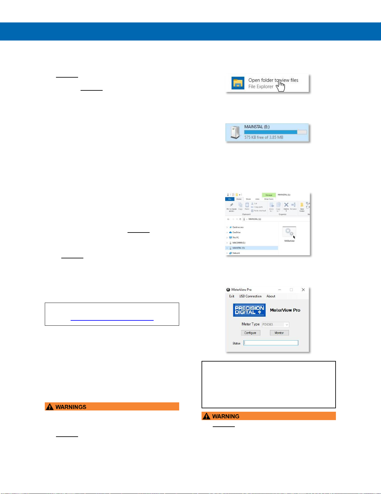
2. Once the driver is installed, an AutoPlay
dialog should appear for the drive
“MAINSTAL.” Click “Open folder to view
files.”
If the computer does not display an AutoPlay
dialog for the drive “MAINSTAL,” you should
open My Computer and double-click on the
drive labeled “MAINSTAL.”
3. Double-click on the file named “MAStart.”
The program will open a few windows and
install two programs on your computer.
Simply follow the on-screen instructions until
you see one of the dialogs below. If you
receive a “User Account Control” warning,
click “Yes.”
4. If there is an update available, click the
“Update” button to install the new version.
Otherwise, click “Configure” to begin
programming your meter.
Note: If you decide to update your MeterView Pro
software, once the installation has completed, you
will be asked if you want to update the setup files
located on the meter itself. This way, you will
always have the most current version on the meter
for future installs.
•DO NOT unplug the meter while the new
installation files are being written to it. The meter
will display uwrite during the process and you
will receive an on-screen notification once the
process is complete.

Helios PD2-6400 High Voltage & High Current Meter
Instruction Manual
15
Connections
All connections are made to screw terminal connectors located under the lower door panel. Remove the single
securing screw in order to access the wiring terminals.
•Use copper wire with 60°C or 60/75°C insulation for all line voltage connections. Observe all safety regulations.
Electrical wiring should be performed in accordance with all applicable national, state, and local codes to prevent
damage to the meter and ensure personnel safety.
Connectors Labeling
The connectors’ label, affixed to the inside of the lower door panel, shows the location of all connectors available with
the ordered configuration.
•DO NOT connect any equipment to the RJ45 M-LINK connector. Otherwise damage will occur to the
equipment and the meter.
•DO NOT disconnect the RJ45 connector located to the left of the power terminal block. Doing so will disable
the on-board digital I/O, and the RS-485 serial communications.
Figure 8. PD2-6400-6H0 / 7H0 Connectors Label
Figure 9. PD2-6400-6H7 / 7H7 Connectors Label
RI-I+
+-
NONC
C
21
1
2
3
4
5
6
7
8
RS-485
DIGITAL I/O
M-LINK
USB
MENU RIGHT UP ACK
POWER
PWR TX RX
DI DI DO DO
O1 O2 O3 O4 G
I1I2I3I4
+5
__ __
NONCCNONCCNONCC
MA OUT
21 3 43 6521 RELAY4RELAY3 43 6521
RELAY2RELAY1
V+ V- F4 COM
214321
I+ I- AC DC
TYPESIGNAL
MENU RESET
F1
MAX
F2
ENTER
F3

Helios PD2-6400 High Voltage & High Current Meter
Instruction Manual
16
Power Connections
Power connections are made to a two-terminal
connector labeled POWER. The meter will operate
regardless of DC polarity connection. The + and -
symbols are only a suggested wiring convention. There
are separate models for low voltage and high voltage
power. See Ordering Information on page 6for
details.
Figure 10. Power Connections
Signal Connections
Signal connections are made to a four-terminal
connector labeled SIGNAL. The I+ and I- terminals
are used for Channel A (CH-A) as the current input
terminals. The V+ and V- terminals are used for
Channel V (CH-V) as the voltage input terminals.
In addition to the signal connections, the switch
labeled TYPE must be set to AC (alternating current)
or DC (direct current) to accept the corresponding
type of voltage and current signals.
Voltage Input
The following figures show examples of connecting the
meter for a voltage input. Note that in addition to the
connections, the AC/DC type switch much also be set.
Figure 11. AC Voltage Input Connection
Figure 12. DC Voltage Input Connections
Current Input
The following figures show examples of connecting the
meter for a current input. Note that in addition to the
connections, the AC/DC type switch much also be set.
Figure 13. AC Current Connections
Figure 14. AC Current Transformer Connections
Figure 15. DC Current Connections
AC or DC
POWER
Required External Fuse:
5 A max, 250 V Slow Blow
POWER
+-
HOT NEUTRAL
INPUT SIGNAL
I- V+I+ V-
3412
COMF4
12
TYPE
AC DC
V
AC
INPUT SIGNAL
I- V+I+ V-
3412
COMF4
12
TYPE
AC DC
V
DC

Helios PD2-6400 High Voltage & High Current Meter
Instruction Manual
17
Current and Voltage Input
The following figures show examples of connecting the
meter for both current and voltage input. Note that in
addition to the connections, the AC/DC type switch
much also be set.
Figure 16. AC Current and Voltage Connections
Figure 17. AC Current Transformer and Voltage
Connections
Figure 18. DC Current and Voltage Connections
Relay Connections
Relay connections are made to two six-terminal
connectors labeled RELAY1 –RELAY4. Each relay’s
C terminal is common only to the normally open (NO)
and normally closed (NC) contacts of the
corresponding relay. The relays’ C terminals should
not be confused with the COM (common) terminal of
the INPUT SIGNAL connector.
Figure 19. Relay Connections
CNONO NC NC C
RELAY4 RELAY3
4 36 5 2 1
CNONO NC NC C
RELAY2 RELAY1
4 36 5 2 1

Helios PD2-6400 High Voltage & High Current Meter
Instruction Manual
18
Switching Inductive Loads
The use of suppressors (snubbers) is strongly
recommended when switching inductive loads to
prevent disrupting the microprocessor’s operation.
The suppressors also prolong the life of the relay
contacts. Suppression can be obtained with resistor-
capacitor (RC) networks assembled by the user or
purchased as complete assemblies. Refer to the
following circuits for RC network assembly and
installation:
Figure 20. AC and DC Loads Protection
Choose R and C as follows:
R: 0.5 to 1 Ωfor each volt across the contacts
C: 0.5 to 1 µF for each amp through closed contacts
Notes:
1. Use capacitors rated for 250 VAC.
2. RC networks may affect load release time of
solenoid loads. Check to confirm proper
operation.
3. Install the RC network at the meter's relay screw
terminals. An RC network may also be installed
across the load. Experiment for best results.
Use a diode with a reverse breakdown voltage two to three
times the circuit voltage and forward current at least as large
as the load current.
Figure 21. Low Voltage DC Loads Protection
RC Networks Available from
Precision Digital
RC networks are available from Precision Digital and
should be applied to each relay contact switching an
inductive load. Part number: PDX6901.
Note: Relays are de-rated to 1/14th HP (50 watts)
with an inductive load.
RS-485 Connections
The RS-485 connections are made to a five terminal
connector used for Modbus®RTU serial
communications. The RS-485 terminals include
Transmit Data (DO) and (/DO), Receive Data (DI) and
(/DI), and Signal Ground. See Modbus RTU Serial
Communications (serial) on page 40 for more
information.
There are three diagnostic LEDs: Power (PWR)
Transmit Data (TX), and Receive Data (RX) to show
when the meter is transmitting and receiving data
from other devices.
Figure 22. RS-485 Connection
RS-485 Multi-Drop Connection
When using more than one meter in a multi-drop
mode, each meter must be provided with its own
unique address. The meter address (Slave ID) can be
programmed between 1 and 247. The transmit delay
can be set between 0 and 199 ms. The parity can be
set to even, odd, or none with 1 or 2 stop bits.
To change the meter address:
1. Press and hold the Menu button for three
seconds to access Advanced Features menu of
the meter.
2. Press Up arrow until Serial (SEriaL) menu is
displayed and press Enter, Addres is displayed.
3. Press Enter to change meter address using Right
and Up arrow buttons. Press Enter to accept.
4. Press Menu button to exit and return to Run
Mode.
RS-485 Serial Converters
To convert the RS-485 to RS-232, use the PDA7485-I
converter. To convert the RS-485 to USB, use the
PDA8485-I converter. See Ordering Information on
page 6for additional information.
C
R
C
R
RS-485
PWR TX RX
DI DI DO DO
__ __

Helios PD2-6400 High Voltage & High Current Meter
Instruction Manual
19
RS-485 Connection Examples
Figure 23. Five-Wire RS-485 Connections
Figure 24. Three-Wire RS-485 Multi-Drop
Connections
Notes:
1. Termination resistors are optional, and values
depend on the cable length and characteristic
impedance. Consult the cable manufacturer for
recommendations.
2. Refer to RS-232 to RS-485 Converter
documentation for further details.
3. Use shielded cable, twisted-pair plus ground.
Connect ground shield only at one location
RS-485 Converter Connections
Figure 25 below details the wiring connections from
the RS-485 connector to an RS-485 serial converter
(such as the PDA7485-I or PDA8485-I) for a five-wire
network.
RS-485 Connector to RS-485
Serial Converter Connections
RS-485 Connector
RS-485 to USB or
RS-232 Converter
DO
DI
DO
DI
DI
DO
DI
DO
Figure 25. Connections for RS-485 Connector to
Serial Converter
Three-Wire Connection
In order to wire the five pins for use as a three-wire
half-duplex RS-485 connection, it is necessary to
create a jumper connection between DI to DO and /DI
to /DO- as shown below.
Figure 26. Three-Wire RS-485 Connection
Digital I/O Connections
Digital inputs and outputs are provided in order to
expand the functionality of the meter. Digital input
connections are made via a push button or switch to
the appropriate digital input terminal and the +5 VDC
terminal. Digital output connections are made by
wiring from the appropriate digital output terminal to
the ground terminal.
Figure 27. Digital Input and Output Connections
Shield
RS-232 Serial
Connection
to PC
R
R
Twisted-Pair
R
DI DI DO DO
__ __
RS-232 to RS-485
Converter
DI
DIDO DO
R
Shield
Twisted-Pair
R
Meter #1
DI DI DO DO
__ __ DI DI DO DO
__ __
Last Meter
RS-232 Serial
Connection
to PC
R
RS-232 to RS-485
Converter
DI
DIDO DO
__ __
DI DI DO DO
O1 O2 O3 O4 G
I1I2I3I4+5
Ground
5 VDC

Helios PD2-6400 High Voltage & High Current Meter
Instruction Manual
20
F4 Digital Input Connections
A digital input, F4, is standard on the meter. This
digital input should be connected with a normally
open contact across F4 and COM, or with an active
low signal applied to F4. It can be used for remote
operation of front-panel buttons, to acknowledge/reset
relays, or to reset max/min values. See Function Keys
& Digital I/O Available Settings on page 42 for a
complete list of capabilities.
Figure 28. F4 Digital Input Connections
4-20 mA Output Connections
Connections for the 4-20 mA transmitter output are
made to the connector terminals labeled MA OUT.
The 4-20 mA output may be powered internally or
from an external power supply.
Figure 29. 4-20 mA Output Connections
Analog Output Transmitter Power
Supply
The internal 24 VDC power supply powering the
analog output may be used to power other devices, if
the analog output is not used. The I+ terminal is the
+24 V and the R terminal is the return.
Figure 30. Analog Output Supply Powering Other
Devices
Remote Operation of Meter
The meter can be operated via the programming
buttons or a PDA2364-MRUE remote control station
using the digital inputs and outputs connections as
illustrated in Figure 31. Meter to PDA2364-MRUE
Control Station Connection.
Figure 31. Meter to PDA2364-MRUE Control
Station Connection
Interlock Relay Feature
As the name implies, the interlock relay feature
reassigns one, or more, alarm/control relays for use
as interlock relay(s). Interlock contact(s) are wired to
digital input(s) and activate the interlock relay. This
feature is enabled by configuring the relay, and the
corresponding digital input(s), see Setting Up the
Interlock Relay (Force On) Feature on page 35.
In the example below, an Interlock Contact switch is
connected to a digital input, which will be used to
force on (energize) the Interlock Relay. The Interlock
Relay and the Control Relay are connected in series
with the load.
•When the Interlock Contact is closed (safe), the
Interlock Relay energizes, allowing power to flow
to the Control Relay; the corresponding front
panel LED is on.
•When the Interlock Contact is open, the
corresponding front panel LED flashes (locked
out), the Interlock Relay is de-energized,
preventing power from flowing to the Control
Relay and the load.
Figure 32. Interlock Connections
COMF4
12
4-20 mA Input
Remote Display, PLC,
Chart Recorder, Etc.
-
+
RI- I+ 132
RELAY1 mA OUT
24 V
12-35 VDC
Power
Supply
+
4-20 mA
Input Meter
-+
RI- I+ 132
RELAY1
321
-
24 V
mA OUT
Internal Power Supply
and Analog Output
321
Active Output Loop Passive Output Loop
RI- I+
132
24 VDC
Powered
Device
24 V
+-
Table of contents
Other Helios Measuring Instrument manuals

 L User manual")


Popular Measuring Instrument manuals by other brands

Bosch
Bosch 0 603 663 B03 instructions

GW Instek
GW Instek GOM-804 Firmware Upgrade Quick Guide

Circutor
Circutor MK-30-LCD user manual

PCE Instruments
PCE Instruments PCE-TG 300-NO2-ICA user manual

TSI Incorporated
TSI Incorporated CA-CALC Operation and service manual

Olympus
Olympus 27MG Getting started guide


