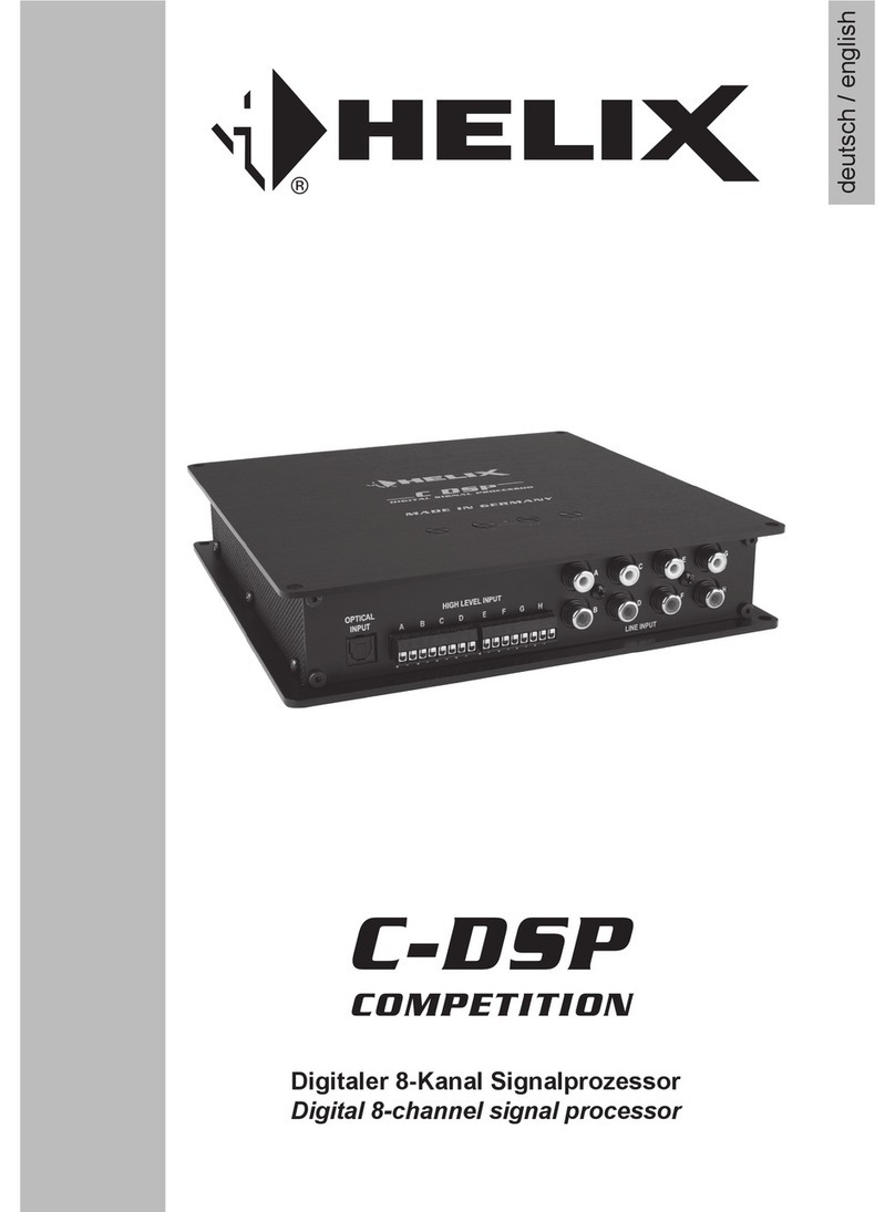
HELIX DSP.2 User manual

DSP.2
Digitaler 8-Kanal Signalprozessor mit
48 kHz / 24 Bit Signalweg
Digital 8-channel signal processor with
48 kHz / 24 Bit signal path
deutsch / english

13
Dear Customer,
&RQJUDWXODWLRQVRQ\RXUSXUFKDVHRIWKLVLQQRYDWLYH
and high-quality HELIX product.
With the HELIX DSP.2, Audiotec Fischer is setting
new standards in the range of digital signal
processors.
We wish you many hours of enjoyment with your
new HELIX DSP.2.
Yours,
AUDIOTEC FISCHER
General installation instructions for HELIX
components
7RSUHYHQWGDPDJHWRWKHXQLWDQGSRVVLEOHLQMXU\
read this manual carefully and follow all installation
instructions. This product has been checked for
proper function prior to shipping and is guaranteed
against manufacturing defects.
Before starting your installation, disconnect
the battery’s negative terminal to prevent
GDPDJHWRWKHXQLW¿UHDQGRUULVNRILQMXU\ For
a proper performance and to ensure full warranty
FRYHUDJHZHVWURQJO\UHFRPPHQGWRJHWWKLVSURG-
uct installed by an authorized HELIX dealer.
Install your HELIX DSP.2 in a dry location with suf-
¿FLHQWDLUFLUFXODWLRQIRUSURSHUFRROLQJRIWKHHTXLS-
ment. The signal processor should be secured to
a solid mounting surface using proper mounting
KDUGZDUH%HIRUH PRXQWLQJFDUHIXOO\ H[DPLQHWKH
area around and behind the proposed installa-
tion location to insure that there are no electrical
cables or components, hydraulic brake lines or any
part of the fuel tank located behind the mounting
surface. Failure to do so may result in unpredictable
damage to these components and possible costly
UHSDLUVWRWKHYHKLFOH
General instruction for connecting the HELIX
DSP.2 signal processor
The HELIX DSP.2 signal processor may only be in-
VWDOOHGLQ YHKLFOHVZKLFK KDYHD 9ROWVQHJDWLYH
terminal connected to the chassis ground. Any other
system could cause damage to the signal processor
DQGWKHHOHFWULFDOV\VWHPRIWKHYHKLFOH
7KH SRVLWLYH FDEOH IURP WKH EDWWHU\ IRU WKH HQWLUH
VRXQGV\VWHPVKRXOGEHSURYLGHGZLWKDPDLQIXVH
DWDGLVWDQFHRIPD[FPIURPWKHEDWWHU\7KH
YDOXH RI WKH IXVH LV FDOFXODWHG IURP WKH PD[LPXP
total current draw of the car audio system.
Use only the provided connectors or the option-
ally available Easy Plug Cable for connection of
the HELIX DSP.2. The use of other cables can
result in damage of the signal processor, the
KHDG XQLW UDGLR RU WKH FRQQHFWHG DPSOL¿HUV
loudspeakers!
Prior to installation, plan the wire routing to
DYRLG DQ\ SRVVLEOH GDPDJH WR WKH ZLUH KDUQHVV
All cabling should be protected against possible
FUXVKLQJ RU SLQFKLQJ KD]DUGV $OVR DYRLG URXWLQJ
cables close to potential noise sources such as
electric motors, high power accessories and other
YHKLFOHKDUQHVVHV
Congratulations!
General instructions

14
Connectors and control units
7Ground lift switch
&DQ EH XVHG WR GH¿QH WKH FRQQHFWLRQ EH-
tween the grounding of the inputs and out-
puts.
8Control pushbutton
Use this button to either switch between the
VHWXSVRULQLWLDWHDUHVHWRIWKHGHYLFH
9Status LED
This LED indicates the operating mode of the
DSP and which setup has been chosen.
10 USB input
Connects the HELIX DSP.2 to your PC.
11 Control Input
Multifunction interface for e.g. an optional
remote control or other HELIX accessory.
12 Line Output
/LQHRXWSXWVIRUFRQQHFWLQJDPSOL¿HUV0DNH
sure that the remote output is used to turn on
WKHVHGHYLFHV
1Line Input
5&$ LQSXWV IRU FRQQHFWLQJ SUHDPSOL¿HU
signals.
2Clipping LED
This LED lights up red if one of the analog
LQSXWVLVRYHUGULYHQ
.3Input Sensitivity
&RQWURO IRU DGMXVWLQJ WKH LQSXW VHQVLWLYLW\ RI
WKHORZDQGKLJKOHYHOLQSXWV
4Highlevel Input
+LJKOHYHO VSHDNHU LQSXWV IRU FRQQHFWLQJ D
factory radio or an aftermarket radio without
pre-amp / line outputs.
5Optical Input
Optical input for digital stereo signals (SPDIF
format).
6Power Input
Connector for the DC power supply with an
additional remote in- and output. The remote
RXWSXWKDVWREHXVHGWRVZLWFKRQH[WHUQDO
DPSOL¿HUV
7 8 9 10 11 12
1
3
42 5 6

15
1Line Input
FKDQQHO SUHDPSOL¿HU LQSXW WR FRQQHFW VLJQDO
VRXUFHV VXFK DV UDGLRV ,QSXW VHQVLWLYLW\ LV
IDFWRU\VHWWR 9ROWVPD[LPXP &&:SRVLWLRQ ,W
LV SRVVLEOH WR YDU\ WKH VHQVLWLYLW\ EHWZHHQ DQG
9ROWV
2Clipping LED
7KLV/('OLJKWVXSUHGLIRQHRIWKHVL[Line Inputs
or Highlevel InputsLVRYHUGULYHQ7KH/('KDVQR
IXQFWLRQLIWKHGHYLFHLVIHGZLWKGLJLWDOLQSXWVLJQDOV
,IWKLV/('OLJKWVXSUHGXFHWKHLQSXWVHQVLWLYLW\E\
using the control 3 (Input Sensitivity) until the LED
goes out.
3Input Sensitivity
7KLVFRQWUROLVXVHGWRDGDSWWKHLQSXWVHQVLWLYLW\RI
WKHORZDQGKLJKOHYHOLQSXWVWRWKHRXWSXWYROWDJH
RIWKHFRQQHFWHGVLJQDOVRXUFH7KLVLVQRWDYROXPH
control, it´s only for adjusting the signal processors
gain. The control range of the RCA / Line Input is
9ROWVDQG9ROWVIRUWKHHighlevel Input.
Attention: It is mandatory to properly adapt the in-
SXWVHQVLWLYLW\RIWKH'63WRWKHVLJQDOVRXUFHLQ
RUGHUWRDYRLGGDPDJHWRWKHVLJQDOSURFHVVRU
If the Highlevel Input is used in combination with a
VWDQGDUGFDUUDGLRZHUHFRPPHQGDQLQSXWVHQVLWLY-
LW\ RI URXJKO\ 9ROWV )RU WKLV SXUSRVH WXUQ WKH
FRQWUROIURP PD[ &&:SRVLWLRQ WRR¶FORFN SRVL-
tion.
4Highlevel Input
FKDQQHO KLJKOHYHO ORXGVSHDNHU LQSXW WR FRQQHFW
the signal processor directly to loudspeaker outputs
RI2(0DIWHUPDUNHWUDGLRVRU2(0DPSOL¿HUVWKDW
GRQRWKDYHDQ\SUHDPSOL¿HURXWSXWV,QSXWVHQVL-
WLYLW\LVIDFWRU\VHWWR9ROWVPD[LPXP&&:SR-
VLWLRQ,WLVSRVVLEOHWRYDU\WKHVHQVLWLYLW\EHWZHHQ
DQG9ROWVZLWKFRQWUROInput Sensitivity).
Attention: Solely use the pluggable screw-terminal
IRUWKHKLJKOHYHOFRQQHFWRUZKLFKLVLQFOXGHGLQGH-
OLYHU\ RU DQ RSWLRQDO DYDLODEOH FDEOH KDUQHVV IURP
the HELIX accessory assortment!
Important: It is strictly forbidden to use the High-
level Input DQG SUHDPSOL¿HU LQSXWV Line Input) at
WKHVDPHWLPH7KLVPD\FDXVHVHYHUHGDPDJHWR
WKHSUHDPSOL¿HURXWSXWVRI\RXUFDUUDGLR
5Optical Input
Optical input in SPDIF format for connecting signal
sources with a digital audio output. The sampling
rate of this input must be between 12 and 96 kHz.
The input signal is automatically adapted to the in-
WHUQDOVDPSOHUDWH,QRUGHUWRFRQWUROWKHYROXPHRI
this input, we recommend to use an optional remote
control.
Notice: This signal processor can only handle ste-
reo input signals and no Dolby-coded digital audio
stream.
6Power Input
This input is used for connecting the signal pro-
FHVVRU WR WKH SRZHU VXSSO\ RI WKH YHKLFOH DQG IRU
UHPRWHLQRXW,IWKHKLJKOHYHOORXGVSHDNHULQSXWV
are used the remote input can be left unconnected.
The remote output is used for turning on/off ampli-
¿HUVWKDWDUHFRQQHFWHGWRWKHLine Outputs of the
HELIX DSP.2. Connect this remote output to the
UHPRWHLQSXWVRI\RXU DPSOL¿HUV7KLVLVHVVHQWLDO
WRDYRLGDQ\LQWHUIHULQJVLJQDOV7KHUHPRWHRXWSXW
LV DFWLYDWHG DXWRPDWLFDOO\ DV VRRQ DV WKH ERRWLQJ
process of the DSP is completed. Additionally this
RXWSXW ZLOO EH WXUQHG RII GXULQJ WKH ³3RZHU 6DYH
Mode” or a software update process.
Attention: Solely use the pluggable screw-terminal
ZKLFKLVLQFOXGHGLQGHOLYHU\
Important: Never use a different signal than the
remote output of the DSP to activate connected
DPSOL¿HUV
7Ground lift switch
The ground of the HELIX DSP.2 signal inputs is gal-
YDQLFDOO\ GHFRXSOHG IURP WKH JURXQG RI WKH VLJQDO
outputs. In many cars this setup is the best way to
DYRLGDOWHUQDWRUQRLVH1HYHUWKHOHVVWKHUHDUHXVH
cases where it will be necessary to directly con-
nect input and output ground or to tie both grounds
WRJHWKHU YLD D UHVLVWRU 7KHUHIRUH WKH Ground lift
switch has three positions:
- center position: input and output ground
separated.
- left position: input and output ground tied
together.
- right position: input and output ground
FRQQHFWHGYLD2KPVUHVLVWRU
Initial start-up and functions

16
8Control pushbutton
The Control pushbutton allows the user to switch
between the two setup memory positions. To switch
between the setups the button has to be pressed
and held for one second. Switching is indicated by
DVLQJOHUHGÀDVKRIWKHStatus LED. Pressing the
EXWWRQIRU¿YHVHFRQGVFRPSOHWHO\HUDVHVWKHLQWHU-
QDOPHPRU\7KLVLVLQGLFDWHGE\DFRQVWDQWÀDVKLQJ
of the Status LED.
Attention: After erasing the setups from memory
the HELIX DSP.2 will not reproduce any audio out-
put.
9Status LED
The Status LED LQGLFDWHV WKH FXUUHQW DFWLYH '63
setup. Green means that setup 1 is loaded, orange
PHDQVWKDWVHWXSLVORDGHG$ÀDVKLQJUHGOLJKWLQ-
dicates that no setup is loaded. In that case please
ORDGDQHZVHWXSYLDWKH'633&7RROVRIWZDUH,I
the LED starts blinking orange, the internal tem-
SHUDWXUHSURWHFWLRQLVDFWLYH$W¿UVWWKHUHPRWHRXW-
put will be turned off. If the temperature still rises the
signal processor will shut down until it has reached
DVDIHWHPSHUDWXUHOHYHODJDLQ
10 USB input
Connect your personal computer to the DSP.2
XVLQJ WKH SURYLGHG 86% FDEOH 7KH UHTXLUHG 3&
VRIWZDUHWRFRQ¿JXUHWKLVVLJQDOSURFHVVRUFDQEH
downloaded from the Audiotec Fischer website
ZZZDXGLRWHF¿VFKHUFRP.
Please note: It is not possible to connect any USB
VWRUDJHGHYLFHV
11 Control Input
This multi-functional input is designed for HELIX
DSP.2 accessory products like a remote control
ZKLFKDOORZVWRDGMXVWVHYHUDOIHDWXUHVRIWKHVLJQDO
processor. Depending on the type of remote con-
WURODW¿UVWLWVIXQFWLRQDOLW\KDVWREHGH¿QHGLQWKH
³'HYLFH &RQ¿JXUDWLRQ 0HQX´ RI WKH '63 3&7RRO
software.
12 Line Output
FKDQQHO SUHDPSOL¿HU RXWSXW IRU FRQQHFWLQJ SR
ZHU DPSOL¿HUV 7KH RXWSXW YROWDJH LV 9ROWV PD[
3OHDVHPDNHVXUHWKDW\RXDOZD\VWXUQRQRIIH[WHU-
QDODPSOL¿HUVXVLQJWKHUHPRWHRXWSXWRIWKHVLJQDO
processors Power Input1HYHUGLUHFWO\FRQWUROWKH
H[WHUQDODPSVE\ DVLJQDOIURPWKH LJQLWLRQVZLWFK
of your car! Additionally this output will be turned
RIIZKHQWKH³3RZHU6DYH0RGH´RIWKHVLJQDOSUR-
FHVVRU LV DFWLYH 7KH RXWSXWV FDQ EH DVVLJQHG WR
any of the inputs as desired using the DSP PC-Tool
software.
Initial start-up and functions

17
Installation
Connection of HELIX DSP.2 to the head unit/car
radio:
Caution: Carrying out the following steps will re-
quire special tools and technical knowledge. In or-
GHUWRDYRLGFRQQHFWLRQPLVWDNHVDQGRUGDPDJH
DVN\RXUGHDOHUIRUDVVLVWDQFHLI\RXKDYHDQ\TXHV
tions and follow all instructions in this manual (see
SDJH,WLVUHFRPPHQGHGWKDWWKHGHYLFHZLOOEH
installed by an authorized HELIX dealer.
&RQQHFWLQJWKHSUHDPSOL¿HULQSXWV
Use the correct cable (RCA / cinch cable) to
FRQQHFW WKHVH LQSXWV WR WKH SUHDPSOL¿HU
ORZOHYHOFLQFKRXWSXWVRI\RXUFDUUDGLR(DFK
input can be assigned to any output using the
DSP PC-Tool software. The automatic turn-on
circuit does not work when using the pre-ampli-
¿HULQSXWV,QWKLVFDVHWKHUHPRWHLQSXWKDVWR
EHFRQQHFWHGWRDFWLYDWHWKH+(/,;'63
Important: It is strictly forbidden to use the
Highlevel Input DQG SUHDPSOL¿HU LQSXWV Line
InputDWWKHVDPHWLPH7KLVPD\FDXVHVHYHUH
GDPDJHWRWKHSUHDPSOL¿HURXWSXWVRI\RXUFDU
radio.
2. Connecting the highlevel speaker inputs
7KH KLJKOHYHO ORXGVSHDNHU LQSXWV FDQ EH FRQ-
nected directly to the loudspeaker outputs of an
OEM or aftermarket radio using appropriate ca-
EOHVORXGVSHDNHUFDEOHVZLWKPPð$:*
PD[
We recommend the following channel assign-
ment if a common car radio will be connected to
the signal processor:
Channel A = Front left
Channel B = Front right
Channel C = Rear left
Channel D = Rear right
$FWXDOO\LWLVQRWPDQGDWRU\WRXVHDOOKLJKOHYHO
speaker inputs. If only two channels will be con-
nected we recommend to use the channels A
and B. Make sure that the polarity is correct. If
RQHRUPRUHFRQQHFWLRQVKDYHUHYHUVHGSRODU-
ity it may affect the performance of the signal
processor. If this input is used the remote input
does not need to be connected as the signal
processor will automatically turn on once a
ORXGVSHDNHUVLJQDOLVUHFHLYHG
$GMXVWPHQWRIWKHLQSXWVHQVLWLYLW\
Attention: It is mandatory to properly adapt
the input sensitivity of the DSP.2 to the sig-
nal source in order to avoid damage to the
signal processor.
,I\RXZDQWWRFKDQJHWKHLQSXWVHQVLWLYLW\XVH
the control 3 (see page 15 item 3; Input Sensi-
tivity). The setting of the control affects both the
ORZOHYHODQGWKHKLJKOHYHOLQSXWV
Follow the subsequent steps to perfectly adapt
WKH VLJQDO SURFHVVRUV LQSXW VHQVLWLYLW\ WR \RXU
audio source by using the control:
'RQµWFRQQHFWDQ\DPSOL¿HUVWRWKHRXWSXWV
of the HELIX DSP.2 during this setup.
2. Turn on the signal processor.
$GMXVW WKH YROXPH RI \RXU UDGLR WR DSSUR[
RI WKH PD[ YROXPH DQG SOD\EDFN D
N+]IXOOVFDOHWHVWWRQHG%YLD&'GULYH
4. If the Clipping LED already lights up, you
KDYHWRUHGXFHWKHLQSXWVHQVLWLYLW\YLDFRQ-
trol (page 15 item 3; Input Sensitivity) until
the LED turns off.
,QFUHDVHWKHLQSXWVHQVLWLYLW\E\WXUQLQJWKH
control clockwise until the LED lights up.
Now turn the control counterclockwise until
the Clipping LED turns off again.
If the Highlevel Input is used in combination
with a standard car radio we recommend an in-
SXW VHQVLWLYLW\ RI URXJKO\ 9ROWV )RU WKLV SXU-
SRVHWXUQWKHFRQWUROIURPPD[&&:SRVLWLRQ
WRR¶FORFNSRVLWLRQ
4. Connecting a digital signal source
,I\RXKDYHDVLJQDOVRXUFHZLWKDQRSWLFDOGLJL
tal output you can connect it to the signal pro-
cessor using the appropriate input. In standard
FRQ¿JXUDWLRQ WKH +(/,; '63 DXWRPDWLFDOO\
DFWLYDWHVWKHXVHGGLJLWDOLQSXWLIDGLJLWDODXGLR
signal is detected. This function can be deac-
WLYDWHGYLDWKH'633&7RROVRIWZDUH$OWHUQD-
WLYHO\\RXFDQPDQXDOO\DFWLYDWHWKHGLJLWDOLQSXW
if you are using the optional remote control. The
automatic turn-on circuit does not work when
the digital input is used. Therefore it is manda-
tory to connect the remote input of the Power
Input. Please note that it is possible to connect
a source to the digital input and the Highlevel
Input or the Line Input at the same time.
Important: The signal of a digital audio source

18
normally does not contain any information
DERXWWKHYROXPHOHYHO.HHSLQPLQGWKDWWKLV
ZLOOOHDGWRIXOOOHYHORQWKHRXWSXWVRIWKH+(/,;
'63DQG\RXUFRQQHFWHGDPSOL¿HUV7KLVPD\
FDXVH VHYHUH GDPDJH WR \RXU VSHDNHUV :H
strongly recommend to use an optional remote
FRQWUROIRUDGMXVWLQJWKHYROXPHOHYHORIWKHGLJ-
ital signal input!
Information: The HELIX DSP.2 can only han-
dle uncompressed digital stereo signals in PCM
format with a sample rate between 12 kHz and
96 kHz and no Dolby-coded signals.
5. Connection to power supply
Make sure to disconnect the battery before
installing the HELIX DSP.2!
Solely use the included screw-type terminal
to connect the HELIX DSP.2 to a power sup-
ply. Make sure of correct polarity. The ground
ZLUHPXVWEHFRQQHFWHGWRWKHYHKLFOHFKDVVLV
at a non-insulated point. Inadequate grounding
causes audible interference and malfunctions.
7KH SRVLWLYH ZLUH KDV WR EH FRQQHFWHG WR WKH
EDWWHU\¶V SRVLWLYH SRVW RU D SRZHU GLVWULEXWLRQ
block. Though the current draw of the HELIX
'63 LV UDWKHU ORZ DSSUR[ P$ ZH UHF-
RPPHQG D PLQLPXP ZLUH JDXJH RI PPð
AWG18 for both power supply wires.
6. Connecting the remote input
The remote input of the Power Input has to be
connected to the radio remote output if the sig-
QDOSURFHVVRUVSUHDPSOL¿HULQSXWVRUWKHOpti-
cal Input are solely used as signal inputs. We
do not recommend controlling the remote input
YLDWKHLJQLWLRQVZLWFKWRDYRLGSRSQRLVHGXULQJ
turn on/off. If the Highlevel Input is used this in-
put does not need to be connected as long as
the car radio has BTL output stages.
&RQ¿JXUDWLRQRIWKHUHPRWHLQSXW
The DSP.2 will be turned on automatically if the
Highlevel Input is used or if a signal is applied
to the remote input terminal. The “Auto Remote”
VZLWFKDOORZVWRGHDFWLYDWHWKHDXWRPDWLFWXUQ
RQIHDWXUH7KHIHDWXUHVKRXOGEHGHDFWLYDWHGLI
there are e.g. noises while switching on/off the
signal processor.
Note: If the automatic turn-on function is deac-
WLYDWHGLWLVPDQGDWRU\WRXVHWKHUHPRWHLQSXW
terminal to power up the signal processor! The
KLJKOHYHOVLJQDOZLOOEHLJQRUHGLQWKLVFDVH
Note:7KHDFWLYDWLRQRIWKHVLJQDOSURFHVVRUYLD
VSHDNHULQSXWLVDFWLYDWHGH[ZRUNV
7R GHDFWLYDWH WKH DXWRPDWLF WXUQRQ IHDWXUH
\RX KDYH WR RSHQ WKH GHYLFH DQG FKDQJH WKH
position of the “Auto Remote” switch. Therefore
dismantle the side panel (where the USB input
LV ORFDWHG E\ UHPRYLQJ WKH ¿YH VFUHZV IRXU
Phillips screws and one allen screw). Now you
can pull out the bottom plate and get access to
the switch. The switch is located near by the
KLJKOHYHO VSHDNHU LQSXWV VHH PDUNLQJ LQ WKH
following picture).
On: $FWLYDWLRQ YLD KLJKOHYHO VSHDNHU LQSXW LV
HQDEOHGH[ZRUNV
Off: $FWLYDWLRQ YLD KLJKOHYHO VSHDNHU LQSXW LV
disabled.
&RQ¿JXUDWLRQRIWKH'63
The general DSP settings should be con-
ducted with the DSP PC-Tool software be-
IRUHXVLQJWKHVLJQDOSURFHVVRUIRUWKH¿UVW
time.
,JQRULQJWKLVDGYLFHPD\UHVXOWLQGDPDJLQJWKH
FRQQHFWHGDPSOL¿HUVWKHORXGVSHDNHUV,QIRU-
mation about connecting the DSP.2 to a com-
puter can be found on page 21.
9. Connecting the remote output
This output (Remote out) is used to supply re-
PRWHVLJQDOVWRWKHH[WHUQDODPSOL¿HUV$OZD\V
use this remote output signal to turn on the am-
SOL¿HUVLQRUGHUWRDYRLGRQRIIVZLWFKLQJQRLVHV
Installation

19
Smart highlevel input
The latest generation of OE car radios incorporates
sophisticated possibilities of diagnosing the con-
nected speakers. If a common signal processor will
EHKRRNHGXSIDLOXUHPHVVDJHVDQGORVVRIVSHFL¿F
features (e.g. fader function) quite often appears -
but not with the DSP.2.
7KHQHZ$'(3FLUFXLW$GYDQFHG'LDJQRVWLFV(UURU
3URWHFWLRQDYRLGVDOOWKHVHSUREOHPVZLWKRXWORDG-
ing the speaker outputs of the OE radio during high
YROXPHVXQQHFHVVDULO\
Power Save Mode
7KH3RZHU6DYH0RGHLVLQFRUSRUDWHGLQWKHEDVLF
VHWXS ,W DOORZV WR VLJQL¿FDQWO\ UHGXFH WKH SRZHU
FRQVXPSWLRQRIWKHDPSOL¿HUVWKDWDUHFRQQHFWHGWR
WKH+(/,;'63RQFHWKHUH¶VQRLQSXWVLJQDOSUHV-
ent for more than 60 seconds. Please note that in
many up-to-date cars with “CAN” or any other in-
ternal bus structures it may happen that the radio
UHPDLQV³LQYLVLEO\´WXUQHGRQIRUXSWRPLQHYHQ
DIWHUORFNLQJDQGOHDYLQJWKHFDU2QFHWKH³3RZHU
6DYH0RGH³LVDFWLYHWKHUHPRWHRXWSXWDQGWKHUH-
IRUHWKHFRQQHFWHGDPSOL¿HUVZLOOEHWXUQHGRII7KH
+(/,;'63ZLOOUHDFWLYDWHWKHUHPRWHRXWSXWZLWK-
in a second if a music signal is applied. It is possible
to either modify the turn-off time of 60 sec. or com-
SOHWHO\ GHDFWLYDWH WKH ³3RZHU 6DYH 0RGH´ YLD WKH
DSP PC-Tool software.
Start-Stop capability
The switched power supply of the HELIX DSP.2
DVVXUHVD FRQVWDQWLQWHUQDO VXSSO\YROWDJH HYHQLI
WKHEDWWHU\¶VYROWDJHGURSVWR9ROWVGXULQJHQJLQH
crank.
Automatic Digital Signal Detection
Switching from analog input to the digital input is
done automatically as soon as a signal is detected
on the Optical Input. This feature can be deacti-
YDWHG LQ WKH '63 3&7RRO VRIWZDUH $OWHUQDWLYHO\
you can use an optional remote control for manual
switching between analog and digital inputs.
Unique Features of the HELIX DSP.2

20
Installation with “Easy Plug Cable”
To simplify installation to an OEM or aftermarket
radio the HELIX DSP.2 can also be connected us-
ing the optional Easy Plug Cable (EPC 5) which will
supply the signal processor with both power and
loudspeaker signals of the radio. No factory wires
or plugs need to be cut by using this connection
PHWKRG 7KH (DV\ 3OXJ &DEOH XVHV WKH KLJKOHYHO
inputs A - D.
Connection to an OEM radio is detailed below:
1. 2QFHWKHUDGLRKDVEHHQUHPRYHGE\XVLQJWKH
right tools disconnect the OEM harness from
WKHUDGLR&RQQHFWWKHYHKLFOHFDEOHMDFNFRQ-
nectors of the Easy Plug Cable. You may need
D VSHFLDO ,62DGDSWRU GHSHQGLQJ RQ YHKLFOH
W\SH,QRUGHUWRYHULI\SOHDVHFKHFNWKHDGDSWRU
database on the Audiotec Fischer homepage
ZZZDXGLRWHF¿VFKHUFRP.
2. Connect the cable plugs to the car radio.
3. &RQQHFW WKH KLJKOHYHO SOXJ SROH FRQQHFWRU
and the power supply plug (4-pole connector) of
the Easy Plug Cable to the appropriate HELIX
DSP.2 inputs (Highlevel Input A to D resp. Pow-
er Input).
4. Please note when connecting the power sup-
SO\WKHSHUPDQHQWDQGVZLWFKHG9ROWVZLUHV
PD\ EH UHYHUVHG GHSHQGLQJ RQ YHKLFOH W\SH
The HELIX DSP.2 should not be plugged into
WKHSRZHUVXSSO\YLDWKHLJQLWLRQFDEOHDVWKLV
may cause interferences. Before connecting
WKH(DV\3OXJ&DEOHWRWKH+(/,;'63YHUL-
¿FDWLRQRIWKHSHUPDQHQW9ROWVZLUHPXVWEH
made between the blue and red wires coming
from the ISO connectors of the harness with
D YROWPHWHU 7KH SHUPDQHQW 9ROWV ZLUH ZLOO
VKRZ YROWDJH HYHQ ZLWK WKH YHKLFOH LJQLWLRQ
WXUQHG RII 2QFH WKH FRUUHFW ZLUH LV LGHQWL¿HG
connect the red wire with jack to the corre-
sponding blue or red wire with plug. The pos-
LWLYHFDEOHRIWKHKDUQHVVXVXDOO\KDVDIXVHRI
PD[$
Attention:7KHH[IDFWRU\FRQGLWLRQLVWKDWWKH
UHGZLUHVDUHFRQQHFWHG,I\RX¶UHXQFHUWDLQRI
assignment ask your dealer.
Note - Cars equipped with MOST bus:
In cars equipped with MOST bus structure it is
PDQGDWRU\WRXQSOXJWKH¿EHURSWLFFDEOHIURPWKH
original radio connector and insert it into the ISO
adaptor which has a dedicated recess for this.

21
,W LV SRVVLEOH WR IUHHO\ FRQ¿JXUH WKH +(/,; '63
with our DSP PC-Tool software.
The user interface is designed for easy handling of
DOOIXQFWLRQVDQGDOORZVDQLQGLYLGXDODGMXVWPHQWRI
each of the eight DSP channels. Prior to connecting
WKH VLJQDO SURFHVVRU WR \RXU 3& YLVLW RXU ZHEVLWH
DQGGRZQORDGWKHODWHVWYHUVLRQRIWKH'633&7RRO
software.
Check from time to time for software updates. You
ZLOO¿QGWKHVRIWZDUHDQGWKHUHVSHFWLYHXVHUPDQX-
al on ZZZDXGLRWHF¿VFKHUFRP.
We strongly recommend to carefully read the user
manual (Sound Tuning Magazine) before using the
VRIWZDUHIRUWKH¿UVWWLPHLQRUGHUWRDYRLGDQ\FRP-
plications and failures.
Important: Make sure that the signal processor is
not connected to your computer before the software
DQG86%GULYHUDUHLQVWDOOHG
In the following the most important steps how to
FRQQHFWDQGWKH¿UVWVWDUWXSDUHGHVFULEHG
1. 'RZQORDG WKH ODWHVW YHUVLRQ RI WKH '63
3&7RRO VRIWZDUH DYDLODEOH RQ RXU ZHEVLWH
ZZZDXGLRWHF¿VFKHUFRP) and install it on
your computer.
2. Connect the signal processor to your computer
XVLQJWKH86%FDEOHWKDWLVLQFOXGHGLQGHOLYHU\
,I \RX KDYH WR EULGJH ORQJHU GLVWDQFHV SOHDVH
XVH DQ DFWLYH 86% H[WHQVLRQ FDEOH ZLWK LQWH-
JUDWHGUHSHDWHUDQGQRSDVVLYHH[WHQVLRQ
3. Turn on the signal processor and start the soft-
ware after the Status LED lights up green. The
operating software will be updated automatical-
O\WRWKHODWHVWYHUVLRQLILWLVQRWXSWRGDWH
4. 1RZ \RX DUH DEOH WR FRQ¿JXUH \RXU +(/,;
'63ZLWKRXULQWXLWLYH'633&7RROVRIWZDUH
1HYHUWKHOHVV LQWHUHVWLQJ DQG XVHIXO KLQWV FDQ
be found e.g. in our “Sound Tuning Magazine”,
which can be downloaded for free from our
website.
Caution: :H KLJKO\ UHFRPPHQG WR VHW WKH YRO-
ume of your car radio to minimum position during
¿UVW VWDUWXS $GGLWLRQDOO\ QR GHYLFHV VKRXOG EH
connected to the signal processor until general
VHWWLQJV LQ WKH '63 3&7RRO VRIWZDUH KDYH EHHQ
made. Especially if the DSP.2 will be used in fully
DFWLYHDSSOLFDWLRQVDZURQJVHWXSFDQGHVWUR\\RXU
speakers right away.
Connection to a PC
1/RDGDQGVDYH
2Main menu
3Channel configuration
4Highpass filter
5Lowpass filter
6Time alignment
72XWSXWOHYHO
8Frequency graph
9Range of frequency graphs
10 Equalizer
11 EQ fine adjustment
8
1
6
3
4
7
5
2
9
10 11

22
HELIX Extension Card slot (HEC slot)
,W LV SRVVLEOH WR H[WHQG WKH IXQFWLRQDOLW\ RI WKH
+(/,;'63E\LQVHUWLQJDQRSWLRQDO+(/,;([WHQ-
VLRQ&DUG+(&IRUH[DPSOHDBluetooth®Audio
Streaming module, an additional optical digital in-
put, an AUX input or an USB audio input.
7R LQVWDOO D +(/,; ([WHQVLRQ &DUG LW LV QHFHVVDU\
WRUHPRYHWKHVLGHSDQHORIWKH'63DQGUHSODFH
it by the new side panel that comes with the HEC
module.
Attention: Install the HEC module only in the
GHVLJQDWHG GHYLFH DQG LWV VSHFL¿F VORW 8VLQJ
the HEC module in other devices or slots can
result in damage of the HEC module, the signal
processor, the head unit / car radio or other con-
nected devices!
Read in the following the steps how to install a HEC
module:
1. First disconnect allFDEOHVIURPWKHGHYLFH
2. Dismantle the side panel where the USB input
LVORFDWHGE\UHPRYLQJWKHIRXU3KLOOLSVVFUHZV
and one allen screw.
3. Pull out the bottom plate sideways.
4. Prepare the module for installing it into the de-
YLFH $Q\ IXUWKHU PRXQWLQJ LQIRUPDWLRQ ZLOO EH
IRXQGLQWKHLQVWUXFWLRQPDQXDORIWKHUHVSHFWLYH
HEC module.
5. ,QVHUW WKH +(& PRGXOH LQWR WKH VSHFL¿F VORW
RIWKH GHYLFH ZKLFKLV PDUNHGLQWKH IROORZLQJ
picture.
6. Make sure that the HEC module is installed
properly and all pins are fully inserted into the
socket.
7. 5HLQVHUWWKHERWWRPSODWHDQG¿[WKHQHZVLGH
SDQHO ZKLFK LV GHOLYHUHG ZLWK WKH +(& PRG-
ule with the four Phillips screws and one allen
screw.
8. Bolt the HEC module to the side panel. Precise
mounting information will be found in the in-
VWUXFWLRQPDQXDORIWKHUHVSHFWLYH+(&PRGXOH
9. 5HFRQQHFWDOOFDEOHVWRWKHGHYLFH
10. Turn on the signal processor. The HEC module
LVDXWRPDWLFDOO\GHWHFWHGE\WKHGHYLFHDQGWKH
Status LED of the HEC module lights up green.
11. 1RZ\RXDUHDEOHWRFRQ¿JXUHWKH+(&PRGXOH
in the DSP PC-Tool software.

23
The limited warranty comply with legal regulations.
)DLOXUHV RU GDPDJHV FDXVHG E\ RYHUORDG RU LP-
SURSHUXVHDUHQRWFRYHUHGE\WKHZDUUDQW\3OHDVH
UHWXUQWKHGHIHFWLYHSURGXFWRQO\ZLWKDYDOLGSURRI
of purchase and a detailed malfunction description.
7HFKQLFDOVSHFL¿FDWLRQVDUHVXEMHFWWRFKDQJH
(UURUV DUH UHVHUYHG )RU GDPDJHV RQ WKH YHKLFOH
DQG WKH GHYLFH FDXVHG E\ KDQGOLQJ HUURUV RI WKH
GHYLFH ZH FDQ¶W DVVXPH OLDELOLW\ 7KLV SURGXFW LV
WDJJHGZLWKD&(&HUWL¿NDWLRQPDUN7KHUHE\WKHVH
GHYLFHV DUH FHUWL¿HG IRU WKH XVH LQ YHKLFOHV ZLWKLQ
the European Community (EC).
Technical Data
Warranty Disclaimer
Note:
“The Bluetooth®word mark and logos are registered trademarks owned by Bluetooth SIG, Inc. and any use of such marks by
$XGLRWHF)LVFKHU*PE+LVXQGHUOLFHQVH2WKHUWUDGHPDUNVDQGWUDGHQDPHVDUHWKRVHRIWKHLUUHVSHFWLYHRZQHUV´
Inputs...............................................................................[5&$&LQFK
[+LJKOHYHOVSHDNHULQSXW
[2SWLFDO63',)N+]
[5HPRWH,Q
,QSXWVHQVLWLYLW\................................................................5&$&LQFK9ROWV
+LJKOHYHO9ROWV
Outputs............................................................................[5&$&LQFK
[5HPRWH2XW
2XWSXWYROWDJH .................................................................9ROWV
Frequency response........................................................10 Hz - 22,000 Hz
DSP resolution.................................................................64 Bit
DSP power ......................................................................295 MHz (1.2 billion MAC operations/second)
DSP type .........................................................................Audio signal processor
6LJQDOFRQYHUWHUV.............................................................A/D: BurrBrown
D/A: BurrBrown
Signal-to-noise ratio digital input .....................................112 dB (A-weighted)
Signal-to-noise ratio analog input....................................107 dB (A-weighted)
Total harmonic distortion (THD+N) digital input...............< 0.0008 %
Total harmonic distortion (THD+N) analog input .............< 0.002 %
IM distortion (IMD) digital input........................................< 0.003 %
IM distortion (IMD) analog input ......................................< 0.005 %
Crosstalk..........................................................................> 90 dB
2SHUDWLQJYROWDJH ............................................................9ROWVPD[VHFGRZQWR9ROWV
Current draw....................................................................< 480 mA
0D[UHPRWHRXWSXWFXUUHQW .............................................500 mA
Additional features...........................................................HEC slot, Ground lift switch, Control Input,
ADEP circuit, Auto Remote switch
'LPHQVLRQV+[:[' ..................................................[[PP[[´

Audiotec Fischer GmbH
Hünegräben 26 · 57392 Schmallenberg · Germany
7HOā)D[
(PDLOKHOL[#DXGLRWHF¿VFKHUFRPā,QWHUQHWZZZDXGLRWHF¿VFKHUFRP
Table of contents
Other HELIX Computer Hardware manuals
Popular Computer Hardware manuals by other brands

Huananzhi
Huananzhi P55 user manual

ADLINK Technology
ADLINK Technology PCIe-ACC100 user manual
Renesas
Renesas MCK-RX26T quick start guide
Shugart
Shugart SA810 owner's manual
Siemens
Siemens SIMATIC S7-300 CPU Data: CPU 315-T-2 DP Installation and operating instructions
One Stop Systems
One Stop Systems OSS-PCIe-HIB2-EC-x1 user manual
