Helmer Scientific i Series Installation and user guide

360127-D/E
Freezer Service and Maintenance Manual
i.Series®and Horizon Series™ - Undercounter
360417/A
Laboratory
i.Series
iLF105-GX
Horizon Series
HLF105-GX
Plasma Storage
i.Series
iBF105-GX
Horizon Series
HBF105-GX

Document Updates
The document is furnished for information use only, is subject to change without notice and should not be construed as a
commitment by Helmer Scientic. Helmer Scientic assumes no responsibility or liability for any errors or inaccuracies that may
appear in the informational content contained in this material. For the purpose of clarity, Helmer Scientic considers only the most
recent revision of this document to be valid.
Notices and Disclaimers
Condential / Proprietary Notices
Use of any portion(s) of this document to copy, translate, disassemble or decompile, or create or attempt to create by reverse
engineering or otherwise replicate the information from Helmer Scientic products is expressly prohibited.
Copyright and Trademark
Copyright © 2021 Helmer, Inc. Helmer®, i.Series®, i.C³®, Horizon Series™, and Rel.i™ are registered trademarks or trademarks of
Helmer, Inc. in the United States of America. All other trademarks and registered trademarks are the property of their respective
owners. Helmer, Inc., doing business as (DBA) Helmer Scientic and Helmer.
Disclaimer
This manual is intended as a guide to provide the operator with necessary instructions on the proper use and maintenance of
certain Helmer Scientic products.
Any failure to follow the instructions as described could result in impaired product function, injury to the operator or others, or void
applicable product warranties. Helmer Scientic accepts no responsibility for liability resulting from improper use or maintenance of
its products.
The screenshots and component images appearing in this guide are provided for illustrative purposes only, and may vary slightly
from the actual software screens and/or product components.
Helmer Scientic
14400 Bergen Boulevard
Noblesville, IN 46060 USA
www.helmerinc.com
Part No. 360417/A
Document History
Revision Date CO Supersession Revision Description
A 25 Jan 2021 15824 n/a Initial release.
* Date submitted for Change Order review. Actual release date may vary.

Helmer Scientic i.Series® and Horizon Series™Freezer - Undercounter Service and Maintenance Manual
360417/A 2
Contents
1 About This Manual...................................................................................4
1.1 Intended Audience...............................................................................4
1.2 Model Reference................................................................................4
1.3 Intended Use...................................................................................4
1.4 Safety Symbols and Precautions. . . . . . . . . . . . . . . . . . . . . . . . . . . . . . . . . . . . . . . . . . . . . . . . . . . . . . . . . . . . . . . . . . . . 4
1.5 Avoiding Injury..................................................................................5
1.6 Model and Input Power ...........................................................................5
1.7 Product Labels. . . . . . . . . . . . . . . . . . . . . . . . . . . . . . . . . . . . . . . . . . . . . . . . . . . . . . . . . . . . . . . . . . . . . . . . . . . . . . . . . . 6
i.Series Information............................................................................7
2 InstallationandConguration .........................................................................7
2.1 Location Requirements ...........................................................................7
2.2 Placement and Leveling ..........................................................................7
2.3 Stacked Undercounter Units .......................................................................7
2.4 Connect Back-Up Power..........................................................................8
2.5 Prepare for Monitoring............................................................................8
2.6 CongureStorage ...............................................................................11
2.7 Optional Adapter Kits for Medication Dispensing Locks .................................................12
2.8 Reverse Door Hinges and Handle..................................................................13
3 Controls...........................................................................................17
3.1 Home Screen and Screensaver ...................................................................17
3.2 Home Screen Functions .........................................................................17
3.3 Alarm Reference ...............................................................................17
3.4 Settings ......................................................................................18
3.5 Sensor Calibration..............................................................................22
4 Maintenance . . . . . . . . . . . . . . . . . . . . . . . . . . . . . . . . . . . . . . . . . . . . . . . . . . . . . . . . . . . . . . . . . . . . . . . . . . . . . . . . . . . . . . . 26
4.1 Alarm Tests ...................................................................................27
4.2 Test and Replace Back-up Batteries ................................................................29
4.3 Check Probe Bottle .............................................................................30
4.4 Upper and Lower Door Hinge Cams ................................................................30
4.5 Display Board Battery ...........................................................................30
4.6 Upgrade System Firmware .......................................................................30
4.7 Clean the Freezer ..............................................................................30
5 Service. . . . . . . . . . . . . . . . . . . . . . . . . . . . . . . . . . . . . . . . . . . . . . . . . . . . . . . . . . . . . . . . . . . . . . . . . . . . . . . . . . . . . . . . . . . . 32
5.1 Refrigerant....................................................................................32
5.2 Remove/Replace Unit Cooler Cover ................................................................32
6 Troubleshooting.................................................................................... 34
6.1 Access System Problems ........................................................................34
6.2 Alarm Activation Problems. . . . . . . . . . . . . . . . . . . . . . . . . . . . . . . . . . . . . . . . . . . . . . . . . . . . . . . . . . . . . . . . . . . . . . . . 34
6.3 Chamber Temperature Problems ..................................................................35
6.4 Condensation and Icing Problems. . . . . . . . . . . . . . . . . . . . . . . . . . . . . . . . . . . . . . . . . . . . . . . . . . . . . . . . . . . . . . . . . . 35
7 i.Series Parts. . . . . . . . . . . . . . . . . . . . . . . . . . . . . . . . . . . . . . . . . . . . . . . . . . . . . . . . . . . . . . . . . . . . . . . . . . . . . . . . . . . . . . . 36
8 Schematics ........................................................................................39
8.1 iBF and iLF Models .............................................................................39

Helmer Scientic i.Series® and Horizon Series™Freezer - Undercounter Service and Maintenance Manual
360417/A 3
Horizon Series Information.....................................................................41
9 InstallationandConguration ........................................................................41
9.1 Location Requirements ..........................................................................41
9.2 Placement and Leveling .........................................................................41
9.3 Stacked Undercounter Units ......................................................................41
9.4 Connect Back-Up Power.........................................................................42
9.5 Defrost Events.................................................................................42
9.6 Prepare for Monitoring...........................................................................43
9.7 CongureStorage ..............................................................................46
9.8 Optional Adapter Kits for Medication Dispensing Locks .................................................47
9.9 Reverse Door Hinges and Handle..................................................................48
10 Controls...........................................................................................52
10.1 Monitor and Control Interface .....................................................................52
10.2 Alarm Reference ...............................................................................54
10.3 Settings ......................................................................................55
11 Maintenance .......................................................................................58
11.1 Alarm Tests ...................................................................................59
11.2 Test and Replace Back-up Batteries ................................................................60
11.3 Check Probe Bottle .............................................................................61
11.4 Upper and Lower Door Hinge Cams ................................................................61
11.5 Clean the Freezer ..............................................................................61
12 Service. . . . . . . . . . . . . . . . . . . . . . . . . . . . . . . . . . . . . . . . . . . . . . . . . . . . . . . . . . . . . . . . . . . . . . . . . . . . . . . . . . . . . . . . . . . . 62
12.1 Refrigerant....................................................................................62
12.2 Remove / Replace Unit Cooler Cover ...............................................................62
13 Troubleshooting.................................................................................... 64
13.1 Access System Problems ........................................................................64
13.2 Alarm Activation Problems. . . . . . . . . . . . . . . . . . . . . . . . . . . . . . . . . . . . . . . . . . . . . . . . . . . . . . . . . . . . . . . . . . . . . . . . 64
13.3 Chamber Temperature Problems ..................................................................65
13.4 Condensation and Icing Problems. . . . . . . . . . . . . . . . . . . . . . . . . . . . . . . . . . . . . . . . . . . . . . . . . . . . . . . . . . . . . . . . . . 65
14 Horizon Series Parts ................................................................................66
15 Schematics ........................................................................................69
15.1 HBF and HLF Models ...........................................................................69
15.2 HBF and HPF Models (without Access Control) .......................................................70
15.3 HBF and HLF Models (with Access Control)..........................................................71
Appendix A: Compliance ................................................................................72
Safety Compliance...................................................................................72
Environmental Compliance ............................................................................72
Appendix B: Warranty...................................................................................73

Helmer Scientic i.Series® and Horizon Series™Freezer - Undercounter Service and Maintenance Manual
360417/A 4
1 About This Manual
1.1 Intended Audience
This manual provides information on how to use i.Series®and Horizon Series™undercounter laboratory, and plasma storage
freezers. It is intended for use by end users of the freezer and authorized service technicians.
1.2 Model Reference
Models are indicated by a distinguishing model number that corresponds to the series, type, number of doors, and capacity of the
freezer. For example, “iLF105-GX” refers to an i.Series Laboratory Freezer with 1 door and a capacity of 5 cu ft.
1.3 Intended Use
Note
This equipment has been tested and found to comply with the limits for a Class Adigital device, pursuant to part 15 of the
FCC Rules. These limits are designed to provide reasonable protection against harmful interference when the equipment
is operated in a commercial environment. This equipment generates, uses and can radiate radio frequency energy and, if
not installed and used in accordance with the instruction manual, may cause harmful interference to radio communications.
Operation of this equipment in a residential area is likely to cause harmful interference in which case the user will be required
to correct the interference at his own expense.
Helmerfreezersareintendedforthestorageofbloodproductsandothermedicalandscienticproducts.
1.4 Safety Symbols and Precautions
Symbols found in this document
The following symbols are used in this manual to emphasize certain details for the user:
Task Indicates procedures which need to be followed.
Note Provides useful information regarding a procedure or operating technique when using Helmer
Scienticproducts.
NOTICE Advises the user against initiating an action or creating a situation which could result in damage to
equipment; person injury is unlikely.
Symbols and Labels found on the units
The following symbols may be found on the freezer or freezer packaging:
Warning: Consult manual for important
cautionary information Warning:Crushingofhands/ngers
Warning: Hot surface Danger: Risk of Fire or Explosion. Flammable
refrigerant used
Warning: Shock / electrical hazard Refer to documentation

Helmer Scientic i.Series® and Horizon Series™Freezer - Undercounter Service and Maintenance Manual
360417/A 5
1.5 Avoiding Injury
• Do not use mechanical devices or other means to accelerate the defrosting process, other than those recommended by
the manufacturer.
• Do not damage the refrigerant circuit.
Review safety instructions before installing, using, or maintaining the equipment.
♦Before moving unit, ensure the door is closed and casters (if installed) are unlocked and free of debris.
♦Before moving unit, disconnect the AC power cord and secure the cord.
♦Never physically restrict any moving component.
♦Avoid removing electrical service panels and access panels unless so instructed.
♦Keep hands away from pinch points when closing the door.
♦Avoid sharp edges when working inside the electrical compartment and refrigeration compartment.
♦Ensure products are stored at recommended temperatures determined by standards, literature, or good
laboratory practices.
♦Proceed with caution when adding and removing product from the freezer.
♦Do not open multiple loaded drawers at the same time.
♦Use only a manufacturer supplied power cord.
♦Avoid risk of ignition by using only manufacturer supplied components and authorized personnel when servicing
the unit.
♦ Usingtheequipmentinamannernotspeciedbythemanufacturermayimpairtheprotectionprovidedby
the equipment.
♦Ensure product is stored safely, in accordance with all applicable organizational, regulatory, and legal requirements.
♦ Thefreezerisnotconsideredtobeastoragecabinetforammableorhazardousmaterials.
♦ Usecautionwhenmovingastackedconguration.
REQUIRED: Decontaminate parts prior to sending for service or repair. Contact Helmer or your distributor for
decontamination instructions and a Return Authorization Number.
1.6 Model and Input Power
Note
Service information varies depending on the model and power requirements.
Table 1. Model and Input Power
Model Voltage Frequency Current
Draw
105
115V 60 Hz 4.1 A
220-240V 50 Hz 2.0 A
220-240V 60 Hz 2.0 A
* Amperage values are subject to change. Refer to the product specication label on your unit for current values.
Helmer Scientic i.Series® and Horizon Series™Freezer - Undercounter Service and Maintenance Manual
360417/A 6
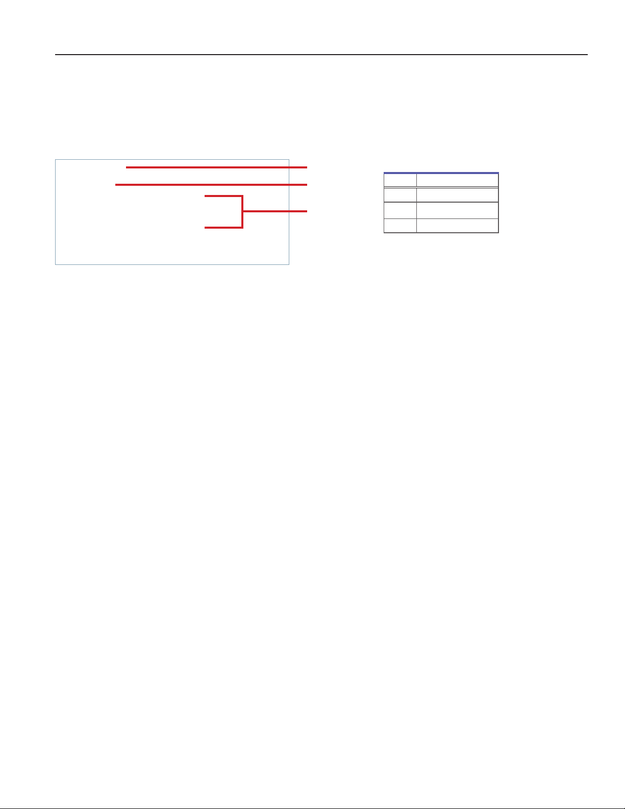
1.7 Product Labels
Thisinformationappearsontheproductspecicationlabel,locatedontherearofthefreezertowardthebottomleftcorner.
The model also appears on a label located in the chamber on the upper right-side wall.
Note
Informationcontainedinthisspecicationlabelvariesdependingonthemodelandpowerrequirements.
Sample Product Specication label.
Label Description
A Model (REF)
B Serial number
C Power requirements
C
B
A

Helmer Scientic i.Series® and Horizon Series™Freezer - Undercounter Service and Maintenance Manual
360417/A 7
i.Series Information
2 InstallationandConguration
2.1 Location Requirements
Keep all ventilation openings in the enclosure or, in the structure for building-in, clear of obstruction.
♦ Hasagroundedoutletmeetingtheelectricalrequirementslistedontheproductspecicationlabel.
♦Is clear of direct sunlight, high temperature sources, heating vents, and air conditioning vents.
♦Has a minimum of 3” (76 mm) of space behind the freezer for clearance and feature access.
♦ MeetsspeciedlimitsforambienttemperatureandrelativehumidityasstatedintheProductSpecicationssectionof
the Instructions for Use manual.
2.2 Placement and Leveling
NOTICE
• To prevent tipping, ensure the casters (if installed) are unlocked and the door is closed before moving the freezer.
• Use of leveling feet or casters is required.
• Do not sit, lean, push or place heavy objects on top surface.
• Do not lean on or push down on an open door or extended drawers.
• To avoid damaging refrigerant tubing or risking refrigerant leak, use caution when moving or operating the unit.
1. Ensure the door is secured and casters (if installed) are unlocked.
2. Move the freezer into place. Lock the casters if installed.
3. Ensure the freezer is level.
Note
Helmerrecommendstheuseoflevelingfeetandwallandoorbrackets(PN400472-2)forstabilization.ContactHelmer
Technical Service for parts and instruction.
2.3 Stacked Undercounter Units
NOTICE
• Forstackedconguration,bothunitsmusthavelevelingfeetinstalled.
• Back brace bars and front stabilizing brackets must be installed (Blue - PN 400821-1; Stainless Steel - PN 400821-2).
• When stacking units, place the heavier unit on the bottom.
• Do not open multiple loaded drawers at the same time.
• Do not lean on or push down on an open door or extended drawers.
Contact Helmer or your distributor for more information regarding the stacking kit and methods to secure both units to the wall
and/oroor.

Helmer Scientic i.Series® and Horizon Series™Freezer - Undercounter Service and Maintenance Manual
360417/A 8
2.4 Connect Back-Up Power
The monitoring system and chart recorder each have a back-up battery system enabling a period of continuous operation if power
is lost.
Battery life varies by manufacturer, voltage level remaining as well as whether optional Access Control is installed. Providing full
power is available, Access Control is not installed, and no battery-related alarms are active, back-up power for the monitoring
system is available for up to 20 hours (the Low Battery alarm will activate after approximately 18 hours of battery use). Providing
full power is available, back-up power for the monitoring system and optional Access Control system is available for up to
2.5 hours.
Before installing or replacing batteries, switch AC power and back-up battery switches OFF. Disconnect the freezer from
AC power.
Notes
• The optional Access Control system uses the monitoring system back-up battery for back-up power in the event of
power failure.
• The monitoring system will start on back-up battery power alone. If the freezer was not previously connected to AC
power and the back-up battery is switched on, the monitoring system will begin running on back-up battery power.
• If AC power is lost, the monitoring system will automatically disable some features to prolong back-up battery power.
Data collection will continue until back-up battery power is depleted.
The back-up battery is located below the chamber, behind the right side panel. The panel cover must be removed to access
the battery.
Monitoring system back-up battery.
2.5 Prepare for Monitoring
The back-up battery switch is switched OFF for shipping. Switch the back-up battery switch ON to provide the monitoring system
and optional Access Control system with back-up power in the event of AC power failure.
Temperature Probes
Notes
• Temperature probes are fragile; handle with care.
• Failuretolltheprobebottleorkeeptheprobebottlelledtotheappropriatelevelmaycausethechamber
temperature to display higher or lower than the actual temperature.
• Remote probes may also be introduced through the existing port and immersed in existing probe bottle.
• External probes should not be routed into the chamber through the door opening as this may cause issues with the
door seal.
A probe bottle and container of propylene glycol have been provided with this unit. The propylene glycol is mixed with water
to create a solution which, when placed in the probe bottle, simulates the product stored in the freezer. The product simulation
solutiontemperaturereectstheproduct’stemperatureduringnormaloperation.
The probe bottle should contain 4 oz. (120 mL) of product simulation solution (1:1 ratio of water to propylene glycol).
i.Series

Helmer Scientic i.Series® and Horizon Series™Freezer - Undercounter Service and Maintenance Manual
360417/A 9
Probe bottle with probe. Rear access port.
Fill Probe Bottle
1. Remove the probe(s) from the bottle and remove the bottle from the bracket.
2. Removethecapandllwith4oz.(120mL)ofproductsimulationsolution.
3. Replace and secure the cap and place the bottle in the bracket.
4. Replace the probe(s), immersing at least 2” (50 mm) in solution.
Install Additional Probe Through Rear Port
1. Peel back putty to expose the port.
2. Insert the probe through the port into the chamber.
3. Insert the probe into the bottle.
4. Replace putty, ensuring a tight seal.
Chart Recorder (if included)
Note
• If the chart recorder has been operating on battery power, the battery should be replaced to ensure the back-up source
has proper charge.
• For complete information, refer to the Temperature Chart Recorder Operation and Service Manual.
The chart recorder has a back-up battery system, enabling a period of continuous operation if power is lost. Battery life varies
by manufacturer as well as voltage level remaining. Providing full power is available, back-up power for the temperature chart
recorder is available for up to 14 hours.
Prior to use:
Route the chart recorder probe through the rear access port and place in the bottle with the primary monitor probe.
Set up and Operation
Access the chart recorder by pulling the door open.
Install Battery
Connect the leads to the battery to provide back-up power to the chart recorder.
i.Series

Helmer Scientic i.Series® and Horizon Series™Freezer - Undercounter Service and Maintenance Manual
360417/A 10
Install / Replace Chart Paper
Notes
• For accurate temperature reading, ensure the current time is aligned with the time line groove when the chart knob is
fully tightened.
• Contact Helmer Customer Service or your distributor to reorder chart paper.
Chart recorder stylus and time line groove
1. Press and hold the Cbutton.Whenthestylusbeginstomoveleft,releasethebutton.TheLEDashes.
2. When the stylus stops moving, remove the chart knob then move the knob up and away.
3. Place chart paper on the chart recorder.
4. Gently lift the stylus and rotate the paper so the current time line corresponds to the time line groove.
5. Hold the chart paper in place while making sure the chart knob is fully tightened. (Failure to fully tighten the knob can result in paper
slipping and losing time.)
6. Press and hold the C button. When the stylus begins to move right, release the button.
7. Conrmthestylusismarkingonthepaperandstopsatthecorrecttemperature.
8. Calibrate the chart recorder to match the primary temperature if needed and close the recorder door.
External Monitoring Devices
The remote alarm interface is a relay switch with three terminals:
♦Common (COM)
♦Normally Open (NO)
♦Normally Closed (NC)
Terminals are dry contacts and do not supply voltage. The interface circuit is either normally open or normally closed, depending on
terminals used.
Requirements for your alarm system determine which alarm wires must connect to terminals.
• Theinterfaceontheremotealarmmonitoringsystemisintendedforconnectiontotheenduser’scentralalarm
system(s) using normally-open or normally-closed dry contacts.
• Ifanexternalpowersupplyexceeding33V(RMS)or70V(DC)isconnectedtotheremotealarmmonitoringsystem’scircuit,
the remote alarm will not function properly and may cause damage to the control board or result in injury to the user.
The terminals on the remote alarm interface have the following maximum load capacity:
♦115V or 230V: 1 A at 33 V (AC) RMS or 30 V (DC)
Connect to Remote Alarm Interface
1. On the back of the freezer, locate the remote alarm terminals.
2. Connect the remote alarm wires to the appropriate terminals, according to the requirements for your alarm system.
3. Use a cable tie to relieve strain on the alarm wires (as necessary).
i.Series

Helmer Scientic i.Series® and Horizon Series™Freezer - Undercounter Service and Maintenance Manual
360417/A 11
2.6 CongureStorage
Notes
• Before moving storage components, protect stored items in freezer from extended exposure to adverse temperature.
• Before moving drawers or shelves, ensure they are completely empty for safe lifting.
• Maximum drawer or shelf load is 100 lbs (46 kg).
Product Loading Guidelines
Note
Productsstackedagainstthebackwallmayobstructairowandaectperformanceoftheunit.
When loading your freezer, take care to observe the following guidelines:
♦Never load the freezer beyond capacity.
♦Always store items within shelves or drawers.
♦ Temperatureuniformityismaintainedbyaircirculation,whichcouldbeimpedediftheunitisoverlled,particularlyat
the top or back. Ensure a minimum of 2” (50 mm) clearance is provided below the fan.
Drawers
Remove Drawer
1. Pull the drawer out until it stops.
2. Liftthefrontofthedrawerothefrontrollersontheslide.
3. With the front of the drawer slightly lifted, pull the drawer all the way forward. The rear drawer rollers should be touching
the front slide rollers.
4. Lift the drawer to free from the slides.
Install Drawer
1. Align the rear rollers on the drawer with the opening just behind the front slide rollers.
2. Place the rear drawer rollers on the slides and gently push the drawer into the chamber until it stops.
3. Pull the drawer out until it stops to check for smooth operation.
Move Drawer Slides
1. Using a screwdriver, remove the bracket retainers.
2. Tap the brackets upward to disengage from standards.
3. Remove the slides from the standards.
4. Insert the slides into the standard at the appropriate height.
5. Tap the brackets downward to engage with standards.
6. Using a screwdriver, install the bracket retainers.
i.Series

Helmer Scientic i.Series® and Horizon Series™Freezer - Undercounter Service and Maintenance Manual
360417/A 12
Shelves
Remove Shelf
1. With one hand, lift the front edge of the shelf from the front brackets.
2. With the other hand, reach under the shelf and bump the rear edge of the shelf upward to disengage rear brackets.
Install Shelf
1. Insert the shelf into chamber, placing it on the brackets.
2. Gently bump the rear edge of the shelf downward to engage with brackets.
3. Pulling the shelf forward gently; the shelf should not disengage from the rear brackets
Move Shelf Brackets
1. Using a screwdriver, remove the bracket retainers.
2. Tap the brackets upward to disengage from standards.
3. Remove the brackets from the standards.
4. Insert the brackets into the standard at the appropriate height.
5. Tap the brackets downward to engage with standards.
6. Using a screwdriver, install the bracket retainers.
2.7 Optional Adapter Kits for Medication Dispensing Locks
Contact Helmer Technical Service or your distributor for service documentation pertaining to medication dispensing locks.
i.Series

Helmer Scientic i.Series® and Horizon Series™Freezer - Undercounter Service and Maintenance Manual
360417/A 13
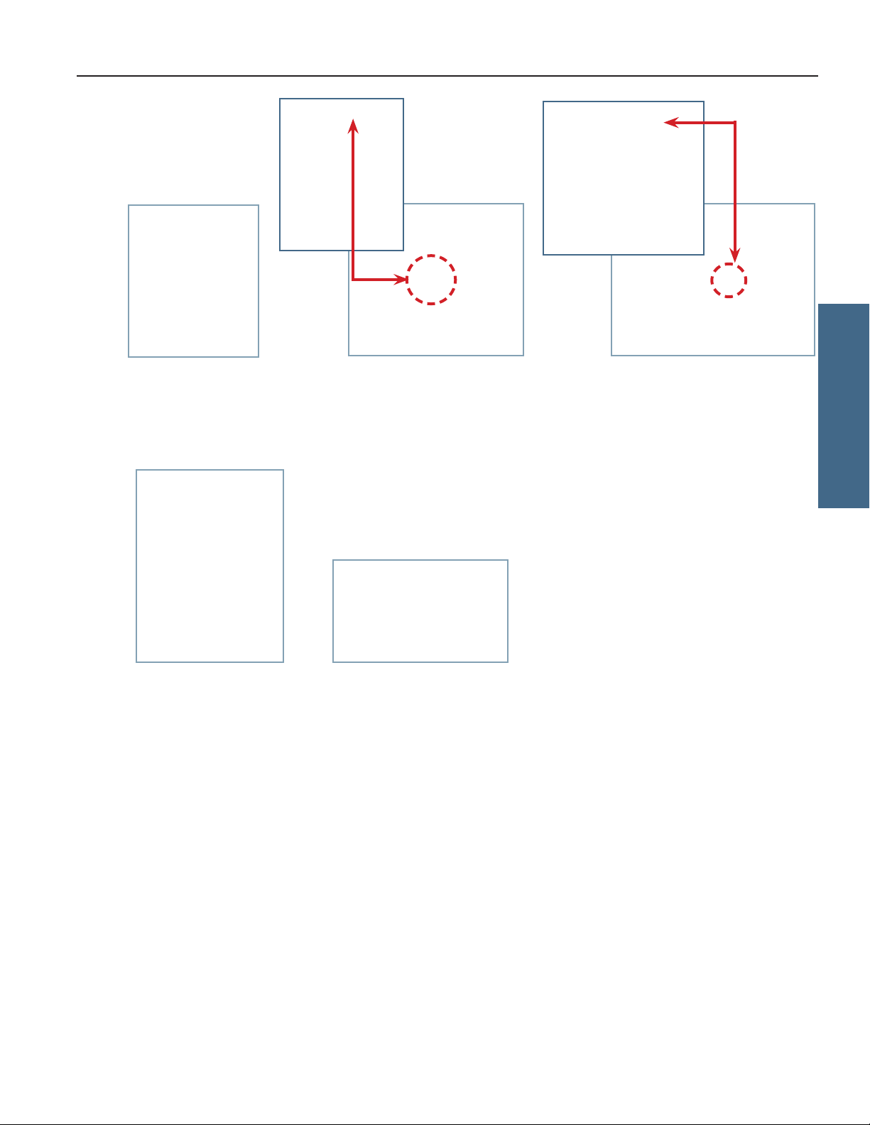
2.8 Reverse Door Hinges and Handle
Notes
• The following instructions apply to reversing a right-hinged door to a left-hinged door. Some steps will need to be
reversed if changing from left-hinged to right-hinged.
• Door hinges and handle cannot be reversed on units equipped with Access Control.
• Unitmustbeontheoororanelevatedworksurfacewithadequatespacetoplacethedoorface-downinfrontoftheunit.
• To prevent personal injury and/or damage to the door, Helmer recommends two people for this procedure.
Remove Door and Hinges
1. Press and release the door to open the access panel. Switch the AC power switch to OFF, and switch the back-up
battery switch to OFF.
2. Disconnect the AC power cord from the power receptacle.
3. Remove the six screws securing the front access panel to the unit and carefully place it in front of the freezer ensuring
there is no strain on the wiring.
4. Remove the plug from the access panel on the handle-side of the unit. Remove the grommet from the hole on the
hinged-side of the unit and slide the braided sleeve out of the slot.
5. Remove the four screws securing the door handle assembly to the door and set the assembly aside.
6. Remove the two screws attaching the strike plate to the unit and set aside.
1
3
4
56
i.Series

Helmer Scientic i.Series® and Horizon Series™Freezer - Undercounter Service and Maintenance Manual
360417/A 14
7. With the door shut, remove the cover plates from both hinges.
8. Usinga3/8"wrenchandaatheadscrewdriver,loosenthehexnutoneachhingespring.Thehingepinwilldropfrom
below allowing the spring to be removed. Set the hinge pins and springs aside.
9. Carefullyliftthedoorupandothehingesandplaceface-downinfrontoftheunittakingcarenottodamagethe
display assembly and ensuring there is no strain on cables running from the cabinet to the door.
10. Using a #2 Phillips screwdriver, remove the two screws attaching upper and lower hinges to the door and set aside.
11. Using a #2 Phillips screwdriver, remove the three screws securing the upper and lower hinges to the unit and set aside.
12. Remove the plastic cam insert from each hinge assembly noting the direction of the dwell (facing left), and set aside.
Reroute Communication Cables
1. Remove the right-side panel using a #2 Phillips head screwdriver to remove the top and bottom center screws and
loosening the remaining screws in each corner of the panel. Slide the panel upward to disengage the four screws from
the keyhole openings and remove the panel.
2. Locate the control board and disconnect the display power and communication cables.
8b
8a
7
10 11
12
12
i.Series
Helmer Scientic i.Series® and Horizon Series™Freezer - Undercounter Service and Maintenance Manual
360417/A 15
3. Remove the remaining screws from the door assembly.
4. Using a punch or J-hook tool along bottom edge of the door, lift the inner door frame out of the outer door frame.
5. Remove the plug from the door on the handle-side and set aside.
6. Pull the grommet out of the hole in the door on the hinged-side and slide the braided sleeve out of the slot.
7. Cut the zip tie securing the door switch wires.
8. Secure the door switch wires along with the display power and communication cables to the zip tie holder using a zip tie.
9. Reroute the display power and communication cables along the inside edge of the door and through the slot in the
corner opposite their initial location.
10. Tape the cables to the inside of the door ensuring any excess cable is on the outside of the door.
11. Cut the zip ties securing the braided sleeve, and slide the sleeve and grommets along the cables toward the door.
12. Slip the braided sleeve through the slot in the door and insert the door-side grommet into the hole in the door.
13. Secure the braided sleeve around the cables using the zip ties at each end to prevent the sleeve from sliding.
456
10 13
i.Series

Helmer Scientic i.Series® and Horizon Series™Freezer - Undercounter Service and Maintenance Manual
360417/A 16
Reassemble Door / Reverse Hinges
1. Reinstalltheinnerdoorpanelandsecurewiththescrewsintheholesoppositetheoriginalconguration.
2. Rotate the plastic cam insert so the dwell is now facing the opposite direction (right), and insert in the hinge assembly.
3. Reinstall the door hinge plates onto the opposite side of the door frame by aligning the holes in the hinge plates with
the holes in the door frame and hand-threading the two long screws in each hinge (leave screws slightly loose).
4. Reinstall the corresponding hinge plates to the unit by hand-threading the three short screws through the hinge and
into the cabinet.
5. Align the upper hinge cams on the door with the lower hinge cams on the freezer as you carefully reattach the door to
the unit.
6. Level the door and tighten all screws securing the hinges to the unit.
7. Slide the braided sleeve through the slot in the front access panel allowing approximately 3” (76 mm) of slack between the
door and the cabinet so the door can open and close without straining cables. Install the grommet in the access panel.
8. Attach the door handle on the opposite side of the door with four screws.
9. Attach the strike plate to the opposite side of the unit with two screws. Test the locking mechanism to ensure
proper functionality.
10. With the door closed, reinstall the hinge pin and spring in the upper hinge. Secure with the hex nut using a 3/8" wrench
andatheadscrewdriver(hex nut should be tightened until it stops turning). Repeat the process for lower hinge.
11. Replace the hinge cover plates.
12. Reconnect the display power and communication cables to the control board.
13. Reinstall the right-side access panel by engaging the four screws in unit base with the keyhole openings in the panel.
Insert the top and bottom center screws and tighten all screws using a #2 Phillips screwdriver.
14. Reinstall the front access panel and secure with six screws.
15. Plug the power cord into the power receptacle. Switch the AC power switch ON. Switch the back-up battery switch ON.
16. Verify the door is level, hinges operate smoothly and the door seals tightly.
17. Allow the temperature to stabilize at the setpoint before moving inventory back into the unit.
Dwell will face right when
unit is left-hinged.
i.Series
2

Helmer Scientic i.Series® and Horizon Series™Freezer - Undercounter Service and Maintenance Manual
360417/A 17
3 Controls
i.Series models are equipped with the i.C3monitoring and control system. The i.C3system combines temperature control and
monitoring into a single user interface.
Note
Please refer to the i.C3User Guide for complete information regarding the i.C3User Interface.
3.1 Home Screen and Screensaver
The Home Screen is the default screen and is displayed when:
♦The Home icon is touched from any other screen.
♦There is no interaction for two minutes on any screen other than those used to enter a password.
Home Screen Screensaver
3.2 Home Screen Functions
Note
Refer to the i.C³ User Guide for options available on all i.C³ screens.
♦View current interior cabinet temperature readings
♦View current system time and date
♦ Accessanyofthevehomescreenapplications(touchi.C³ APPS for additional applications)
♦View information about current alarm events
♦View whether the monitoring system is running on battery power
♦Mute audible alarms
♦View a graph of the chamber temperature
♦View unit ID
♦Shortcut to Event Log
3.3 Alarm Reference
If an alarm condition is met, an alarm activates. Some alarms are visual only; others are visual and audible. Some alarms are sent
through the remote alarm interface. The table below indicates if an alarm is audible (A), visual (V), or sent through the remote
alarm interface (R).
Table 2. i.Series Alarm Reference
Alarm Alarm Type Alarm Alarm Type
High Temperature A, V, R Low Battery V
Low Temperature A, V, R No Battery A, V, R
Compressor Temperature A, V, R Probe Failure A, V, R
Door Open (Time) A, V, R Communication Failure A, V, R
Power Failure A, V, R
i.Series

Helmer Scientic i.Series® and Horizon Series™Freezer - Undercounter Service and Maintenance Manual
360417/A 18
3.4 Settings
>
Through the i.C³ monitoring and control system, current settings may be viewed and changed. To view settings, touch i.C³ APPS,
Settings. Use a touch-drag motion to scroll up or down to select the desired setting.
Settings screens
Notes
• IftheSettingsscreenispasswordprotected,entertheappropriatepassword.Ifviewingsettingsforthersttime,enterthe
factory default password of “1234”.
• Default values for general settings, alarm settings, and display settings are available in the i.C³ User Guide.
• Changingtemperaturesettingsaectsoperationofthefreezer.Donotchangesettingsunlessinstructedin
product documentation or by Helmer Technical Service.
Thei.C³temperaturemonitorandcontrollerisprogrammedatthefactory.Tochangeasetting,rstentertheSettingsscreen,then
select the setting. The method for accessing the Settings mode for each setting varies.
Device Control Settings
Device control settings are programmed at the factory. Setpoints can be viewed and changed through the i.C³ monitoring and control
system. To view temperature setpoints, touch i.C³ APPS, Settings, Device Control Settings.
Device Control Settings screen.
Table 3. Setpoints
Setting Initial Factory Value
Temperature Setpoint -30.0 °C
Upper Rail 0.7 °C
Lower Rail -0.7 °C
Delay on Start-Up 2 minutes
Speed During Probe Error 50%
i.Series

Helmer Scientic i.Series® and Horizon Series™Freezer - Undercounter Service and Maintenance Manual
360417/A 19
Temperature Setpoint
The setpoint is the temperature at which the freezer operates. The factory default setting for the primary monitor probe is
-30.0°C.
Notes
• IftheSettingsscreenispasswordprotectedentertheappropriatepassword.Ifviewingsettingsforthersttime,enter
the factory default password of “1234”.
• Temperature Setpoint can be adjusted through the main Settings screen and Device Control Settings screen.
• Change the setpoint if your organization requires a chamber temperature other than -30.0 °C.
Change Temperature Setpoint
1. Touch i.C³ APPS, Settings.
2. Enter the Settings password.
3. Touch the minus (–) or plus (+) on the Temperature Setpoint spin box to select the desired value.
Upper Rail
Upper rail is the maximum control temperature at which the compressor will turn on.
Lower Rail
Lowerrailistheminimumcontroltemperatureatwhichthecompressorwillturno.
Delay on Start-Up
Compressorstartupisdelayedtoallowthei.C³monitoringandcontrolsystemtostartrst.
Speed During Probe Error
The compressor will run as a percent of maximum if both the monitor and control probe fail.
NOTICE
Upper Rail, Lower Rail, Delay on Start-up and Speed During Probe Error are factory-preset and should not be changed
unless directed by Helmer Technical Service.
i.Series
Other manuals for i Series
2
This manual suits for next models
5
Table of contents
Other Helmer Scientific Freezer manuals

Helmer Scientific
Helmer Scientific i.Series User manual

Helmer Scientific
Helmer Scientific i.Series Installation and user guide

Helmer Scientific
Helmer Scientific i.Series User manual

Helmer Scientific
Helmer Scientific iLF120 Installation and user guide

Helmer Scientific
Helmer Scientific i.Series User manual


