Helmer Scientific i.Series User manual

HELMER SCIENTIFIC
14400 Bergen Boulevard
Noblesville, IN 46060 USA
PH +1.317.773.9073
FAX +1.317.773.9082
USA and Canada 800.743.5637
0086
ISO 13485:2003 CERTIFIED
360137-D/D
Model Group i.Series Horizon Series
Plasma Storage iPF105 (Version D) HPF105 (Version D)
Laboratory iLF105 (Version D) HLF105 (Version D)
Undercounter Freezer Operation Manual
i.Series®and Horizon Series™

360137-D/D i
Document History
Revision Date CO Supersession Revision Description
A 23 JAN 2013 8187 n/a Initial release.
B 04 DEC 2013* 8953 B supersedes A
► Removed all references to mechanical Access Control.
► Added references to magnetic Access Control.
► Corrected shipping location of monitoring system backup
battery for Horizon Series.
C 22 MAY 2014* 9497 C supersedes B
► Added information to operating standards from technical
audit.
► Revised specications for remote alarm contacts.
D 16 MAR 2015* 10319 D supersedes C
► Updated instruction in Section III, Items 9.2 through 9.7.1 to
reect use of monitor and control interface with new Min/Max
temperature recording feature.
► Added Document Updates, to Document History page.
► Added Condential / Proprietary Notice, Section I, Item 1.4
and Disclaimer, Section I, Item 1.5
► Moved Maintenance Schedule, i.Series®Components and
Horizon Series™ Components to Appendices A, B and C.
* Date submitted for Change Order review. Actual release date may vary.
Document Updates
The document is furnished for information use only, is subject to change without notice and should not be construed as a
commitment by Helmer Scientic. Helmer Scientic assumes no responsibility or liability for any errors or inaccuracies that
may appear in the informational content contained in this material. For the purpose of clarity, Helmer Scientic considers
only the most recent revision of this document to be valid.

360137-D/D ii
Section I: General Information ........................................4
1 About this Manual .......................................................... 4
1.1 Intended Audience. . . . . . . . . . . . . . . . . . . . . . . . . . . . . . . . . . . . . . . . . . . . . . . . . . . . . . . . . . . . . . . . . . . . . . 4
1.2 Model References ......................................................................4
1.3 Copyright and Trademark ................................................................4
1.4 Condential / Proprietary Notices ..........................................................4
1.5 Disclaimer ............................................................................4
2 Safety .................................................................... 5
2.1 Labels ...............................................................................5
2.2 Avoiding Injury.........................................................................5
3 General Recommendations. . . . . . . . . . . . . . . . . . . . . . . . . . . . . . . . . . . . . . . . . . . . . . . . . . . 5
3.1 Intended Use..........................................................................5
3.2 General Use ..........................................................................5
3.3 Initial Loading .........................................................................5
4 Operating Standards ........................................................ 6
4.1 Stacked Undercounter Units ..............................................................6
4.2 Electrical Specications. . . . . . . . . . . . . . . . . . . . . . . . . . . . . . . . . . . . . . . . . . . . . . . . . . . . . . . . . . . . . . . . . . 6
4.3 Dimensions ...........................................................................7
4.3.1 Weight ........................................................................7
5 Regulatory Compliance...................................................... 8
6 Installation ................................................................ 9
6.1 Location Requirements ..................................................................9
6.1.1 Placement .....................................................................9
6.2 Temperature Probes ....................................................................9
6.3 Chart Recorder .......................................................................10
6.3.1 Install and Change Chart Paper ....................................................10
Section II: i.Series®Models..........................................11
7 Operation ................................................................ 11
7.1 Initial Start Up ........................................................................11
7.2 Change Temperature Setpoint ...........................................................11
7.3 Set Alarm Parameters ..................................................................12
7.4 Normal Operation .....................................................................12
7.5 Active Alarms.........................................................................12
7.6 Mute and Disable Active Alarms ..........................................................13
7.7 Access Control (Optional) ...............................................................13
7.7.1 Setup ........................................................................13
7.7.2 Open Freezer with Access Control..................................................14
Contents

360137-D/D iii
8 i.C³®Icon Reference Guide .................................................. 14
Section III: Horizon Series™ Models ..................................15
9 Operation ................................................................ 15
9.1 Initial Start Up ........................................................................15
9.2 Monitor and Control interface ............................................................15
9.3 Display Minimum and Maximum Monitor Temperature Recordings ...............................15
9.4 Change Freezer Temperature Setpoint.....................................................16
9.5 Table of Parameters ...................................................................16
9.5.1 Setting Parameter Values.........................................................17
9.5.2 Set Temperature Units ...........................................................17
9.6 Temperature Calibration Offsets ..........................................................17
9.6.1 Monitor Offset..................................................................17
9.6.2 Control Sensor Offset............................................................17
9.6.3 Hysteresis.....................................................................17
9.7 Temperature Alarm Setpoints ............................................................18
9.7.1 Change a Temperature Alarm Setpoint ..............................................18
9.8 Active Alarms.........................................................................18
9.8.1 Mute and Disable Audible Alarms...................................................18
9.9 Access Control (Optional) ...............................................................19
9.9.1 Setup ........................................................................19
9.9.2 Add User Code.................................................................19
9.9.3 Delete User Code...............................................................19
9.9.4 Open Freezer with Access Control..................................................19
Appendix A: Maintenance Schedule..................................20
Appendix B: i.Series®Components ..................................21
Appendix C: Horizon Series™ Components ...........................24

360137-D/D 4
General Information
Section I: General Information
1 About this Manual
1.1 Intended Audience
This manual is intended for use by end users of the freezer and authorized service technicians.
1.2 Model References
Generic references are used throughout this manual to group models that contain similar features. For
example, “105 models” refers to all models of that size (iPF105, HPF105, iLF105, HLF105). This manual
covers all undercounter freezers, which may be identied singly, by their size, or by their respective
“Series.”
1.3 Copyright and Trademark
Helmer®, i.Series®, i.C³®, Horizon Series™, and Rel.i™ are registered trademarks or trademarks of
Helmer, Inc. in the United States of America. Copyright © 2015 Helmer, Inc. All other trademarks and
registered trademarks are the property of their respective owners.
Helmer, Inc., doing business as (DBA) Helmer Scientic and Helmer.
1.4 Condential/ProprietaryNotices
Use of any portion(s) of this document to copy, translate, disassemble or decompile, or create or attempt
to create by reverse engineering or otherwise the information from Helmer Scientic products is expressly
prohibited.
1.5 Disclaimer
This manual is intended as a guide to provide the operator with necessary instructions on the proper use
and maintenance of certain Helmer Scientic products.
Any failure to follow the instructions as described could result in impaired product function, injury to the
operator or others, or void applicable product warranties. Helmer Scientic accepts no responsibility for
liability resulting from improper use or maintenance of its products.
The screenshots and component images appearing in this guide are provided for illustrative purposes
only, and may vary slightly from the actual software screens and/or product components.

360137-D/D 5
General Information
2 Safety
Includes general safety information for freezer operation.
2.1 Labels
Caution: Risk of damage
to equipment or danger to
operator
Caution: Unlock all casters
Caution: Hot surface Earth / ground terminal
Caution: Shock/electrical
hazard
Protective earth / ground
terminal
Warning: Hazardous situation
which could result in injury
2.2 Avoiding Injury
► Review safety instructions before installing, using, or maintaining the equipment.
► Do not open multiple, loaded drawers or baskets at the same time.
► Before moving unit, ensure casters are unlocked and free of debris.
► Never physically restrict any moving component.
► Avoid removing electrical service panels and access panels unless so instructed.
► Use manufacturer supplied power cords only.
CAUTION Decontaminate parts prior to sending for service or repair. Contact Helmer or your
distributor for decontamination instructions and a Return Authorization Number.
3 General Recommendations
3.1 Intended Use
Helmer freezers are intended for the storage of blood products and other medical and scientic products.
3.2 General Use
Allow freezer to come to room temperature before switching power on.
During initial startup, high temperature alarm may sound while freezer reaches operating temperature.
3.3 Initial Loading
Allow the freezer to reach room temperature before powering on. Allow chamber temperature to stabilize
at the setpoint before storing product.
NOTE Do not overload top drawer, basket, or shelf such that airow from the unit cooler is
obstructed.

360137-D/D 6
General Information
4 Operating Standards
These units are designed to operate under the following environmental conditions:
► Indoor use only
► Altitude (maximum): 2000 m
► Ambient temperature range: 15 °C to 32 °C
► Relative humidity (maximum for ambient temperature): 80% for temperatures up to 31 °C, decreasing
linearly to 50% at 40 °C
► Temperature control range: -15 °C to -30 °C
► Overvoltage category: II
► Pollution degree: 2
► Mains supply voltage: ±10% of nominal voltage
4.1 Stacked Undercounter Units
CAUTION ► For a stacked conguration, both units must have leveling feet installed.
► The back brace bars and front stabilizing brackets must be installed [PN 400821-1
(blue) or 400821-2 (stainless steel)].
► When stacking a refrigerator and freezer (104 and/or 105 models), place the heavier
unit on the bottom.
► Do not open multiple, loaded drawers or baskets at the same time.
Call Helmer or your distributor for more information on the stacking kit, and for methods to secure both
units to the wall and/or the oor.
4.2 ElectricalSpecications
Refer to specication label for voltage and power consumption requirements. Voltage tolerance is ±10%.
Power consumption is measured in full load Amperes.
Input Voltage PowerConsumption
115 V, 60 Hz 5.75 A
230 V, 50 Hz 2.8 A
230 V, 60 Hz 3.1 A
Circuit breakers are used only on 230 V models. The rating for 230 V models is 6 A (quantity 2).
The terminals on the remote alarm interface have the following maximum load capacity:
► i.Series: 0.5 A at 30 V (RMS); 1.0 A at 24 V (DC)
► Horizon Series: 0.25 A at 30 V (RMS); 0.25 A at 60 V (DC)
CAUTION ► The interface on the remote alarm monitoring system is intended for connection to
the end user’s central alarm system(s) that uses normally-open or normally-closed
dry contacts.
► If an external power supply exceeding 30 V (RMS) or 60 V (DC) is connected to the
remote alarm monitoring system’s circuit, the remote alarm will not function properly;
may be damaged; or may result in injury to the user.

360137-D/D 7
General Information
4.3 Dimensions
4.3.1 Weight
NOTE The weight may vary slightly depending on installed options. Weights provided are for
standard congurations as shown.
Model
Family Conguration Weight
iPF 2 drawers 221 lbs
101 kg
iLF 2 shelves 215 lbs
98 kg
HPF 2 drawers 215 lbs
98 kg
HLF 2 shelves 209 lbs
95 kg
NOTE ► Plasma storage models (iPF) feature drawers as the standard storage conguration.
Laboratory/ pharmacy models (iLF) feature shelves as the standard storage
conguration. Any combination of drawers, baskets, and shelves may be installed.
► Maximum load per drawer is 100 lbs / 46 kg
4.3.2 Size
All dimensions are for the overall exterior and include items that protrude from the main unit.
Width 24”
610 mm
Height(withoutcasters
or leveling feet)
33.5”
864 mm
Depth 28.5”
724 mm
NOTE ► With casters, height is approximately 35.5” (915 mm).
► With the leveling feet fully engaged (minimum height), height is approximately 34”
(889 mm).
► The maximum height leveling feet may add is approximately 2” (51 mm).
► Add 0.375” (10 mm) to the width for optional Access Control.

360137-D/D 8
General Information
5 Regulatory Compliance
This device complies with the requirements of directive 93/42/EEC concerning
Medical Devices, as amended by 2007/47/EC.
0086
Sound level is less than 70 dB(A).
EC REP Emergo Europe
Molenstraat 15
2513 BH
The Hague, Netherlands
WEEE Compliance
The WEEE (waste electrical and electronic equipment) symbol (right) indicates
compliance with European Union Directive WEEE 2002/96/EC and
applicable provisions. The directive sets requirements for the labeling and
disposal of certain products in affected countries.
When disposing of this product in countries affected by this directive:
► Do not dispose of this product as unsorted municipal waste.
► Collect this product separately.
► Use the collection and return systems available locally.
For more information on the return, recovery, or recycling of this product, contact your local distributor.

360137-D/D 9
General Information
6 Installation
6.1 Location Requirements
► Has a grounded outlet meeting national electric code (NEC) and local electrical requirements.
► Is clear of direct sunlight, high temperature sources, heating vents, and air conditioning vents.
► Has a minimum of 3” (76 mm) of space behind the freezer for clearance and feature access.
► Meets the limits specied for ambient temperature and relative humidity.
6.1.1 Placement
WARNING To prevent tipping:
► ensure the casters (if installed) are unlocked and the door is closed before moving
the freezer.
► do not sit, lean, push or place heavy objects on upper door ledge.
1 If casters are installed, install strain relief as shown below to prevent accidental disconnection.
2 Ensure door is closed and casters (if installed) are unlocked.
3 Move freezer into place. Lock casters if installed.
4 Ensure freezer is level.
Strain relief for power cord (for freezers with casters installed)
NOTE Helmer recommends the use of leveling feet (unless casters are installed) and wall and
oor brackets (PN 400472-2) for stabilization. Contact Helmer Technical Service for parts
and instruction.
6.2 TemperatureProbes
For each probe bottle, use:
► 4 oz. (120 mL) of product simulation solution (1:1 ratio of water to propylene glycol or equivalent low-
temperature uid).

360137-D/D 10
General Information
6.3 Chart Recorder
A B F
C
D
E
Chart recorder with paper and battery installed.
Label Description Function
ALeft and Right Arrow
buttons
Adjust settings and stylus position
B LED Indicates status of chart recorder in operating mode, or selected
temperature range in paper change mode
C Chart change button Adjust position of stylus when changing chart paper, or run a test pattern
D Stylus Mark temperature line on paper
E Reset button Restart chart recorder
F Backup battery Provides power during AC power failure. Connect prior to use.
6.3.1 InstallandChangeChartPaper
1 Press and hold C button. When stylus begins to move left, release button. The LED ashes to
indicate current temperature range.
2 When stylus stops moving, remove chart knob then move knob up and away from chart paper.
3 Place new chart paper on chart recorder.
4 Gently lift stylus and rotate paper so current time line corresponds to time line groove.
5 Hold chart paper and reinstall chart knob.
NOTE For accurate temperature reading, ensure that current time is aligned with time line
groove when chart knob is tightened.
6 Conrm the temperature range is set to the correct value.
7 Press and hold C button. When the stylus begins to move right, release the button.
8 Conrm the stylus is marking the temperature correctly.
360137-D/D 11
i.Series® Models
Section II: i.Series®Models
7 Operation
7.1 Initial Start Up
1 Plug the power cord into a grounded outlet that meets the electrical requirements on the product
specication label.
2 Switch AC ON/OFF switch ON.
3 Switch backup battery switch ON.
NOTE ► For models equipped with the optional Access Control, the backup battery is switched
on with a key switch.
► The i.C³ monitoring and control system will take approximately two minutes to boot
up.
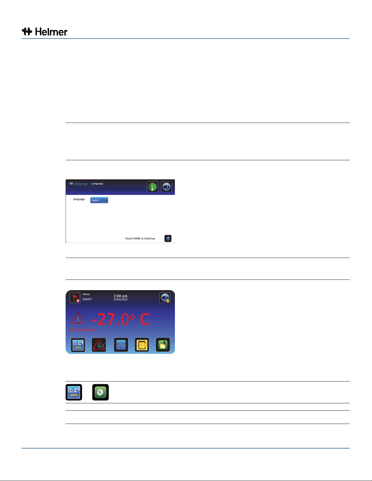
4 Select language.
NOTE Active alarms are displayed on the Home screen. If an alarm condition other than High
Temperature occurs, refer to the service manual for troubleshooting.
5 If an alarm sounds, temporarily mute the alarm by touching the Mute button.
7.2 Change Temperature Setpoint
>
Touch + or – on spin box to change value.
NOTE Default setpoint is -30.0 °C

360137-D/D 12
i.Series® Models
7.3 SetAlarmParameters
> > Alarm Settings
Control the conditions and timing of alarm condition indicators
displayed on the i.C³ Home screen. Touch +or – on spin box to set
each parameter.
7.4 NormalOperation
The i.C³ Home screen displays temperature and alarm information, and provides icons for reaching other
functions of the i.C³.
Home screen Home screensaver (touch to return to Home screen)
7.5 Active Alarms
Home with no alarms. Home with active alarm.
Alarm Description
High Temperature Chamber temperature reading is above high temperature alarm setpoint
Low Temperature Chamber temperature reading is below low temperature alarm setpoint
Low Battery Rechargeable battery voltage is low
Power Failure Power to unit has been disrupted
Probe Failure Probe not functioning properly
Door Open Door is open beyond user-specied duration
Compressor
Temperature Compressor temperature reading is above high temperature alarm setpoint
Communication
Failure Messages
1, 2, 3
1 Communication lost between i.C³ display board and control board
2 Communication lost between i.C³ display board and internal system memory
3 Corrupt database
360137-D/D 13
i.Series® Models
7.6 Mute and Disable Active Alarms
Audible alarms may be muted by touching the Mute button to set delay.
:15
Unmuted Muted
7.7 Access Control (Optional)
Allows user-specic secure access to the freezer.
NOTE ► During a power failure, the backup battery provides power to the monitoring system
and the power failure alarm. If the backup battery is not functioning, the power failure
alarm will not be activated.
► During a power failure, the backup battery continues to provide power to the optional
Access Control lock (if equipped). If the backup battery is not functioning, the
optional Access Control lock will not secure the door.
► During a power failure, the optional Access Control lock will remain locked until
battery power is depleted or until the backup battery key switch is switched OFF.
► Switching the backup battery key switch OFF will disable the monitoring system.
► During a power failure, switch the battery backup switch OFF and use the mechanical
door key to provide secure storage for freezer contents.
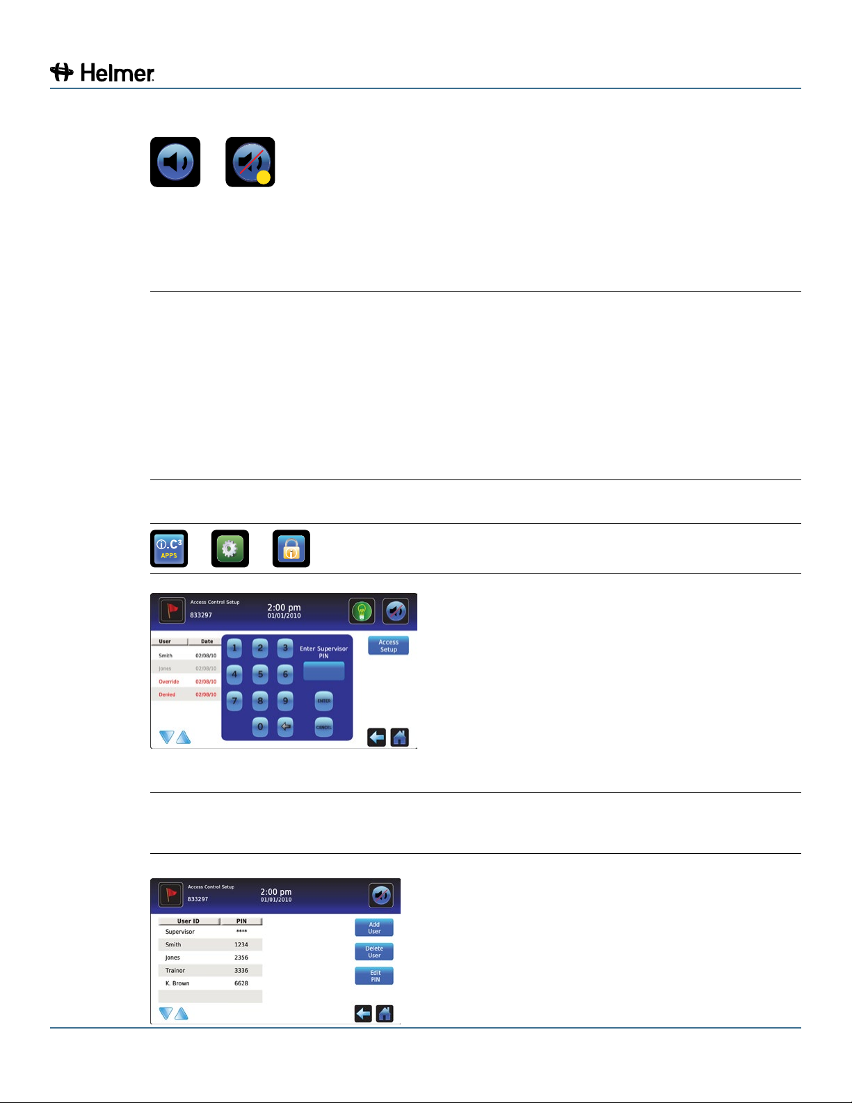
7.7.1 Setup
> > > Access Setup
Congure and manage use-specic accounts to allow
controlled access to the freezer.
► Enter the supervisor PIN to set up Access Control
► Initial factory supervisor PIN = 5625
NOTE The supervisor PIN can not be deleted, and should be changed to prevent unauthorized
user ID setup. The supervisor PIN does not allow access to the unit. At least one user
ID must be set up to gain access to the unit.

360137-D/D 14
i.Series® Models
7.7.2 OpenFreezerwithAccessControl
► Enter a valid PIN using the keypad.
8 i.C³®Icon Reference Guide
Home Download Scroll Arrows
Event Log Upload Defrost Cycle
Settings Temperature
Graph Defrost Log
i.C³ Applications Information Log Access Control
Back Arrow Compressor Log Access Control
Log
Alarm Conditions Icon Transfer Contact Helmer
Alarm Test Display
Brightness Battery Power
Mute

360137-D/D 15
Horizon Series™ Models
Section III: Horizon Series™ Models
9 Operation
9.1 Initial Start Up
1 Plug the power cord into a grounded outlet that meets the electrical requirements on the product
specication label.
2 Switch AC ON/OFF switch ON.
3 Remove the 9 V battery from the literature box and install it.
NOTE ► For models equipped with the optional Access Control, switch the backup battery key
switch ON.
► If an alarm condition other than High Temperature occurs, refer to the service manual
for troubleshooting.
4 Press DownArrow (Mute) if high temperature alarm sounds.
9.2 Monitor and Control interface
Horizon Series monitoring and control interface.
9.3 Display Minimum and Maximum Monitor Temperature Recordings
NOTE ► This feature is standard on Horizon Series™ models with serial numbers of 2015494
or higher. Some exceptions may exist. For conrmation on your unit, please contact
Helmer Technical Service.
► Units that do not include the minimum and maximum recording feature will not display
.C or .F when entering the program mode.
The minimum and maximum recording feature allows the user to view a minimum temperature
occurrence and a maximum temperature occurrence within a given period of time. The timer provides a
time reference in which those temperatures occurred.
NOTE The following steps only apply to the monitor probe.
1 View minimum temperature recording.
a Press and hold the DownArrow button for 1 second and listen for a single beep.
b The display will alternate between LO and a valid temperature value ve (5) times followed by a
single beep to indicate exit back to the temperature display.
High and Low
Temp Lamps
LED Display
SEL Button
CONTROL and
MONITOR Lamps
UP and DOWN Arrows
SET Button

360137-D/D 16
Horizon Series™ Models
2 View maximum temperature recording.
a Press and hold the UpArrow button for 1 second and listen for a single beep.
b The display will alternate between HI and a valid temperature value ve (5) times followed by a
single beep to indicate exit back to the temperature display.
3 View recorded temperature timer.
NOTE ► The timer denotes the period of time that has elapsed. It does not display the time at
which a minimum or maximum temperature occurred.
► The maximum period of time the timer can record is 99:59 (99 hours and 59 minutes).
a Press and hold either the Up or DownArrow button for 1 second.
b While the display is ashing the HI or LO value, press and hold the SET button for 1 second.
c The display will alternate ve (5) times between CLr and a value representing the number of
hours and minutes that have elapsed since the last recording (example: 12:47 would represent 12
hours and 47 minutes). A single beep will follow to indicate exit back to temperature display.
4 Clear minimum and maximum temperature recordings.
a Press and hold either the Up or DownArrow button for 1 second.
b While the display is ashing the HI or LO value, press and hold the SET button for 1 second and
listen for a single beep.
c While the display is ashing the elapsed time since last reset, press and hold the SET button
for 2 seconds. CLr will be displayed followed by a series of 3 beeps to indicate exit back to the
temperature display.
NOTE The minimum and maximum temperature and timer will reset when:
► the unit is powered off and battery backup is not engaged, or
► after 99 hours and 59 minutes have elapsed.
9.4 Change Freezer Temperature Setpoint
NOTE Default setpoint is -30.0 °C
1 Press and release SEL to change to Control mode. The CONTROL lamp will illuminate.
2 Press and hold SET to display the current setpoint temperature.
3 Hold SET and press the Up or DownArrow as necessary to set the desired setpoint value.
4 Release all buttons; the setpoint is changed.
5 Press and release SEL to return to Monitor mode. The MONITOR lamp will illuminate.
9.5 TableofParameters
Parameter Visual Indicator Range Default
Celsius or Fahrenheit None .C, .F .C
High Temperature MONITOR Lamp &
HIGH Lamp
-40.0 to 40.0 (°C)
-40 to 104 (°F)
-20.0°C
Low Temperature MONITOR Lamp &
LOW Lamp
-40.0 to 40.0 (°C)
-40 to 104 (°F)
-40.0°C
Monitor Offset MONITOR Lamp -10.0 to 10.0 (°C)
-18 to 18 (°F)
Varies
Control Offset CONTROL Lamp -10.0 to 10.0 (°C)
-18 to 18 (°F)
Varies
Hysteresis CONTROL Lamp 0.5 to 2.5 (°C)
1 to 5 (°F)
2.0°C

360137-D/D 17
Horizon Series™ Models
9.5.1 SettingParameterValues
1 Press and hold the Up and DownArrows simultaneously for 3 seconds to enter program mode.
2 The LED Display will show .C or .F to indicate Celsius or Fahrenheit.
3 Press and release SEL button to scroll through the parameters.
4 Once the desired parameter is selected, press and hold the SET button while pressing the Up or
DownArrow to select the desired value.
5 Release SET button. The new setting is saved.
6 Press and hold the Up and DownArrows simultaneously for 3 seconds to exit program mode.
NOTE Contact Helmer Technical Service for setting Hysteresis values.
9.5.2 Set Temperature Units
NOTE If temperature units are changed, the temperature setpoints, offsets and alarm settings
must be recalibrated.
1 Press and hold the Up and DownArrows simultaneously for 3 seconds to enter program mode.
2 The LED Display will show .C or .F to indicate Celsius or Fahrenheit.
3 Press and hold the SET button while pressing the Up or DownArrow to select the desired
temperature unit.
4 Release SET button. The new setting is saved.
5 Press and hold the Up and DownArrows simultaneously for 3 seconds to exit program mode.
9.6 Temperature Calibration Offsets
Temperature calibration offsets indicate an acceptable margin of error between the actual temperature
value and the desired temperature value.
9.6.1 Monitor Offset
► Value is factory-set to match an independent thermometer.
► Refer to the service manual for instructions in changing the Monitor Offset.
9.6.2 Control Sensor Offset
► Factory-set to match a calibrated reference thermometer.
► Varies for each freezer.
NOTICE Control Sensor Offset is factory-preset and should not be changed. Contact Helmer
Technical Service for instructions regarding changing the Control Sensor Offset.
9.6.3 Hysteresis
► Allowable temperature variance on each side of the freezer setpoint.
NOTICE Hysteresis is factory-preset and should not be changed. Contact Helmer Technical
Service for instructions regarding changing the Hysteresis value.

360137-D/D 18
Horizon Series™ Models
9.7 Temperature Alarm Setpoints
Flashing Lamp Selected Setting
HIGH TEMP and MONITOR High Temp alarm setpoint
LOW TEMP and MONITOR Low Temp alarm setpoint
9.7.1 Change a Temperature Alarm Setpoint
1 Press and hold the Up and DownArrows simultaneously for 3 seconds to enter program mode.
2 The LED Display will show .C or .F to indicate Celsius or Fahrenheit.
3 Press SEL until HIGH TEMP or LOW TEMP and MONITOR lamps ash.
4 Hold SET, then press Up or DownArrow to change the setpoint.
5 Release SET button. The new setting is saved.
6 Press and hold Up and DownArrows simultaneously for 3 seconds to exit program mode.
9.8 Active Alarms
The controller displays temperature and alarm information.
DOOR ALARM lamp lights Door is open (less than 3 minutes)
DOOR ALARM lamp ashes Door has been open 3 minutes or longer *
HIGH TEMP lamp ashes Temperature reaches high temperature set point
LOW TEMP lamp ashes Temperature reaches low temperature set point
“PoFF” appears on display AC power failure
“Prob” appears on display Probe circuit is open
* Audible alarm will sound after door is open for 3 minutes.
9.8.1 Mute and Disable Audible Alarms
► Muting audible alarms does not disable alarm lamps or signals sent through the remote alarm
interface.
► Press DownArrow (Mute) to mute audible alarms.
► To disable all audible alarms, insert the key in the Alarm Disable switch and turn.

360137-D/D 19
Horizon Series™ Models
9.9 Access Control (Optional)
Allows user-specic secure access to the freezer.
NOTE ► During a power failure, the backup battery continues to provide power to the optional
Access Control lock (if equipped). If the backup battery is not functioning, the
optional Access Control lock will not secure the door.
► During a power failure, the optional Access Control lock will remain locked until
battery power is depleted or until the backup battery key switch is switched OFF.
► During a power failure, switch the battery backup switch OFF and use the mechanical
door key to provide secure storage for freezer contents.
9.9.1 Setup
The Access Control keypad was programmed at the factory with a master code (0000). The master code
is used to program the keypad and enter user codes. The master code also releases the door lock.
NOTE The master code can not be deleted, and should be changed to prevent unauthorized
user code setup.
Enter unique user codes for up to 100 users. Each user code is stored with a specic record location
number. Keep a log of the location numbers and user codes with users’ names.
9.9.2 Add User Code
► Enter the master code
► Press 1to initiate user code programming function
► Enter the location number (00 - 99)
► Enter the user code (4 - 9 digit number)
► Press *to save changes and return to normal operation
9.9.3 Delete User Code
► Enter the master code
► Press 1to initiate user code programming function
► Enter the location number (00 - 99)
► Press *to save changes
9.9.4 OpenFreezerwithAccessControl
321
654
987
#0
► Enter the user code
► Press #
Other manuals for i.Series
7
This manual suits for next models
5
Table of contents
Other Helmer Scientific Freezer manuals

Helmer Scientific
Helmer Scientific i Series Installation and user guide

Helmer Scientific
Helmer Scientific iLF120 Installation and user guide

Helmer Scientific
Helmer Scientific i.Series User manual

Helmer Scientific
Helmer Scientific i.Series Installation and user guide

Helmer Scientific
Helmer Scientific i.Series User manual


