Helmer Scientific RA1 Operation manual

Remote Alarm Monitoring System
Operation and Service Manual
RA1 and RA4
360112-1/E
Document Updates
The document is furnished for information use only, is subject to change without notice and should not be construed s a commitment
by Helmer Scientic. Helmer Scientic assumes no responsibility or liability for any errors or inaccuracies that may appear in the
informational content contained in this material. For the purpose of clarity, Helmer Scientic considers only the most recent revision of
this document to be valid.
Notices and Disclaimers
Condential / Proprietary Notices
Use of any portion(s) of this document to copy, translate, disassemble or decompile, or create or attempt to create by reverse
engineering or otherwise replicate the information from Helmer Scientic products is expressly prohibited.
Copyright and Trademark
Helmer® is a registered trademark of Helmer, Inc. in the United States of America. Copyright © 2020 Helmer, Inc. All other trademarks
and registered trademarks are the property of their respective owners.
Helmer, Inc., doing business as (DBA) Helmer Scientic and Helmer.
Disclaimer
This manual is intended as a guide to provide the operator with necessary instructions on the proper use and maintenance of certain
Helmer Scientic products.
Any failure to follow the instructions as described could result in impaired product function, injury to the operator or others, or void
applicable product warranties. Helmer Scientic accepts no responsibility for liability resulting from improper use or maintenance of its
products.
The component images appearing in this guide are provided for illustrative purposes only, and may vary slightly from the actual
software screens and/or product components.
Helmer Scientic
14400 Bergen Boulevard
Noblesville, IN 46060 USA
www.helmerinc.com Part No. 360112-1/E
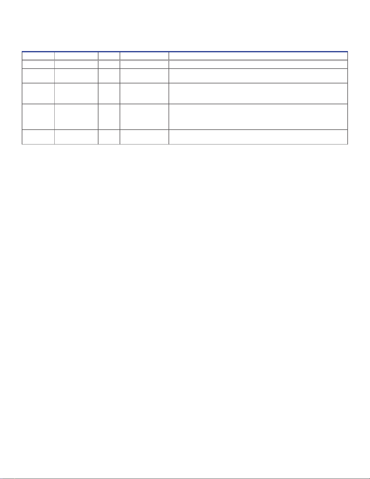
Document History
Revision Date CO Supersession Revision Description
A 27 DEC 2005 3391 n/a Initial release.
B 08 NOV 2007 4324 n/a ♦ Added WEEE symbol to the product specication label and to the manual.
♦Added power supply outlet adapters.
C 04 MAR 2010 5475 n/a ♦ Changed chamber and product specication label style.
♦ Added ISO certication statement.
♦Deleted references to Entela.
D 20 FEB 2013 8268 n/a ♦Added caution label regarding alarm contacts.
♦Updated UL standards compliance label.
♦Changed manual format for improved readability and ease of locating
information within manual.
E 18 MAR 2020 15399 E supersedes D ♦Reformatted document for consistency with other Helmer manuals.
♦Updated compliance information.
* Date submitted for Change Order review. Actual release date may vary.

360112-1/E ii
Helmer Scientic Remote Alarm Monitoring System Operation and Service Manual
Contents
1 About this Manual................................................................................................ 4
1.1 Intended Audience .......................................................................................... 4
1.2 Model References...........................................................................................4
1.3 Intended Use...............................................................................................4
1.4 Safety Symbols and Precautions ...............................................................................4
1.5 Avoiding Injury..............................................................................................4
1.6 Product Labels .............................................................................................5
2 Setup and Installation............................................................................................. 6
2.1 Location Requirements....................................................................................... 6
2.2 Wall Placement .............................................................................................6
2.3 Connect Power Supply ....................................................................................... 6
2.4 Connect Backup Battery ......................................................................................7
3 Conguration.................................................................................................... 8
3.1 Zone Conguration .......................................................................................... 8
3.2 Zone Labels ............................................................................................... 8
3.3 Set Internal Jumpers for Zones.................................................................................9
4 Operation .......................................................................................................11
4.1 Initial Power Up.............................................................................................11
5 Alarms ........................................................................................................ 12
5.1 Visual Alarm Indicators ......................................................................................12
5.2 Audible Alarms ............................................................................................12
6 Maintenance.................................................................................................... 13
6.1 Test Alarms ............................................................................................... 13
6.2 Check the Remote Alarm Monitoring System Battery............................................................... 14
6.3 Clean the Remote Alarm Monitoring System ..................................................................... 14
7 Service ........................................................................................................ 15
7.1 Remove and Install the Cover.................................................................................15
7.2 Circuit Board Replacement................................................................................... 15
8 Troubleshooting ................................................................................................ 16
9 Parts .......................................................................................................... 17
9.1 External Parts ............................................................................................. 17
9.2 Internal Parts..............................................................................................18
10 Schematics .................................................................................................... 19
10.1 RA4..................................................................................................... 19
10.2 RA1..................................................................................................... 19
11 Specications .................................................................................................. 20
11.1 Operating Standards........................................................................................20
11.2 Electrical Specications ..................................................................................... 20
11.3 Input Voltage and Frequency ................................................................................. 20
11.4 Dimensions ...............................................................................................20
12 Regulatory Compliance .......................................................................................... 21
12.1 Safety Compliance .........................................................................................21
12.2 Environmental Compliance................................................................................... 21
Appendix A: Warranty ............................................................................................... 22

360112-1/E 3
Helmer Scientic Remote Alarm Monitoring System Operation and Service Manual
1 About this Manual
1.1 Intended Audience
This manual is intended for use by end users of the remote alarm and authorized service technicians.
1.2 Model References
Generic references are used throughout this manual to group models that contain similar features. For example, “RA models” refers to
all models of that conguration (RA1, RA4). This manual covers all remote alarms, which may be identied singly, by their size, or by
their model designation (RA).
1.3 Intended Use
Helmer remote alarm monitoring systems are intended for the monitoring of alarm systems of refrigerators, freezers, and other medical
and scientic products.
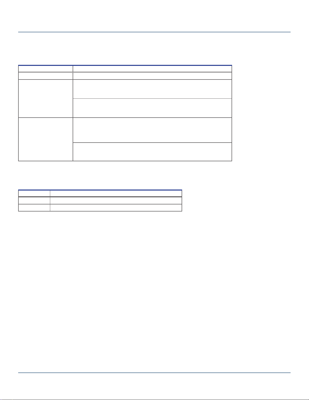
1.4 Safety Symbols and Precautions
Symbols and precautions found in this document
The following symbols are used in this manual to emphasize certain details for the user:
Task Indicates procedures which need to be followed.
Note Provides useful information regarding a procedure or operating technique when using Helmer Scientic
products.
NOTICE Advises the user against initiating an action or creating a situation which could result in
damage to equipment; personal injury is unlikely.
Symbols found on the units
The following symbols may be found on the agitator or agitator packaging:
Caution: Risk of damage to equipment or danger to operator
1.5 Avoiding Injury
Review safety instructions before installing, using, or maintaining the equipment.
♦Avoid removing electrical service panels and access panels unless so instructed.
♦Use manufacturer supplied power cords only.
♦REQUIRED: Decontaminate parts prior to sending for service or repair. Contact Helmer or your distributor for decontamination
instructions and a Return Authorization Number.
360112-1/E 4
Helmer Scientic Remote Alarm Monitoring System Operation and Service Manual
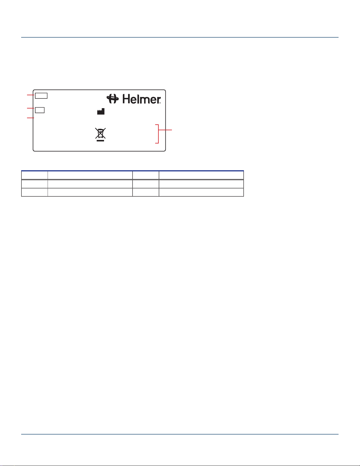
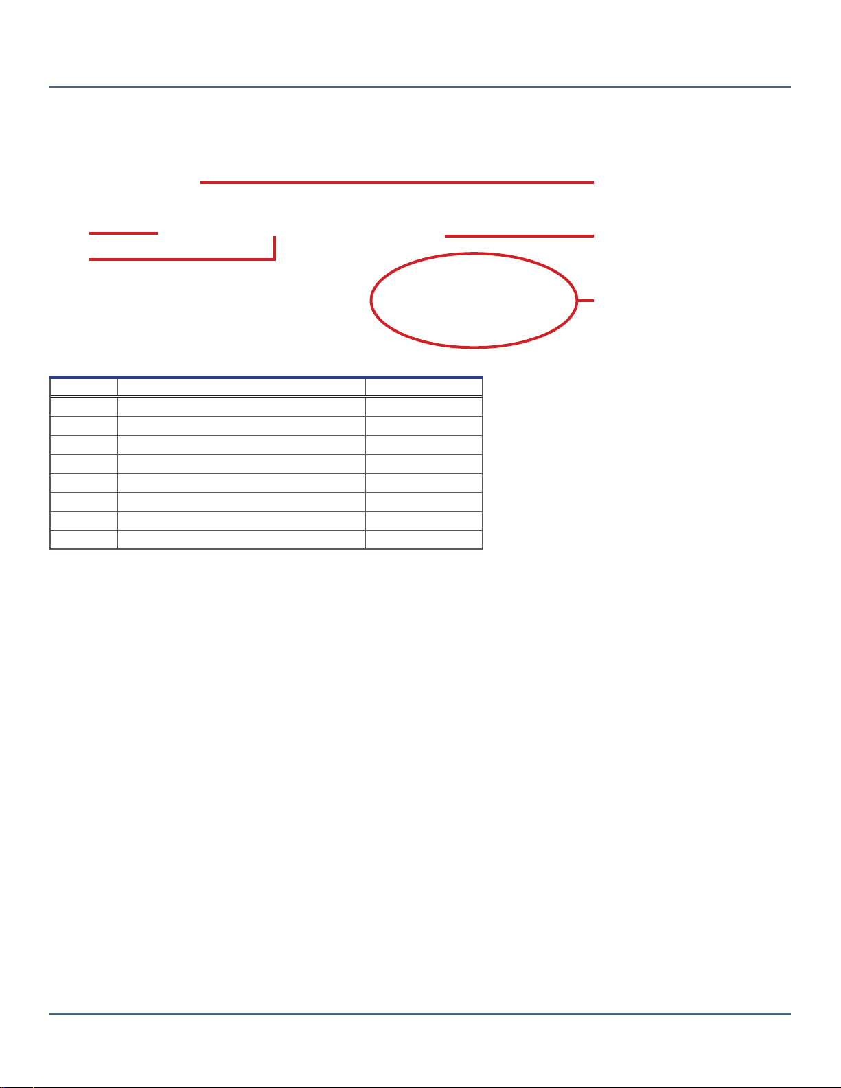
1.6 Product Labels
Note
Service information varies depending on the model.
This information appears on the product specication label, located on the bottom of the monitoring system. The model also appears on
a label located inside the remote alarm monitoring system.
Version A
Remote Alarm
Weight 3 lb / 1.4 kg
14400 Bergen Boulevard
Noblesville, IN USA
www.helmerinc.com
2013
Voltage 12 VDC
Fuse .375 A
Amps .25 A
REF RA4
SN 2000000
D
A
B
C
Sample Product Specication label (located on the back).
Label Description Label Description
AModel (REF) C Version
BSerial number (SN) D Power requirements

360112-1/E 5
Helmer Scientic Remote Alarm Monitoring System Operation and Service Manual
2 Setup and Installation
Notes
• Allow the remote alarm monitoring system to come to room temperature before switching power on.
• During initial startup, the high temperature alarm may sound while monitored equipment reaches operating temperature.
2.1 Location Requirements
♦ Stable, at horizontal surface (desk-mounted) or vertical surface (wall-mounted)
♦Has a grounded outlet meeting national and local electrical requirements
♦ Meets the limits specied for ambient temperature and relative humidity
2.2 Wall Placement
Install Wall Anchors:
1. Use a pencil to mark the wall with the locations for the anchors. The holes are 4-1/8” (105 mm) apart.
2. Install the self-drilling anchors at the marked locations.
3. Using a #2 Phillips screwdriver, install the screws into the anchors, leaving a 1/8” (3 mm) gap between the screw head and
the anchor.
4. Place the monitoring system on the wall so the screw heads protrude into the lower part of the mounting holes.
5. Slide the monitoring system down until the top of the mounting holes rest on the screws.
2.3 Connect Power Supply
The power supply and several adapters are provided for use with a variety of power outlets. The NorthAmerican adapter is installed at
the factory. The power supply and adapters are included with the remote alarm monitoring system.
Monitoring system with power supply and adapters (RA1 model shown with North American adapter installed).
Change the Power Supply Adapter:
1. On the power supply, slide the adapter away from the cord to remove it.
2. Slide the new adapter into place.

360112-1/E 6
Helmer Scientic Remote Alarm Monitoring System Operation and Service Manual
2.4 Connect Backup Battery
A backup battery provides power to the remote alarm monitoring system if AC power fails. The remote alarm monitoring system is
shipped from the factory with the backup battery.
♦The monitoring system has visual and audible alarms to notify when the remaining charge on the installed battery is low.
♦ The low-charge alarms remain active until the battery is removed.
♦If AC power fails, and alarms are not active at the time of failure, the monitoring system can continue to operate on battery
power for a maximum of two hours.
Note
The visual and audible alarms do not indicate whether a battery is installed. The alarms only indicate the battery charge is low.
Battery holder with battery installed (circled).
Note
Use only 9V non-rechargeable alkaline (or equivalent) battery.
Install Backup Battery
1. Disconnect the power to the remote alarm monitoring system.
2. Remove the cover from the base of the remote alarm monitoring system.
3. Install the battery in the battery holder on the circuit board.
4. Replace the cover.
5. Reconnect the power to the remote alarm monitoring system.
Remove Backup Battery:
1. Disconnect the power to the monitoring system.
2. Remove the cover from the base of the remote alarm monitoring system.
3. Remove the battery from the battery holder on the circuit board.
4. Replace the cover.
5. Reconnect the power to the remote alarm monitoring system.

360112-1/E 7
Helmer Scientic Remote Alarm Monitoring System Operation and Service Manual
3 Conguration
Each zone on the remote alarm monitoring system is designed to connect to and monitor one device. Each zone will support
one device.
♦ RA1: One zone (one monitored device)
♦ RA4: Four zones (four monitored devices)
Notes
• Multiple devices to a single zone if all devices are identically congured (all normally-open or normally-closed).
• An active zone alarm indicates that at least one device connected to the zone has an active alarm but does not identify
which device(s) in the zone has triggered the alarm.
3.1 ZoneConguration
Each zone can be independently congured as either a normally-open (NO) or normally-closed (NC) circuit to accommodate the
capability of the device being monitored. At the factory, all zones on the monitoring system are congured as normally-closed circuits.
Normally-ClosedConguration
♦Normal state is a closed circuit between the input and output connectors for the zone.
♦Connecting a device extends the circuit to include that device.
♦When a connected device opens the circuit, an alarm is activated on the remote alarm monitoring system for the
corresponding zone.
♦When the device returns the circuit to the closed state, the alarm is cleared.
Normally-OpenConguration
♦Normal state is an open circuit between the input and output connectors for the zone.
♦Connecting a device extends the circuit to include that device.
♦When a connected device closes the circuit, an alarm is activated on the remote alarm monitoring system for the
corresponding zone.
♦When the device returns the circuit to the open state, the alarm is cleared.
Note
A normally-closed conguration allows for immediate detection if a zone connection is loose or a wire is damaged. These
conditions open the circuit which generates an alarm on the remote alarm monitoring system, even if monitored devices are
not in an active alarm state.
3.2 Zone Labels
On the front of the remote alarm monitoring system, each zone has an area to place a label that identies the monitored device. Blank
labels are provided with the remote alarm monitoring system.
Label area for zone (circled).

360112-1/E 8
Helmer Scientic Remote Alarm Monitoring System Operation and Service Manual
3.3 Set Internal Jumpers for Zones
Each zone has a corresponding internal jumper that is used to congure it as a normally-open or normally-closed circuit. The internal
jumpers are located on the circuit board inside the monitoring system.
Note
Default factory setting is normally-closed.
Internal jumpers. Zones are labeled ZN and the positions for each zone are labeled NC and NO. RA4 model shown with zone 3
jumper in the NO position and the remaining zone jumpers in the NC position.
Set a Zone Jumper:
NOTICE
Before removing the cover, disconnect the power to the monitoring system to eliminate the potential of electric shock.
1. Disconnect the power to the remote alarm monitoring system.
2. Remove the cover from the base of the monitoring system. For instructions, see Section 3.5, “Removing and installing
the cover.”
3. Inside the monitoring system, on the circuit board, locate the jumper for the zone conguration to be changed.
4. Move the jumper to the appropriate position. For a normally-closed conguration, move the jumper to connect the pins that are
labeled NC. For a normally-open conguration, move the jumper to connect the pins that are labeled NO.
5. Replace the cover.
6. Connect the power to the remote alarm monitoring system.
3.4 Connect Monitored Devices
Note
Each zone on the monitoring system is designed to monitor one device.
Multiple Devices Connected to a Single Zone
♦ Multiple devices may be connected to a single zone, provided all devices are identically congured (all normally-open or
normally-closed).
♦With multiple devices connected to a single zone, alarm information received by the remote alarm monitoring system would
be limited.
♦An active alarm indicated that at least one device connected to the zone has an active alarm.
♦ There is no way to identify which device(s) has the active alarm.

360112-1/E 9
Helmer Scientic Remote Alarm Monitoring System Operation and Service Manual
Maximum Distance for Monitored Devices
♦ Monitored devices can be a maximum of 3000’ (915 m) away from the remote alarm monitoring system when connected with
22-gauge wire.
♦When multiple devices are connected to a single zone, the maximum distance refers to the length of wire needed to reach the
device farthest from the remote alarm monitoring system.
Default Connection Settings
♦ The default factory settings for the RA1 zone and RA4 zones is normally-closed.
♦An external jumper connects the two terminals for each zone.
♦ The connections depend on whether the zone will be normally-open or normally-closed, and whether one or more devices is
connected to the zone.
Zone connections for a normally-closed conguration. Left: One device. Right: Multiple devices.
Zone connections for a normally-open conguration. Left: One device. Right: Multiple devices.
Connect Devices to a Zone
1. Conrm the internal jumper for the zone is set appropriately.
2. On the top panel of the remote alarm monitoring system, using a #2 Phillips screwdriver to loosen the screw terminals remove
the external jumper that connects the terminals (if installed) .
3. Connect the zone to the device(s) according to the illustrations above using two-conductor, 22 gauge wire.

360112-1/E 10
Helmer Scientic Remote Alarm Monitoring System Operation and Service Manual
4 Operation
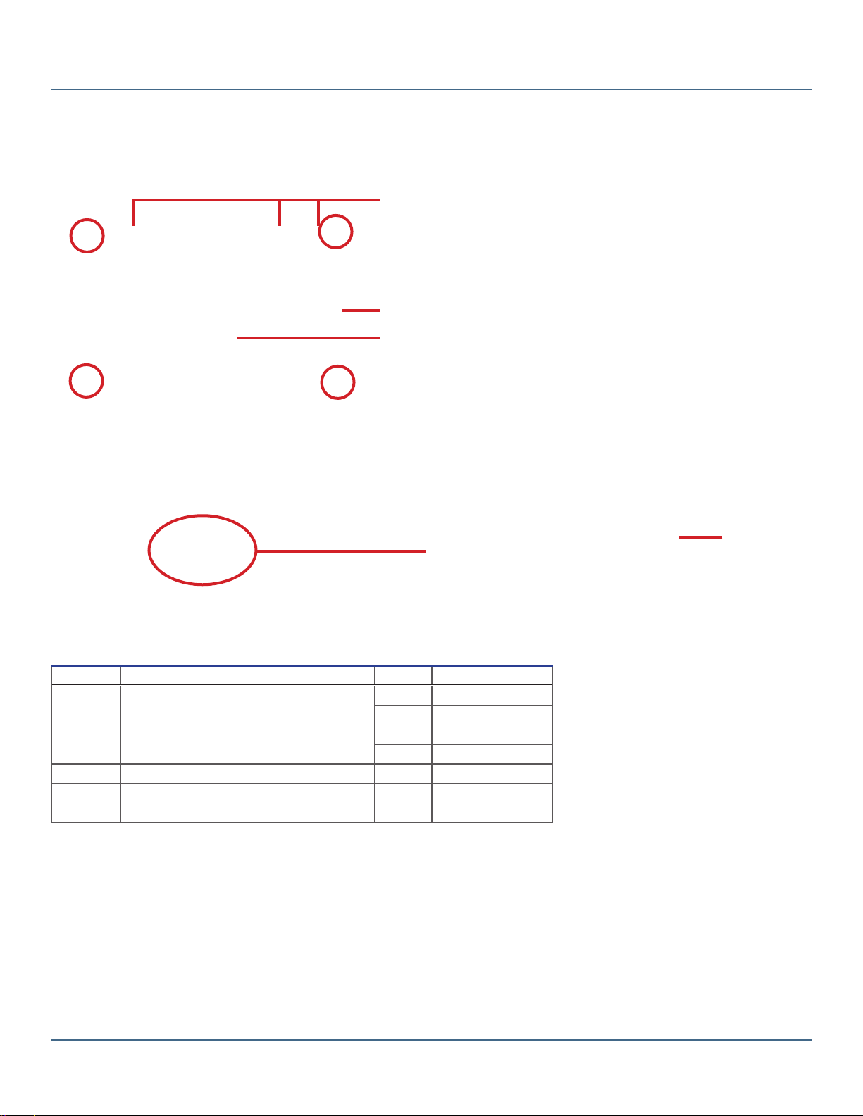
A
B
C
D
E
F
G
H
I J K L
Front features (RA4 model shown). Top features (RA4 model shown).
Label Description Function
A Mute button Mutes audible alarms for 30 minutes
B Alarm buzzer Audibly indicates an active alarm
C Low battery indicator Indicates low battery charge
D Volume control Controls the volume for audible alarms
E Zone number Identies the zone used to monitor a device
F Zone Secure lamp Indicates when a zone is secure (no active alarms)
GZone Alarm lamp Indicates when a zone is in an active alarm state
HZone identication label area Description of the device being monitored
I Power connector Interface for the power cord
J Remote alarm interface Provides a dry contact connection to external central alarm systems
K Zone input and output terminals Connects to the remote alarm interface on devices
L External jumper Completes a normally-closed circuit
4.1 Initial Power Up
The interface on the remote alarm monitoring system is intended for connection to the end user’s central alarm system(s)
that uses normally-open or normally-closed dry contacts.
NOTICE
If an external power supply exceeding 33 V r.m.s. or 70 V (DC) is connected to the remote alarm monitoring system’s circuit,
the remote alarm will not function properly; may be damaged; or may result in injury to the user.
Connect Remote Alarm Monitoring System
1. Connect the power cord to the connector located on the top panel of the remote alarm.
2. Plug the power cord into a grounded outlet meeting electrical requirements stated on the product specication label. The Zone
Secure lamps illuminate.
360112-1/E 11
Helmer Scientic Remote Alarm Monitoring System Operation and Service Manual
5 Alarms
The remote alarm monitoring system provides both visual and audible indicators to signify an alarm state.
5.1 Visual Alarm Indicators
Description Function
Low battery indicator Battery charge is low. Replace the battery.
Zone Secure lamp Lamp ON (ashing) indicates one of the following:
♦ No active alarm(s) for the connected device(s).
♦No devices are connected to the zone.
Lamp OFF indicates one of the following:
♦ Active alarm(s) for the connected device(s).
♦Power is disconnected from the remote alarm monitoring system.
Zone Alarm lamp Lamp ON (ashing) when the zone is in an alarm state, indicating one of the following:
♦ Active alarm(s) for the connected device(s).
♦ Device(s) is connected incorrectly.
♦ Problem with the circuit (normally-closed conguration only).
Lamp OFF indicates one of the following:
♦ No active alarm(s) for the connected device(s).
♦Power is disconnected from the remote alarm monitoring system.
5.2 Audible Alarms
A three-position volume switch adjusts the alarm volume. Pressing the Mute button mutes an audible alarm.
Tone Indication
Constant Zone alarm is active (if the alarm has not been muted).
Intermittent Battery charge is low.
Zone Alarms
♦Volume may be adjusted or muted.
♦Changing volume or muting alarm applies to audible alarms on the remote alarm monitoring system.
♦Volume or mute for the monitored device is controlled through the device itself.
♦Muting an alarm silences the alarm for approximately 30 minutes.
♦If another alarm is activated from a monitored device while an alarm on the remote alarm monitoring system is muted, the
mute timer is reset and the alarm sounds.
Low Battery Alarm
♦Volume can not be adjusted or muted.
360112-1/E 12
Helmer Scientic Remote Alarm Monitoring System Operation and Service Manual
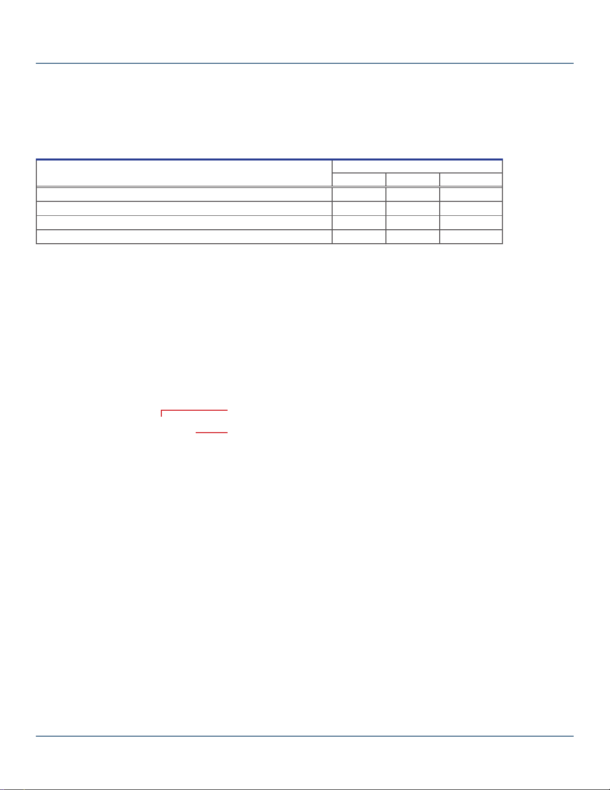
6 Maintenance
Maintenance tasks should be completed according to the following schedule.
Note
These are minimum requirements. Regulations for your organization or physical conditions at your organization may require
maintenance items to be performed more frequently. Follow the guidelines for your organization.
Task
Frequency
Quarterly Annually As Needed
Test the alarms. ü
Check the backup battery. Replace the battery if it has been in service for 1 year. ü
Clean the exterior of the remote alarm monitoring system. ü
Clean the interior of the remote alarm monitoring system. ü
Notes
• During a power failure, the backup battery provides power to the remote alarm monitoring system.
• If the backup battery does not provide power to the remote alarm monitoring system during a power failure or battery test,
replace the battery.
6.1 Test Alarms
Test alarms to ensure they are working correctly. The remote alarm monitoring system provides real-time monitoring of alarm status for
all connected devices.
Zone Secure Lamp
Zone Alarm Lamp
Front features (RA4 model shown).
Note
Refer to the device’s service manual for information on which device alarms are transmitted through the respective device’s
remote alarm interface.
Test the Alarms
1. On a device monitored by the remote alarm monitoring system, manually trigger an alarm that is transmitted through the
remote alarm interface.
2. On the remote alarm monitoring system, verify the zone corresponding to the device with the alarm is in an alarm state.
The red Zone Alarm lamp should be ashing.
3. On the monitored device, clear all active alarms.
4. On the remote alarm monitoring system, verify the tested zone is in a secure state. The green Zone Secure lamp should
be illuminated.

360112-1/E 13
Helmer Scientic Remote Alarm Monitoring System Operation and Service Manual
6.2 Check the Remote Alarm Monitoring System Battery
The monitoring system does not indicate the charge level of the battery. Regularly test the battery. Replace battery if the test fails or if
the battery has been in use for one year.
Test the battery
1. Disconnect the power to the remote alarm monitoring system. The Zone Secure lamp should remain illuminated. If the Zone
Secure lamp is not illuminated, replace battery.
2. Connect the power to the remote alarm monitoring system.
Note
Use only 9V non-rechargeable alkaline (or equivalent) battery.
6.3 Clean the Remote Alarm Monitoring System
NOTICE
Disconnect remote alarm monitoring system from AC power when cleaning.
In environments where remote alarm monitoring system is exposed to excessive lint or dust, cleaning may be required more frequently
than stated in preventive maintenance schedule.
Clean Exterior
Clean exterior surfaces with soft cotton cloth and non-abrasive liquid cleaner. Clean alarm terminals with a soft brush and a
vacuum cleaner.
Clean Interior
Clean the interior using a soft brush and a vacuum cleaner.

360112-1/E 14
Helmer Scientic Remote Alarm Monitoring System Operation and Service Manual
7 Service
7.1 Remove and Install the Cover
NOTICE
Before removing the cover, disconnect the power to the remote alarm monitoring system to eliminate the potential of
electric shock.
Note
After removing the cover, internal wiring will connect the cover to the base.
Screws securing the cover to the base (circled).
Remove the Cover:
1. Disconnect the power to the remote alarm monitoring system.
2. Using a screwdriver, loosen and remove the screws that secure the cover to the base.
Install the Cover:
1. Place the cover over the base, aligning the screw holes.
2. Using a screwdriver, install the screws to secure the cover to the base.
3. Connect the power to the remote alarm monitoring system.
7.2 Circuit Board Replacement
NOTICE
Before removing the cover, disconnect the power to the remote alarm monitoring system to eliminate the potential of
electric shock.
Replace Circuit Board
1. Disconnect the power to the remote alarm monitoring system.
2. Using a screwdriver, loosen and remove the screws that secure the cover to the base.
3. Disconnect the wires from the circuit board.
4. Remove the four nuts that secure the board. Lift the board out of the base.
5. Install the new board and four nuts to secure the board.
6. Connect connect the wires to the circuit board.
7. Place the cover over the base, aligning the screw holes.
8. Using a screwdriver, install the screws to secure the cover to the base.
9. Connect the power to the remote alarm monitoring system.

360112-1/E 15
Helmer Scientic Remote Alarm Monitoring System Operation and Service Manual
8 Troubleshooting
NOTICE
Review all safety instructions prior to troubleshooting.
Problem Possible Cause Action
No Zone Secure or Zone Alarm
lamps are illuminated. No power (AC or battery backup) to
the remote alarm monitoring system. Verify the power cord is connected. Secure the connections if necessary.
Verify the fuse has not blown. Replace the fuse if necessary.
Verify the outlet is operational.
Verify the backup battery is installed and is not depleted. Install or replace
the battery if necessary.
Power supply is faulty. Replace the power supply.
Lamps are faulty. Replace the circuit board.
Circuit board is faulty. Replace the circuit board.
A Zone Alarm lamp is illuminated
but there are no active alarms on
any device connected to the zone.
A connection is loose between the
monitoring system and the device. Check the connections on the device and the monitoring system.
Wrong terminals are connected. Check that connections are correct for the conguration (NO or NC).
Internal jumper for the zone is set
incorrectly. Check that internal jumper settings are correct for the conguration (NO
or NC).
Circuit board is faulty. Replace the circuit board.
A Zone Alarm lamp is illuminated
but there is no audible alarm. Audible alarm is muted. Activate an alarm on a connected device. Verify the alarm sounds on the
remote alarm monitoring system.
Buzzer for the zone alarms is faulty. Replace the alarm buzzer.
Circuit board is faulty. Replace the circuit board.
The Low Battery lamp is
illuminated but there is no audible
alarm.
Buzzer for the low battery alarm is
faulty. Replace the circuit board.
Circuit board is faulty. Replace the circuit board.
The audible alarm sounds, but no
Zone Alarm lamps are illuminated. Battery charge is low. Check that the Low Battery lamp is illuminated. Replace the battery if
necessary.
Zone alarm lamps are faulty. Replace the circuit board.
Buzzer for the zone alarms is faulty. Replace the alarm buzzer.
Buzzer for the low battery alarm is
faulty. Replace the circuit board.
Circuit board is faulty. Replace the circuit board.
360112-1/E 16
Helmer Scientic Remote Alarm Monitoring System Operation and Service Manual
9 Parts
9.1 External Parts
Label Description Part Number
A Zone input and output terminal strip 120506
B Remote alarm interface terminal strip 120404
CZone identication label 715111 (sheet of 36)
D Power supply 120508
E Adapters for power supply 120517
Not Shown Foot 220441
Not Shown Mounting kit 230350
Not Shown External jumper 230351
AD
C
B
E
360112-1/E 17
Helmer Scientic Remote Alarm Monitoring System Operation and Service Manual
9.2 Internal Parts
NOTICE
Before removing the cover, disconnect the power to the remote alarm monitoring system to eliminate the potential of
electric shock.
Circuit board and nuts (circled).
Left: Fuse (circled). Right: Alarm buzzer.
Label Description Model Part Number
A Wire harness kit RA4 400664-2
RA1 400664-1
B Circuit board RA4 400653-1
RA1 400653-2
CBackup battery (9 V alkaline, non-rechargeable) 120218
DFuse (0.375 A) 120501
E Alarm buzzer 120160
A
B
C
DE

360112-1/E 18
Helmer Scientic Remote Alarm Monitoring System Operation and Service Manual
10 Schematics
10.1 RA4
MAIN POWER
100 V ac to 240 V ac
50/60 Hz
F1
(D) CIRCUIT BOARD
12 V dc, 0.25 A
POWER
ADAPTER
POWER
SUPPLY
LN
(G)
BATTERY
1
J3
(F)
ALARM
BUZZER
J4
1
J1
1
J2
ZN4
NC | NO
ZN3
NC | NO
ZN2
NC | NO
ZN1
NC | NO
INTERNAL
JUMPERS
+
-
N
L
1
2
3
4
(A) ZONE INPUT
AND OUTPUT
TERMINAL STRIP
(B) REMOTE
ALARM INTERFACE
TERMINAL STRIP
POWER
CONNECTOR
(C) WIRE
HARNESSES
10.2 RA1
MAIN POWER
100 V ac to 240 V ac
50/60 Hz
F1
(D) CIRCUIT BOARD
12 V dc, 0.25 A
POWER
ADAPTER
POWER
SUPPLY
LN
(G)
BATTERY
1
J3
(F)
ALARM
BUZZER
J4
1
J1
1
J2
ZN1
NC | NO
INTERNAL
JUMPER
+
-
N
L
1
(A) ZONE INPUT
AND OUTPUT
TERMINAL STRIP
(B) REMOTE
ALARM INTERFACE
TERMINAL STRIP
POWER
CONNECTOR
(C) WIRE
HARNESSES

360112-1/E 19
Helmer Scientic Remote Alarm Monitoring System Operation and Service Manual
11 Specications
11.1 Operating Standards
These units are designed to operate under the following conditions:
♦Indoor use only
♦ Ambient temperature range: 5 ºC to 40 ºC (41 ºF to 104 ºF)
♦ Relative humidity (maximum for ambient temperature): 80%
♦ Remote alarm monitoring system can be mounted up to 3000’ (915 m) from monitored device, when connected with 22-gauge wire
♦ Sound level is less than 70 dB(A).
11.2 ElectricalSpecications
Refer to specication label for voltage and power consumption requirements. The remote alarm monitoring system is intended to be
supplied by a LPS (limited power source) power unit, or one designated as “Class 2” and rated at 0.25 A, at 12 V (DC).
Fuse rating is 0.375 A.
11.3 Input Voltage and Frequency
♦ 100 V (AC) to 240 V (AC), 50 Hz to 60 Hz.
♦Input power varies depending on the destination of the remote alarm.
11.4 Dimensions
All dimensions are for the overall exterior and include items that protrude from the main unit.
Model Wall-mounted Desk-mounted
Width
RA1, RA4
8.25 in
210 mm 8.25 in
210 mm
Height 5.75 in
147 mm 2.75 in
70 mm
Depth 2.75 in
70 mm 5.75 in
147 mm
Weight 3 lbs
1.4 kg
This manual suits for next models
1
Table of contents
Popular Measuring Instrument manuals by other brands

Viavi
Viavi SmartClass Fiber OLS-85 user guide

Tektronix
Tektronix 492, 492P Operator's manual

Stark
Stark LL 0501 user manual

PCB Piezotronics
PCB Piezotronics IMI SENSORS 683A000000 Installation and operating manual

Ametek
Ametek 3050-AMS user manual

Fluke Biomedical
Fluke Biomedical RaySafe Xi 8201011 user manual

Huazheng
Huazheng HZ2831 manual

Grundfos
Grundfos iSolutions Monitor instructions

Jaeger
Jaeger 64538-300-1 COMPONENT MAINTENANCE MANUAL WITH ILLUSTRATED PARTS LIST

Power Measurement
Power Measurement ION 8300 user guide

Tyco
Tyco FireClass 801RIL quick start guide

Siemens
Siemens Sitrans F Series operating instructions


