hengel RS10 Quick start guide

INSTRUCTIONS NOTE
page 1 out of 37
Deep - Freezer and Storage Range
Reference SC-NI-EN-2008-4
Updated
Date
Nature of the evolution
1
16/12/08
Details on the assembly of shutter
2
22/04/10
Place of thermosensor probe
3
13/04/11
Adding of COMBITEMP and MULTITEMP
4
11/03/2014
New keyboard with digital display Bi Tronic 2
RS10 to RS110
MAJOR DUO 2 and MAJOR QUATTRO 2
CS10 to CS110
DUO 2 and QUATTRO 2
Basic and aditional module RCM20 to RCM3-20
Basic and aditional module RCN20 to RCN80
Basic and aditional module CCN20 to CCN80
Basic and aditional module RCP20 to RCP80
Basic and aditional module CCP20 to CCP80
Attached document
To preserve by the user
To preserve by the fitter
Electric diagrams+ technician parameters
X
Hengel, Performance at any degrees
ZA Les Berges du Rhins - 42120 PARIGNY - France
Tel: +33 4 77 23 40 00 - Fax: +33 4 77 23 40 09
website :www.hengel.com
Note to be preserved by the user

DEEP-FREEZER AND STORAGE RANGE
page 2 out of 37
The Hengel machines are particularly simple to go up. However, it is imperative of reading this instructions note
attentively.
Before the assembly, check the presence of the power supply cable of the machine. This cable must be with the
top of the machine. (either with a 2200 mm height of the ground)
1Presentation...........................................................................................................................................................................................................3
1.1 General presentation.......................................................................................................................................................................................3
1.2 Technical description .....................................................................................................................................................................................3
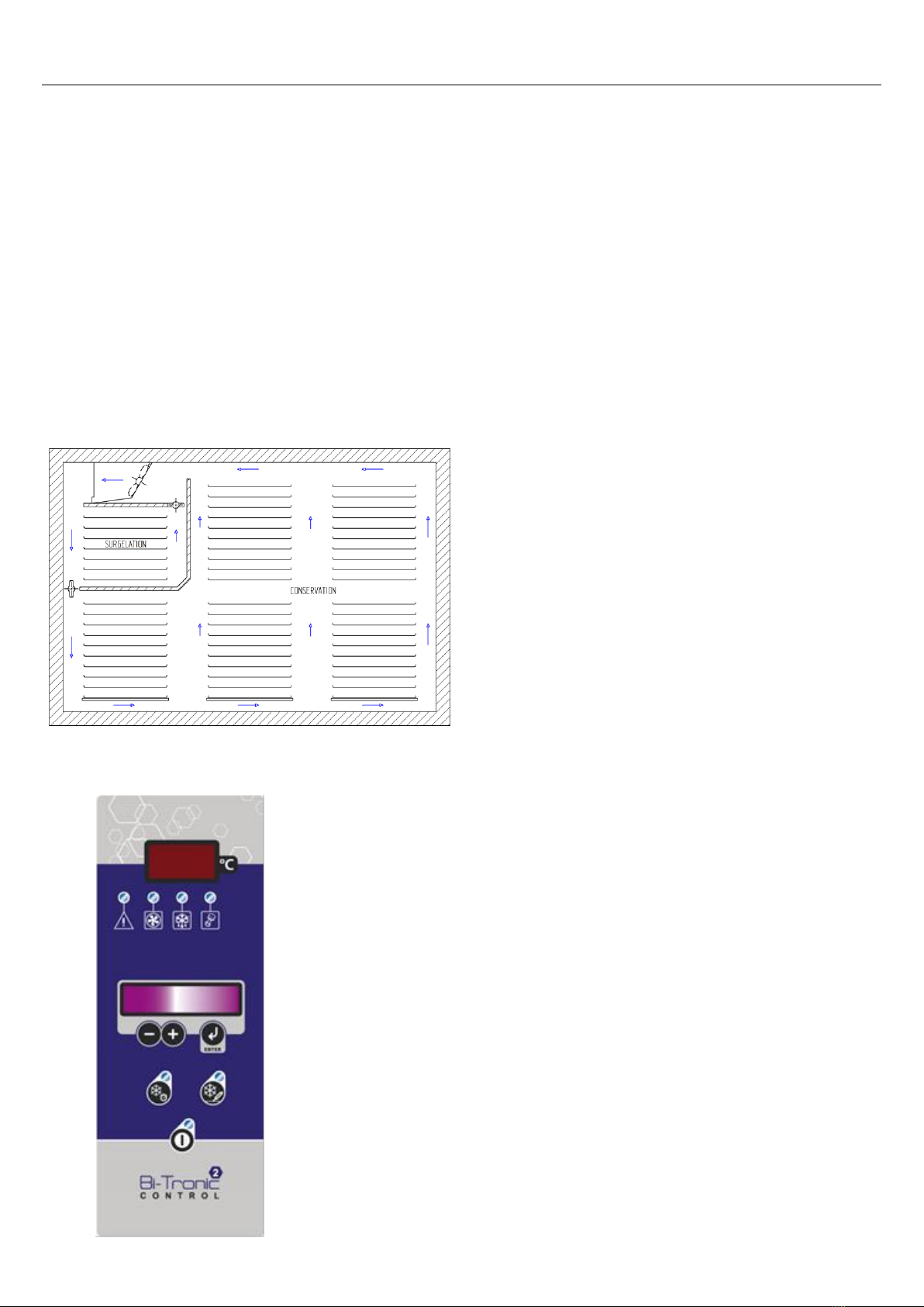
1.2.1 Principle of circulation of air.................................................................................................................................................................3
1.2.2 The Bi-tronic Control regulation (except MULTITEMP) .....................................................................................................................3
1.2.3 The thermo-sensor (range of deep-freezers) ..........................................................................................................................................4
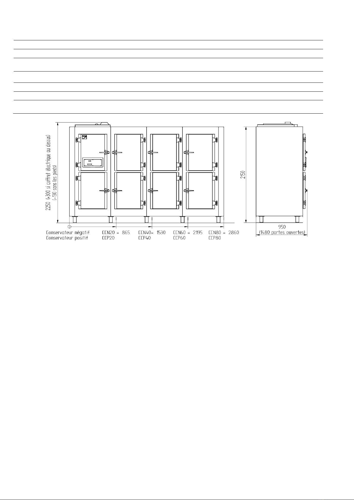
1.3 Technical data for Deep-freezer range............................................................................................................................................................4
1.4 Technical data for storage range.....................................................................................................................................................................6
2Important notes......................................................................................................................................................................................................8
2.1 General instructions of installation and operation ..........................................................................................................................................8
2.2 Instructions of transport..................................................................................................................................................................................8
2.3 Instructions of demolition...............................................................................................................................................................................8
3Instructions of installation.....................................................................................................................................................................................9
3.1 Assembly of the case......................................................................................................................................................................................9
3.1.1 Burst sight of the machine (range of deep-freezers) ..............................................................................................................................9
3.1.2 Burst sight of the machine (range of conservatives)............................................................................................................................10
3.1.3 Burst sight of the machine (range of COMBITEMP AND MULTITEMP conservatives)..................................................................11
3.1.4 Assembly of the grounds.....................................................................................................................................................................13
3.1.5 Assembly of the back panel.................................................................................................................................................................14
3.1.6 Frontage assembly...............................................................................................................................................................................14
3.1.7 Assembly of the first side (left side of the equipment)........................................................................................................................14
3.1.10 Assembly of the second side panel..................................................................................................................................................16
3.1.11 Position of shutters on deep-freezer................................................................................................................................................17
3.1.12 Assembly of evaporator sheets and plate of separation (range of deep freezers, except duo2 and quattro2) ..................................18
3.1.13 Assembly of air guide plates ...........................................................................................................................................................19
3.2 Electric connections .....................................................................................................................................................................................20
3.2.1 Installation of the electric box .............................................................................................................................................................20
3.2.2 Installation of the environment probe..................................................................................................................................................20
3.2.3 Installation of the thermosensor probe (range of deep-freezers)..........................................................................................................20
3.2.4 Connection of the servo-motor (range of deep-freezers) .....................................................................................................................20
3.2.5 Installation of the BUS cable connecting the electric box and keyboard.............................................................................................20
3.2.6 Connection of the door-contact............................................................................................................................................................20
3.2.7 Connection of the door contacts ..........................................................................................................................................................20
3.2.8 Connection of the electric box.............................................................................................................................................................21
3.3 Refrigerating connections.............................................................................................................................................................................21
3.4 Drainage of condensates...............................................................................................................................................................................21
3.5 Finishings.....................................................................................................................................................................................................22
3.5.1 Interior of the equipment .....................................................................................................................................................................22
3.5.2 Adjustement of the doors (wickets).....................................................................................................................................................22
3.6 Step of first startup.......................................................................................................................................................................................22
3.6.1 Instructions for the first use.................................................................................................................................................................22
3.6.2 Introduction of the Bi-tronic Control interface....................................................................................................................................23
3.6.3 Technician Parameters Bi-tronic Control regulation ...........................................................................................................................23
4Use of the Machine..............................................................................................................................................................................................24
4.1 Use of Bi-tronic Control regulation..............................................................................................................................................................24
4.1.1 Starting up (storage mode)...................................................................................................................................................................24
4.1.2 Deep-freezing cycle with time control (range of deep-freezers)..........................................................................................................24
4.1.3 Deep freezing cycle with the Thermo sensor probe (range of deep-freezers)......................................................................................25
4.1.4 Defrosting............................................................................................................................................................................................26
4.1.5 Clock set up.........................................................................................................................................................................................26
4.1.6 Alarms.................................................................................................................................................................................................26
4.1.7 Stop of the interface of regulation .......................................................................................................................................................27
4.2 Utilisation council ........................................................................................................................................................................................28
4.2.1 Information over times of deep freezing, storage and defrosting of the products................................................................................28
5Maintenance of the equipment ............................................................................................................................................................................29
5.1 Cleaning of the machine (Twice a year).......................................................................................................................................................29
5.2 Maintenance of the equipment (2 to 3 times per year)..................................................................................................................................29
5.3 Malfunctions / Maintenance assistance ........................................................................................................................................................30
6Access to the various spare parts.........................................................................................................................................................................32
6.1 Shutter elements (range of deep-freezers) ....................................................................................................................................................32
6.2 Evaporator elements .....................................................................................................................................................................................33
6.3 Frontage elements.........................................................................................................................................................................................34
6.4 Door’s element .............................................................................................................................................................................................35
7Additional information........................................................................................................................................................................................36
7.1 Declaration CE of conformity ......................................................................................................................................................................36
7.2 Contacts of your installer..............................................................................................................................................................................37

DEEP-FREEZER AND STORAGE RANGE
page 3 out of 37
1 Presentation
1.1 General presentation
The company HENGEL thanks you for your trust.
The HENGEL equipment are the result of a long experience in the deep-freezing, storage and retarder proving field for
bakery and pastry products.
Thanks to its expertise, HENGEL is able to meet all the professionals’ specificities and to offer several machines ensuring
a great deep freezing-storage quality, a great proving control, but also an irreproachable material quality, perfectly
adapted to the constraints of the profession.
This note of instructions will enable you to understand, to install and to use the equipment you have just acquired under
the best possible conditions.
1.2 Technical description
The deep freezer Hengel are equipped with a refrigerating unit and an evaporator leaving the possibility of extending the
machine later on to eleven compartments of storage.
1.2.1 Principle of circulation of air
Placed between the compartment of deep freezing and the
storage one, the separation panel opens and closes
shutters for the passage of air and thus manages the
distribution of the cold, thanks to its servo-motor. The logic
of air circulation created by Hengel ensures a
homogeneous temperature in the whole equipment.
Moreover, it allows toavoid the products dryness because of
the air blowing done along the walls of the machine, making
it possible to diffuse naturally in the center of the
compartments.
1.2.2 The Bi-tronic Control regulation (except MULTITEMP)
This regulator offers many reliable functions that were designed to
facilitate your daily tasks.
ERGONOMICS
keyboard of control at the eyes’ level
clear messages
easy cleaning
SIMPLICITY
simple and intuitive use
permanent display :
cycle in progress
instructions in progress internal temperature
FUNCTIONALITY
deep freezing with timer
deep freezing with thermo-sensor probe
standard
linear (control of the descent in temperature)
- various possible defrost launchings
- indication in light of the incidents and audible alarm
- stop of ventilation to the opening of the doors
- anti short-cycle on compressor to increase its lifespan

DEEP-FREEZER AND STORAGE RANGE
page 4 out of 37
1.2.3 The thermo-sensor (range of deep-freezers)
An exclusive system of Hengel makes it possible to determine the exact deep-freezing time
for your products.
An electronic probe pricked in the heart of the product to freeze stops the deep-freezing
process automatically as soon as the ideal temperature is reached. This self-management
guarantees appreciable energy savings and an exact and final knowledge of the precise
deep-freezing time for all the products.
1.3 Technical data for Deep-freezer range
RS 600x800 Modular
RS10
RS30
RS50
RS70
RS90
RS110
Appliance widht (mm)
1100
2000
2900
3800
4700
5600
Standard capacity in plates with
spacing of 75mm (2 plates by
levels)
Deep freezing
14
14
14
14
14
14
Storage
20
60
100
140
180
220
Compressor power (R404)(HP)
3 HP
Scroll
3 HP
Scroll
3 HP
Scroll
3 HP
Scroll
3 HP
Scroll
3 HP
Scroll
600x800 Non-modular
MAJOR DUO 2
MAJOR QUATTRO 2
Appliance widht (mm)
1100
2000
Standard capacity in plates with
spacing of 75mm (2 plates by
levels)
Deep freezing
14
14
Storage
20
60
Compressor power (R404)(HP)
2 HP - Hermetic
2 HP - Hermetic

DEEP-FREEZER AND STORAGE RANGE
page 5 out of 37
RS 400x600 Modular
CS10
CS30
CS50
CS70
CS90
CS110
Appliance widht (mm)
865
1530
2195
2860
3525
4190
Standard capacity in plates with
spacing of 75mm
Deep freezing
7
7
7
7
7
7
Storage
10
30
50
70
90
110
Compressor power (R404)(HP)
2 HP
2 HP
2 HP
2 HP
2 HP
2 HP
400x600 Non-modular
DUO 2
QUATTRO 2
Appliance widht (mm)
865
1530
Standard capacity in plates with
spacing of 75mm
Deep freezing
7
7
Storage
10
30
Compressor power (R404)(HP)
2 HP - Hermetic
2 HP - Hermetic

DEEP-FREEZER AND STORAGE RANGE
page 6 out of 37
1.4 Technical data for storage range
Gamme 600x800 negative
RCN20
RCN40
RCN60
RCN80
Appliance widht (mm)
1100
2000
2900
3800
Standard capacity in plates with spacing of 75mm (2 plates
by levels)
36
72
112
154
Compressor power (R404)(HP)
3/4
2
2
2 1/2
Gamme 600x800 positive
RCP20
RCP40
RCP60
RCP80
Appliance widht (mm)
1100
2000
2900
3800
Standard capacity in plates with spacing of 75mm (2 plates
by levels)
36
72
114
156
Compressor power (R404)(HP)
1/2
5/8
5/8
3/4

DEEP-FREEZER AND STORAGE RANGE
page 7 out of 37
400x600 negative
CCN20
CCN40
CCN60
CCN80
Appliance widht (mm)
865
1530
2195
2860
Standard capacity in plates with spacing of 75mm
20
38
58
77
Compressor power (R404)(HP)
1/2
3/4
1 1/2
2
400x600 positive
CCP20
CCP40
CCP60
CCP80
Appliance widht (mm)
865
1530
2195
2860
Standard capacity in plates with spacing of 75mm
20
40
60
80
Compressor power (R404)(HP)
1/2
1/2
5/8
5/8

DEEP-FREEZER AND STORAGE RANGE
page 8 out of 37
2 Important notes
2.1 General instructions of installation and operation
Although the equipment of HENGEL are particularly simple to assemble and use, it is mandatory to attentively read the
instructions in order to ensure operation’s quality and the longevity of the machine.
The HENGEL machines are designed to function under specific temperature, hygrometry and use conditions that are
advisable to be respected for an optimum performance.
The cabinets are designed to function in a nominal environment of 32°C and 70% of hygrometry. Above that, the
performances of the machine might be affected.
The refrigerating unit is designed to function at a maximum ambient temperature of 43°C. Above this temperature, the
breakage risks of the compressor are very significant.
Moreover, more the ambient temperature is low::
- more electric consumption is low
- more the refrigerating power is significant
- more the lifespan of the compressor is long
- better are the performances
Anyway, it is appropriate that the refrigerating unit is installed in a very ventilated place, far from heat sources and
protected from of the sun and the rain.
In case of remote refrigerating units, the length of refrigerating pipings should not exceed 15m. For greater lengths,
please contact HENGEL.
Optimal limits of operation: - Deep freezing: -35°C
- Storage: -20°C/-25°C
Regulate your temperature of storage to –25°C does not improve the storage but generates a higher consumption.
To ensure a correct operation of the machine, do not store in any case your products directly on the ground because it
prevents the air circulation and thus the temperature homogeneity inside the cabinet.
The machine will have to be installed on a flat ground and of level.
The electric feeding and connections will have to be in conformity with the local standards.
It is necessary to envisage the spaces for the door opening and the maintenance
In the context of new standards concerning the cold storage, the leak detection must be performed
annually by qualified professionals.
2.2 Instructions of transport
All the machine’s elements are protected by packings.
These packings should not be exposed to bad weather. Avoid exposing them to significant temperature changes.
The loading and unloading of the transport vehicle can be made through a forklift.
The payload of the truck must suit the weight of the packaging.
During transport and handling, take all the essential precautions to not damage the various elements of the equipment
contained in the packing.
2.3 Instructions of demolition
For the machines’ demolition, it is essential to addressed to a company specialized in waste disposal.
They will perform the disassembly of the equipment separating its elements and will be in charge of recycling or storing
the discharge.
Any instructions not respected could cause a malfunction of the machine.
The installation, cleaning and maintenance operations must imperatively be carried out by qualified
professionals following the instructions provided in this note.

DEEP-FREEZER AND STORAGE RANGE
page 9 out of 37
3 Instructions of installation
Our machines are simple and fast to assembly. It is however necessary to follow the instructions of assembly attentively.
In case of negligence, difficulties may arise for the ceiling and shutter assembly, which would require the disassembly of
the machine.
3.1 Assembly of the case
3.1.1 Burst sight of the machine (range of deep-freezers)
The machines in its generic form is presented in the following way:
Caution: For the QUATTRO 2 range, the evaporator platform is placed with the electric frame in front of
the machine.
Designation
Ground M-F
Fund M-F
Ceiling M-F
Frontage M-F
Ref
.
50
51
52
53
Designation
Ground M-F
Fund M-F
Ceiling M-F
Frontage M-F
Ref
.
30
31
32
33
Designation
Cheek
ground Male-Male
Fund M-M
Platform
évaporateur
Frontage M-Female
Ref.
00
10
11
12
13
Designation
Slide
Separation
Foot
Channel on ground
Deflector
Prick probe
R
e
f.
G
H
I
J
K
L
Designation
Electric box
Plate under evaporator
Hide evaporator
Shutter
Separation
Environment probe
Ref
.
A
B
C
D
E
F

DEEP-FREEZER AND STORAGE RANGE
page 10 out of 37
3.1.2 Burst sight of the machine (range of conservatives)
The machine in its generic form is presented in the following way :
Designation
Ground M-F
Fund M-F
Ceiling M-F
Frontage M-F
Ref
.
50
51
52
53
Designation
Ground M-F
Fund M-F
Ceiling M-F
Frontage M-F
Ref.
30
31
32
33
Designation
Cheek
ground Male-Male
Fund M-M
Platform
évaporateur
Frontage M-Female
Ref.
00
10
11
12
13
Désignatio
Electric box
Slide
Foot
Réf.
A
G
I

DEEP-FREEZER AND STORAGE RANGE
page 11 out of 37
3.1.3 Burst sight of the machine (range of COMBITEMP AND MULTITEMP conservatives)
Designation
Ground M-F
Fund M-F
Ceiling M-F
Frontage M-F
Divider panel
Ref
.
50
51
52
53
101
Designation
Ground M-F
Fund M-F
Ceiling M-F
Frontage M-F
Ref.
30
31
32
33
Designation
Cheek
ground Male-Male
Fund M-M
Platform
évaporateur
Frontage M-Female
Ref.
00
10
11
12
13
Désignatio
Electric box
Slide
Foot
Réf.
A
G
I

DEEP-FREEZER AND STORAGE RANGE
page 12 out of 37
- Positioning of the machine
Using dimensions of the table of the Technical Data and following diagram, mark the contour of the machine on
the ground. Leave a space of 5cm around the machine to avoid corrosion. Never press it against the wall.
Envisage the place for the tube passage and the drain of condensate siphon.
- Verifying the panels
The machines are labeled with a number in a sticker placed with evidence on the panels. It is advisable to check
the presence of all the panels on the pallets thanks to the burst sight view of the equipment.
TYPE
CHEEK
GROUND
FUNDS
CEILING
FRONTAGE
RS10 –MAJOR DUO
2
CS10 –DUO 2
RCN20 –RCP20
CCN20 –CCP20
00-00
10
11
12
13
RS30–MAJOR
QUATTRO2
CS30 –QUATTRO 2
00-00
10-30
11-31
12-32
13-33
RS50
CS50
RCN60 –RCP60
CCN60 –CCP60
00-00
10-30-50
11-31-51
12-32-52
13-33-53
RS70
CS70
RCN80 –RCP80
CCN80 –CCP80
00-00
10-30-50-70
11-31-51-71
12-32-52-72
13-33-53-73
RS90
CS90
00-00
10-30-50-70-90
11-31-51-71-91
12-32-52-72-92
13-33-53-73-93
RS110
CS110
00-00
10-30-50-70-90-110
11-31-51-71-91-111
12-32-52-72-92-112
13-33-53-73-93-113
During the assembly of the panels, make sure that they are not shifted between each other, and
check the anchoring hook in the female part.
Before the panels’ installation, remove film of protection found on the metal sheet of the panels
(except the ground panel). The assembly of the panels is done by the inside..
1.1 Panneau de sol
posé à l’envers
Refrigerating
connection
and Power
suply

DEEP-FREEZER AND STORAGE RANGE
page 13 out of 37
3.1.4 Assembly of the grounds
Screw the feet on the envisaged location.
The ground must be controlled with a spirit level, which will allow a possible adjustment of the feet.
One foot must necessarily be in each joint between two bottom panels
Once all the ground is assembled, check again the level and the good support of all the panels on the feet.
Protect the soil using a cardboard to prevent scratches
Remove film all around the bottom.

DEEP-FREEZER AND STORAGE RANGE
page 14 out of 37
3.1.5 Assembly of the back panel
Remove film of protection of the back panel
Attach the back panels (11) to the bottom (10) to get started
Attach, lock and verify the good alignment of the panels with the
ground (Fig.A)
Fig.A : Vérifier l’alignement
3.1.6 Frontage assembly
Remove the protection film from the frontage panels.
Implementthe frontage panel (13) ensuring that it is positioned in the
basement on the ground
Attach, lock and verify the alignment of the frontage with the ground
3.1.7 Assembly of the first side (left side of the equipment)
Please follow these steps carefully to get a good
alignment during assembly of the panel:
Remove the protective film from the panel
Place a bead of silicone moldings on the frontage, the ground and
the bottom
Lock the hooks (13-1) and (13-2) of the frontage, verifying the
alignment of the panel and the front part
Lock the hooks (11-1) and (11-2) of the back, verifying the alignment
of the panel and the front part
Lock both hooks of the ground with the side panel
The two hooks left (13-3) and (11-3) must be locked after the
assembly of the platform.
Fig B : Face d’alignement
11
10

DEEP-FREEZER AND STORAGE RANGE
page 15 out of 37
3.1.8 Assembly of the platform
Pose the platform on the bottom and make it slip to connect it on the
side panel.
Lock the plaform hooks from above
Finally lock the hooks on the high panels / frontage and back
Drill a hole enabling the PVC tube passage connected to the
evaporator tank.
Sizing for the case of avacuation in the center of the panel
Drilling for possible evacuation through the floor according to
your needs. In this case, please follow the same sizings
Clean the inside of the equipment after drilling
Vue 3D et photo correspondante au montage de la
plateforme
3.1.9 Assembly of the back and intermediate frontages as well as the separation panels
The following steps do not apply to the models RS10, CS10, Major Duo 2 and Duo 2
Remove the protection film from the second panel of separation
Engage this panel of separation in the U of the back
Position the frontage with hinges at right making sure that the panel is in position in its U
Verify the good alignement of the panels
Lock the frontage hooks.
Position and attach the other back panels (does not apply to the models RS10, CS10, Major Duo 2 and Duo 2)
Lock the back and the bottom once once all the panels are perfectly aligned (3 hooks on the top, 2 hooks on the
bottom)

DEEP-FREEZER AND STORAGE RANGE
page 16 out of 37
3.1.10 Assembly of the second side panel
Remove the protection film of the panel
Pose a silicone cord on the molding of the panel
Position the side panel while taking care of the good alignment of the
panels.
Lock the hooks starting with the ground.

DEEP-FREEZER AND STORAGE RANGE
page 17 out of 37
3.1.11 Position of shutters on deep-freezer
Connection of the servo-motor
Both servo-motors ensure the operation of the
deep freezing –storage of the equipment. The
opening and closing of each servo-motor
determines the operation’s mode.
In order to an optimal operation, we ahve modified
the position of the servo-motor positioned beside
the evaporator (see picture 2).
Picture 2

DEEP-FREEZER AND STORAGE RANGE
page 18 out of 37
3.1.12 Assembly of evaporator sheets and plate of separation (range of deep freezers, except duo2
and quattro2)
The sub-evaporator sheet is shorter than the two plates of separation of the deep-freezing compartment. For an easy
assembly please follow the three next steps by referring to the diagram below.
Place the plate on the evaporator in an inclined manner in order to insert it. Move it to the right to be able to bring it to
the horizontal.
Brin git to the left side. Afterwards align it against the valve of the right servomotor to be able to block it.
Block it using the bracket provided for this purpose
Position the steel plate between the isolating plate and the evaporator; and put it in abutment against the tube of
flow on the left.
Install the air shutter by pulling the key valve to compress the spring, and then switch on the servo-motor.
Afterwards, drag the plate’ separations in the slides ways and fix the air deflector.
In abutment against the flow

DEEP-FREEZER AND STORAGE RANGE
page 19 out of 37
3.1.13 Assembly of air guide plates
The last step in the assembly of the apparatus is the assembly of the air guide plates. You have a number of metal sheets
equivalent to the number of modules of the equipment. They have identical dimensions. For each module, a specific
location has been provided as shown in the following diagram.
This new placement has no impact on the modularity of our deep freezers and storage cabinets. Position the metal
sheet’s holes of the channel in front of those projected on the frontage and back panels of each module.
Warning: sheets of air-guiding channel are not centered compared to the racks, please follow the steps about their
assembly shown in the next diagram.
CAUTION : It is forbidden to put anything on and between the metal sheets of the floor channel, and
the bottom panel of the unit. This would prevent the air circulation and create a large temperature
difference between the different modules of the device
Assembly and fixation of the rounded deflector
Position the deflector in a way that the holes coincide with the floor panel’s hook holes.
Fix the deflector using two gray stoppers delivered with all the stoppers of the equipment.
Finish by placing a bead of silicone between the upper end of the deflector and the side to ensure the sealing.
Round
deflector
Round
deflector

DEEP-FREEZER AND STORAGE RANGE
page 20 out of 37
3.2 Electric connections
3.2.1 Installation of the electric box
Fix the electric box either on the ceiling, or on the top of the side panel, or on a
wall. (The length of the cable is limited to 1m50)
3.2.2 Installation of the environment probe
Pass the probe through the hole of the platform located close to the
separation.
Pass the probe in the vertical tube as shown in the picture.
Fix the probe using the fastener collar.
The environment probe must be placed with the exit of wire downwards
3.2.3 Installation of the thermosensor probe (range of deep-freezers)
Pass the thermosensor probe by this same hole
Also pass the probe in the vertical tube
Fix the probe in the tilted tube (Quattro) or fix the probe on the sheet close to the evaporator
Quattro
Other deep-freezer
3.2.4 Connection of the servo-motor (range of deep-freezers)
Make the cable goes over the servo-motor using the adhesive base plates
and collars.
Pass the cable in the hole located on the top of separation.
Pass the servo-motor’s cable in the hole of the environment probe and the
thermosensor.
Stop this hole with silicone to avoid any passage of air (formation of
frost, then of ice).
3.2.5 Installation of the BUS cable connecting the electric box and keyboard
Pass the BUS cable in the spring located in top of the first door and connected it to the electronic chart in the electric
box.
Stop up this hole with silicone.
3.2.6 Connection of the door-contact
Put in series all the door-contact interrupters (wire blue and chestnut) outgoing the top of the frontages.
Bring back a cable to the electric box and connect it at the boundaries P according to the electric diagram on the
platform.
3.2.7 Connection of the door contacts
Put in derivation resistances of entourage of the doors (purple wire) outgoing top of the frontages according to the
plan inserted with the transformer on the platform.
Connect wire 18V and 24V coming from the transformer following the plan on the platform
Bring back cable 230V to the electric box and connect it to the electronic chart.(see diagram in box)
This manual suits for next models
31
Table of contents