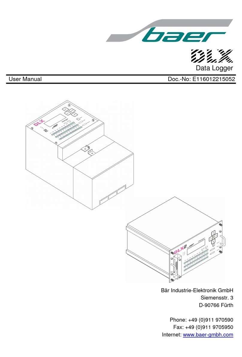
HENGKO HT R71 User manual

- 1 -
PREFACE
Thank you very much for using our ultra-thin widescreen paperless
recorder!
This manual provides methods on performance indicators, installation
and wiring, operation, parameter setting, troubleshooting, etc. Before
using the ultra-thin widescreen paperless recorder, please read this
manual carefully to correctly grasp the use of the method before the
specific operation to avoid unnecessary losses caused by wrong
operation.
After you read it, please keep it properly in the place where you can
read it at any time, so that you can refer to it when you operate it.
DISCLAIMMER
The contents of this manual are subject to change without prior notice
due to function and performance upgrades, etc.
Reproduction or duplication of the contents of this manual, in whole
or in part, is strictly prohibited.
If you find any inaccuracies or errors in this manual, please contact us.

- 2 -
Boxed items
Please check the following items before you use them after opening the
box. Once you receive the product, the quantity is wrong or there is
physical damage in appearance, please contact our company or sales
outlet.
Ultra-thin widescreen paperless recorder Mounting bracket (4pcs))
User manual Product Certificate of Conformity / Warranty Card
Data management software CD

- 3 -
Serial number
Name
Unit
Quantity
Remarks
1
Ultra-thin widescreen
Table
1
paperless recorder
2
Mounting bracket (with
Root
4
For tray
screws)
mounting
fixing
3
Instruction manual
copy
1
4
Product certificate of
copy
1
conformity/warranty
card
5
Data management
sheet
1
software (CD-ROM)
6
USB flash drive
pcs
Optional
Accessorie
s
7
RS-232C
Root
Optional
communication cable
Accessorie
s
8
RS-232C/485
pcs
Optional
conversion module
Accessorie
s
9
Micro printer (with
table
Optional
power supply)
Accessorie
s

- 4 -
Caution
Please contact the manufacturer if you find any damage caused by the
transportation of the instrument when unpacking.
This series of meters is suitable for general industrial applications, if
there are special requirements for use, please set up separate
protection devices.
For the safety of you and the instrument, please do not install with
electricity. Please use the rated voltage power supply, proper wiring,
proper grounding, and do not touch the terminals on the back of the
instrument after the power is turned on to prevent electric shock.
Install the instrument indoors, in a location with good ventilation (to
prevent high internal temperatures), away from rain and direct
sunlight, and never in
1.Where the temperature and humidity exceed the operating
conditions
2.Where corrosive, flammable or explosive gases are present
3.Where there is a large amount of dust, salt and metal powder
4.Where water, oil and chemical liquids are easily spilled
5.Occasions with direct vibration or shock
6.Occasions where electromagnetic sources are generated

- 5 -
The instrument should take corresponding shielding measures when it
is close to the power line, strong electric field, strong magnetic field,
static electricity, noise or AC contactor and other interference.
In order to avoid measurement errors, when the sensor is a
thermocouple, please use the corresponding compensation wire
When the sensor is a RTD, use three copper wires with the same
specifications and resistance value less than 10Ω, otherwise it will
cause measurement errors
To prolong the service life of the instrument, please perform regular
maintenance and servicing. Do not repair or disassemble the
instrument by yourself. When wiping the instrument, please use a
clean soft cloth, do not dip it in alcohol, gasoline and other organic
solvents to clean it, which may cause discoloration or deformation.
If the instrument has water, smoke, odor, noise, etc., please
immediately cut off the power supply, stop using and contact with the
supplier or our company in time.

- 6 -
Table of Contents
Chapter 1 Overview.................................................................................. 8
Chapter 2 Technical Specifications........................................................... 9
Chapter 3 Installation Wiring..................................................................12
3.1
Instrument
dimensions
..................................................................
12
3.2
Opening dimensions.....................................................................13
3.3
Instrument mounting...................................................................
13
3.4
Instrument wiring.........................................................................14
3.4.1
Wiring methods.....................................................................
14
3.4.2
Terminal description..............................................................
16
3.4.3
Terminal schematic wiring diagram...................................... 17
3.4.4
AC/DC power input wiring.....................................................
17
3.4.5
Input signal
wiring
................................................................. 18
3.4.6
Relay contact output wiring.................................................. 18
3.4.7
Transmitter Wiring.................................................................
19
3.4.8
Communication wiring.......................................................... 19
Chapter 4 Basic operation and operation screen...............................
21
4.1
Instrument keys...........................................................................21
4.2
Usage
modes
................................................................................22
4.3
Status flags...................................................................................
23
4.4
General view screen....................................................................
24
4.5
Bar graph screen......................................................................... 27
4.6
Real-time curves..........................................................................
30
4.7
Historical curves..........................................................................32
4.8
PID screen....................................................................................
34
4.9
Power down
list
...........................................................................
35
4.10
Power down list........................................................................ 36
Chapter 5 Configuration and Auxiliary Operations............................38
5.1
Configuration Login.....................................................................38
5.2
Configuration screen...................................................................39
5.3
System configuration...................................................................40
5.4
Input configuration......................................................................
43
5.5
Output configuration...................................................................
49
5.6
Communication configuration.................................................... 50
5.7
Print
configuration
........................................................................
52
5.8
Backup configuration...................................................................
53
5.9
Displaying the
configuration
........................................................ 54
5.10
Control configuration................................................................ 56

- 7 -
5.11
Report query............................................................................. 58
5.12
Function information................................................................ 60
5.13
Explanatory hints and auxiliary interfaces............................. 61
Chapter 6 Fault Analysis and Troubleshooting...................................... 62
Chapter 7 Service Guide......................................................................... 64
Appendix I Bit Number Configuration.................................................. 65
Appendix II Flow rate calculation formula and meter coefficients.....70
Appendix III Compensation Types and Commonly Used Gas Standard
Density....................................................................................................71
Appendix IV Flow rate usage examples................................................. 73
Appendix V PID control loop application examples.............................. 75
Appendix VI Additional/Customized Function Descriptions................. 76

- 8 -
Overview
Chapter 1 Overview
In recent years, some industrial sites are constrained by the
installation depth, the number of data collection channels and operating
comfort, the general traditional products have completely failed to meet
the needs of the site, and brought considerable inconvenience to the use of
the unit on-site application, so a short thickness, high integration, colorful,
comfortable operation, full functionality, high reliability and ideal cost
performance products have great practical significance. The ultra-thin
paperless recorder developed by our company aims to meet the rational
needs of the instrument unit and enhance the perceptual experience of the
instrument unit, mainly used in petroleum and petrochemical, chemical,
paper and plastic, textile printing and dyeing, metallurgy and building
materials, science and education, national defense, biological medicine,
municipal environmental protection, energy measurement, food and oil,
tobacco and wine, equipment manufacturing, equipment sets and
agriculture, forestry, animal husbandry and fishery industries.
Function
Can support touch function (additional function).
Can support dual communication function (additional function)
Timing printing function can be supported (additional function)
Can support DC power supply (additional function)
Can support Ethernet communication function (customized function)
Vacuum degree calculation function can be supported (customized
function)
Communication acquisition function can be supported (customized
function)
Feeder output function can be supported (optional function)
Variable output function can be supported (optional function)
Can support alarm output function (optional function)
Can support PID control function (optional function)
Can support standard serial communication and printing function
(optional function)
Support flow accumulation temperature and pressure compensation
function (optional function)
Data recording / dumping backup function (standard function)
Universal analog input (standard function)

- 9 -
Display
Chapter 2 Technical indicators
Screen: 7-inch true color TFT LCD (800 * 480 dot matrix)
Accuracy: Real-time display: ±0.2% F.S.
Trace accuracy: ±0.2% F.S.
(Note: thermocouple should be removed from the cold end error)
Processor
Using high-performance ARM Cortex-M3 32-bit RISC core, can
simultaneously achieve multiple signal acquisition, recording, display and
multiple alarms
Storage module
The use of large-capacity parallel NAND FLASH flash memory chip to
store historical data, the use of serial FRAM memory chip to store system
configuration parameters and other key information
Input function
Input specifications: fully isolated universal input, maximum support
for 16 analog inputs
Voltage input: 0-5V, 1-5V, 0-20mV, 0-100mV
Current input: 0-10mA, 4-20mA, 0-20mA
Resistance input: Res (0~400Ω)
RTD: PT100, Cu50, G53, Cu100, BA1, BA2 (requires three-wire
resistance balance, lead resistance <10Ω)
Thermocouple: S, B, K, T, R, E, N, J
Radiation pyrometer: F1, F2
Tungsten rhenium: WRe3-25, WRe5-26
Note
Other input signals (such as switch input (DI), pulse input (PI)) or
indexing numbers (such as PT1000) need to be specified when
ordering

- 10 -
Output function
Distribution output: support up to 3 groups of transmitter isolated
distribution +24VDC, each group of distribution ≤ 60mA, support other
specifications isolated distribution (such as 12VDC, 5VDC distribution
output)
Transmission output: support up to 4 channels of standard current
transmission output, with a load capacity of 750Ω (maximum), to facilitate
the acquisition of display instruments or DCS/PLC, to achieve long-distance
transmission of signals
Relay alarm output: up to 6 channels support relay alarm output,
contact capacity 1A@250VAC/1A@30VDC (maximum contact capacity can
be customized), can be configured on the upper limit, upper limit, lower
limit, lower limit alarm
Communication printing
Communication interface: RS232C and RS485 two kinds of
communication interface for users to choose, support simultaneous use of
RS232C and RS485, support simultaneous use of RS232C and RS232C,
support Modbus RTU protocol, baud rate---- (1200, 4800, 9600, 19200,
38400, 57600)
Print interface: RS232C directly connected to a micro printer, baud rate
1200
Recording function
Recording capacity: 64/128/192/248MB (FLASH capacity is optional).
Recording interval: 1 second to 240 seconds, in 11 steps.
1/2/4/8/12/24/36/60/120/180/240 seconds selectable.
Recording time: the length of the recording time is related to the FLASH
memory capacity, the number of input points, and the recording interval,
and the calculation formula is as follows (the units substituted into the
value should be consistent with the formula)
Recorded Days
FlASH Capacity (MB)
1024
1024
Recording Interval (second)
Day
Number of channels16243600

- 11 -
Data dumping
Data backup and dumping: support USB 1.1, 2.0 USB flash drive,
support 1G to 32G USB flash drive for data dumping, strong compatibility,
compatible with most of the U disk on the market (recommended to use
the industrial version of the flash drive)
Power supply
Power supply: 100 ~ 240VAC (rated power supply voltage 220VAC),
50/60HZ AC power supply, support 24VDC (18VDC-36VDC) DC power supply,
support 12VDC (9VDC-18VDC) DC power supply (DC power supply should
be specified when ordering)
Protection function
historical data, permanently stored after power failure
Clock protection: integrated hardware clock, accurate operation even after
power failure
Error accuracy
Thermocouple cold end compensation error: ±2℃
Clock error: ±2 seconds/day
Working environment [prohibited in flammable, corrosive
environment
Operating temperature: 0~50℃(avoid direct sunlight)
Relative humidity: 0~85%R.H (no condensation)
Altitude: <2000m (except for special specifications)
Transportation and storage environment
Transportation and storage temperature:
-20
~
60
℃
(avoid direct
sunlight)
Transportation and storage humidity: 5~95%R.H (no condensation)
Net weight of the instrument
Net weight: ≤1.5Kg

- 12 -
第三章 安装接线
3.1 仪表尺寸
3.2 开孔尺寸
Note
Technical indicators for this series of instruments common indicators,
functional configuration please prevail in kind.
If the technical indicators are inconsistent with the physical instrument,
please take the physical object as the standard.
Chapter 3 Installation Wiring
3.1 Instrument size
Note
When the set meter is installed, the minimum spacing between meters
recommended in the above diagram should be referred to in order to
ensure the necessary space for heat dissipation and loading and unloading.

- 13 -
当集装表安装时,应参考上图中推荐的仪表间最小间距,以保证必要
的散热及装卸空间。
3.3 仪表安装
3.2 Opening size
Note
When the set meter is installed, the minimum spacing between meters
recommended in the above diagram should be referred to in order to
ensure the necessary space for heat dissipation and loading and unloading.
3.3 Instrument Installation
注
意

- 14 -
Installation method.
Step 1: Push the meter into the mounting hole from the front of the
mounting panel (please use a steel plate). Where the thickness of the
mounting panel is (1.5~4.0) mm.
Step 2: Use the mounting bracket that comes with the meter to install it
as shown above (two brackets are installed on the left and right sides of the
meter, and the screws used for the mounting bracket of the instrument
panel are M3 standard screws).
Step 3: After the meter body is installed, the signal and power cables can
be connected。
Note
When installing this instrument, please do not tilt it from side to side, and
try to install it horizontally (it can be tilted back <30°).
3.4 Instrument Wiring
3.4.1
Wiring method
It is recommended to use U-type crimp terminals with insulating sleeve
(M3 screws for power and signal terminals).
To enhance the safety of the instrument, observe the following warnings
when wiring.
Note
To prevent electric shock, make sure the supply power is disconnected
before wiring.
To prevent fire, use double-insulated wire (wire with a cross-sectional area
≥ 0.75 mm² is recommended for the power supply wire; wire with a
cross-sectional area ≥ 0.5 mm² is required for the relay output wire with
high voltage resistance).

- 15 -
Please set an air switch in the power circuit to isolate the meter from the
main power supply.
Tighten the terminal screws firmly. Tightening torque: 0.5 N.m (5 kgf.cm).
After connecting the power cord, you should connect the power supply to
check whether the meter is normal. Do not connect the signal line before
that, and after confirming that the meter can work normally, disconnect the
power supply and then connect the signal line.
The measurement circuit and the power circuit should be laid separately,
and the measurement object should preferably not be a source of
interference. If this cannot be avoided, please insulate the measurement
object and the measurement circuit and ground the measurement object.
For the interference generated by static electricity, it is better to use
shielded wire.
For interference caused by electromagnetic induction, it is better to
connect the measurement circuit wiring in dense strands at equal
distances.
If the input wiring is connected in parallel with other instruments, the
measured values will be affected by each other. When parallel connection is
necessary, be careful not to switch the power supply of one of the
instruments during operation, as this may have an adverse effect on the
other instruments. RTDs cannot be connected in parallel in principle, and
current signals cannot be connected in parallel in principle.

- 16 -
When thermocouple input, please do not use thick wire with good heat
dissipation effect (it is recommended to use wire with cross-sectional area
<0.5mm²), and take care not to make external temperature change as much
as possible (especially the switch of nearby exhaust fan will produce large
temperature change). The resistance of each lead should be less than 10Ω
when inputting platinum resistance (the lead resistance is the same).
3.4.2
Terminal description
Terminal Name
Description
L/+
、
N/-
、
L is the phase end of AC power supply, N is the zero
end of AC power supply, the ground end, + is the
positive end of DC power supply, - is the negative end
of DC power supply, please specify when ordering DC
power supply
Serial communication
interface
RS232C communication interface / serial printing
interface (where pin 2 is RXD instrument signal
receiving terminal, pin 3 is TXD instrument signal
sending terminal, and pin 5 is signal ground terminal)
R1~R6
Relay output interface, specification
1A/250VAC@1A/30VDC
485+
、
485-
RS485 communication interface signal sending end,
receiving end
P+
、
P-
24VDC feed output positive end, negative end, each
group ≤ 60mA
AO+
、
AO-
Positive and negative ends of analog current output
B
、
C
、
D
Sampling signal end, the specific signal wiring see the
relevant wiring diagram

- 17 -
3.4.3
Terminal schematic (physical subject)
3.4.4
AC/DC power input wiring
Note
The power input method at the project site must be consistent with the
power input method provided by the instrument itself.
The power supply voltage at the project site must be limited to the
withstand voltage range of the instrument.

- 18 -
3.4.5
Input/output signal wiring
Note
Once a channel input signal is a switching signal, this channel will no longer
support analog, RTD, thermocouple and other signals.
Other signals such as Pt1000, 0-10V, etc. should be specified when
ordering.
3.4.6
Relay contact output wiring
Note
Wiring wire cross-sectional area: 0.5~2.5mm2, torque: 50Nm. The machine
is shipped in normally open mode by default, please specify other modes
when ordering.

- 19 -
The default contact capacity of this machine is 1A@250VAC/1A@30VDC,
other higher contact capacity factory, please specify when ordering.
3.4.7
Transmitter Wiring
Note
The default 24VDC feeder is shipped from the factory, please specify other
specifications when ordering.
When the power consumption of the transmitter exceeds the feeder load
capacity, please use an external voltage regulator to supply power.

- 20 -
3.4.8
Communication Wiring
RS-485 connection method
The communication cable should be shielded twisted pair (the
communication length should not exceed 1000 meters), and one end of it
The other end is connected to the 485 communication terminal of the
instrument, as shown in the figure below.
RS-232C connection method
Users only need to connect one end of the RS-232C communication cable
to the RS-232C interface of the instrument.
The RS-232C communication connection can be realized by connecting
one end of the RS-232C communication cable to the RS-232C interface of
the instrument and the other end to the serial port of the portable machine
(or PDA), and the communication cable should be made of shielded twisted
pair cable and the length of the communication cable should not exceed 10
meters.
Table of contents
