Hengmei PJMP215 User manual
Tel:+86-18615559369 Web: www.pellet-machine-mill.com E-mail: lingfengzhuri@gmail.com
Shandong Hengmei Better Ennovation Equipment Co., Ltd
PJMPSeries
DrumWood Chipper
OPERATING INSTRUCTIONS

Tel:+86-18615559369 Web: www.pellet-machine-mill.com E-mail: lingfengzhuri@gmail.com
Shandong Hengmei Better Ennovation Equipment Co., Ltd
SHANDONG CHINA
About us
Shandong Hengmei Better Ennovation Equipment Co., Ltd is
a nation-appointed professional manufacturer of machine for
agriculture, forest, pasturage, fishery for many years. Now it
becomes a technology enterprise that integrates scientific research,
exploitation and manufacture as a whole. This company has not only
researched three series of pellet mill, briquette press, crushers,
hammer mill, mixer, cooler and pasture machinery but also the
complete sets of feed, forest, fertilize, energy machinery equipments
with more than ten kinds of high-quality products. They have been
exported to Southeast Asian, Europe, Africa, and America, and so
on.
This company is always improving his design to confirm to
the world market. High quality, creativeness, reliability are our
strong points.

Tel:+86-18615559369 Web: www.pellet-machine-mill.com E-mail: lingfengzhuri@gmail.com
Your satisfaction is our permanent pursue!
PREFACE
Thank you for using PJMP Series Drum Wood Chipper made by
Shandong Hengmei Better Ennovation Equipment Co., Ltd. Our
product provides you with high quality, low noise and
multi-functional that can fully satisfy your various demands.
Before operation, be sure to read this manual carefully to ensure
correct operation and make full use of this machine’s advantages.
Besides, this manual is deliveried together with the machine. Be
sure to keep it properly after using for the sake of future reference
when repair and maintenance are needed.
Every machine has passed strict test and check before delivery.
The performance of this product in updating, if change, forgive us

Tel:+86-18615559369 Web: www.pellet-machine-mill.com E-mail: lingfengzhuri@gmail.com
for not issuing a separate notice.
Warnings for Security
1. Before use machines, please fully examine if the
rotating parts can turn agilely and if the joints are
fixed firmly, after that start the machine.
2. Do not put hands in the rotating part and the inner
part of the uppercase when it works.
3. If one machine shocks, vibrates violently, or there is
some unusual sound of bump or blocked-up
situations, DO stop running and check it immediately
to remove the trouble.
4. The power should be earthed, preventing accidents.

Tel:+86-18615559369 Web: www.pellet-machine-mill.com E-mail: lingfengzhuri@gmail.com
Content
I. MainCharacteristics ……………………………………(1)
II. Installation and Feeding & Discharging System …………(1)
III. Main Structure ……………………………………………(2)
IV.Operation preparation ……………………………………(4)
V. Instalation and Assemble……………………………………(5)
VI. Hydraulic press cushion system……………………………(9)
VII. Electric Control…………………………………………(10)
VIII. Lubricating System …………………………………(12)
IX. Attention Points During Operation … ……… …… … (12)
X. Main Spare Parts ………………………………………(14)
Ⅺ. Catalogue of attached drawings…………………………(16)

Tel:+86-18615559369 Web: www.pellet-machine-mill.com E-mail: lingfengzhuri@gmail.com
- 1 -
I. Main Characteristics
“Hengmei” brand PJMP series Drum Wood Chipper is one kind of special equipment for producing
wood chips, widely used in the raw material preparing process in the factories of flakeboard, fiberboard,
papermaking and wood chips making plant. Small drum type wood chipper is the best equipment for
factory’s laboratory preparing material.
Raw material for Drum type wood chipper cutting is mainly small trail wood, lumbering remainds ( such
as branches, twigs, tress etc) and woodworking remainds ( such as slab, plank, log core, waste veneer etc).
It also can be used to chip non-lignin raw material (such as flax pole, bulrush, bamboo etc).
II. Installation and Feeding & Discharging System
1. Installation
(1) Installation
Wood chipper can be installed on the concrete or steel structural support foundation, and fixed by land bolt.
In order to open cover to replace rotary blade and assemble and dismantle bottom blade base, must
according to the size supplied by “installation foundation sketch up”, and ensure there is enough space.
(2) Triangle belt’s Installation
A) Before installing the triangle belt, in order to load the triangle belt conveniently, the space between the
belts must be reduced suitably. DONOT force to install with iron rod, preventing of damaging triangle
belt.
B) Inspect two wheels end surface's straight lines with the straightedge, guarantee two wheels end surface
in the identical plane.
(3) Triangle belt’s tension inspection
A) Adopting to press the lax side, check the bobbin to inspect the degree.
B) After machine 2-3 hours full-load running, check the V belt tension rate, and carry on essential
regulation.

Tel:+86-18615559369 Web: www.pellet-machine-mill.com E-mail: lingfengzhuri@gmail.com
- 2 -
Table 1
2. Feeding device
The belt conveyor or vibrating feeding machine supply the material evenly to the chipper.
3. Discharging device
Discharging device has many kinds of forms, such as air-flow transportation, the chain type trigger
transportation, belt conveyor, bucket elevator transportation etc. But anyway, the discharging quantity
should be according to production arrangement. That is the cuted wood chips should be discharged
promptly to avoid of stock. jam. If choosing the air current transportation, this pointed must be paid
much more attention to.
III. Main Structure
Drum wood chipper is composed of base, blade roller, upper and nether (below) feeding organization,
feeding equipment, hydraulic press cushion system and electric control system.
1. Base
The machine base is welded by high strength steel plate, which is the support foundation of whole
machine. The fixed blade base support is welded together with the machine base and used for place bottom
blade base. The fixed blades is fixed on the bottom blade base through pressed block by a screw. The
bottom blade base can extract freely through hole in base wall plate side, it is fixed by two spline. The
wood chips fall through holes in sieve, then discharge from the machine base. The oversized wood chips
can be cutted again through fragment pole on the machine base.
2. Blade roller
The blade roller is working part of wood chipper, it is welded by steel plate (small wood chipper roller is
overall solid structure). It has better steel nature and inertia and after dynamic balance test.
Model
Force
f
(
N
)
Single Belt Flexibility
h
(
mm
)
V-Belt
Model
、
Length
V- Belt Qty
pcs
PJMP215
58.96
17.3
C2800
4
PJMP216
63.2
21.2
C3400
4
PJMP218
66.7
22.4
C3700
6
PJMP2113
102.4
32.3
SPC-6300
8

Tel:+86-18615559369 Web: www.pellet-machine-mill.com E-mail: lingfengzhuri@gmail.com
- 3 -
The main axle and the blade roller join together through locking equipment and the flat spline. Its structure
is simple, the assembling and dismantling is convenient, operation is reliable. Both sides of main axle are
supported by automatic self aligning roller bearing, bearing base is fixed on machine base.
There are two rotary blades on the blade roller, it is fixed on the blade roller by special rotary blade bolts
through pressed block.
3. Upper and nether feeding organization
The upper feeding organization is composed of upper feed roller base, feed roller, feed roller axle,
pendulum shaft and reducer.
The nether feeding organization is composed of feed roller, support roller, feed roller axle and reducer.
The feed roller diameter is big, the weight is heavy and the surface has thick tooth, then can compact raw
material, so that the raw material can enter the cutting position in balanced speed to keep the wood chips
length and quality, the upper and nether feed roller stagger mutually to clean up the scraping.
The upper feed roller is tightened with axel through locking equipment, the axel is supported by spherical
surface roller bearing, bearing base is fixed on the upper feed roller base. The upper feed roller is fixed on
the machine base through pendulum shaft, and can swing circling pendulum shaft to ensure it can adapt
the feeding altitude automatically.
The nether feed roller is tightened with axel through locking equipment, axel and supporting roller is
supported by spherical surface roller bearing, bearing, bearing base is fixed on the machine base.
The upper and nether reducer drive the upper and nether feed roller respectively. The upper feed roller’s
rotation direction is same to blade roller rotation direction, the nether feed roller’s rotation direction is
opposite to blade roller rotation direction.
4. Feeding equipment
The feeding equipment has the belt conveyor and vibrating feeding machine two types.
The belt conveyor is composed of head wheel, rear wheel, belt and rack. The head wheel is driven by
nether feed roller axle through chain link. The head wheel drive belt to send raw material to feed inlet.
Vibrating feeding machine is composed of feed groove, base and driving part. Motor drives
crank-connecting rod mechanism, make the feed trough simple harmonic oscillation through eccentricity
revolving, make the raw material move ahead to feed inlet.
5. Hydraulic press cushionsystem

Tel:+86-18615559369 Web: www.pellet-machine-mill.com E-mail: lingfengzhuri@gmail.com
- 4 -
Medium or big model drum wood chipper have the hydraulic press cushion system,
expectthe small drum wood chipper.
IV. Operation Preparation
1. Afterinstallment finished, inspect shoule be carried out before start.
(1) Inspect rotary blade and bottom blade fasten or not according to stipulation tight torque.
(2) The distance between rotary blade and fixed blade should be 0.5-1mm (examine by caliber gauge).
(3) There is no metal sundries in the machine.
(4) There is nocollision sound after the belt pulley turning more than one circle by hand.
(5) The triangle belt tension rate is moderate, and should install the belt cover.
(6) The electrical system is at normal state.
(7) Hydraulic system’s joint place seal is good, no oil leak phenomenon.
(8) Blade roller and Feed roller operating direction is right.
2. Start aftereach above items normal inspection.
3. Start the machine empty for 1-4 hours, and check the following items:
(1) No abnormal sound. If having, please stop and remove it.
(2) The bearing temperature rises not more than 35℃
(3) The machine base do not shake obviously, the fastener do not loose, the moving part is nimble, no
block phenomenon.
(4) The electric parts is nimble.
4. After normal revolve without anything in the machine, then carry on load cutting.
V. Instalation and Assemble
1. Replacement of rotary blades
(1) The rotary blade dismantling sequence
When machine stops, open the cover, then inserts the clevis pin from the holes which is fixed knife blade

Tel:+86-18615559369 Web: www.pellet-machine-mill.com E-mail: lingfengzhuri@gmail.com
- 5 -
roller from machine base side, lock the blade roller. Clean holes on press blade board and fasten bolt
forehead. Turn the rotary blade to tighten the screw (or tighten bolt), take (or press) pressed blade block
and take out the rotary blades.
(2) When rotary blades should be sharped again, must make sure of knife edge angle in Table 2, and must
adding refrigerant when sharpening.
(3) Rotary blade sharpened must adjust to size stipulated in Table 2.
(complete adjusting before leaving factory). (BX213 rotary blade adjust on blade roller).
(4) Rotary blade permission biggest sharpeed quantity may refer to stipulation in Table 2. Wen total
sharpened quantity surpasses 40mm, the bolt on the rotary blade must exchange the hexagon bolt of
M10x90 (or M10x85).
(5) Rotary blade installation sequence
A. Please clean carefully the joint placing rotary blades in the blades roller using compressed air or the
other efficacious method.
B. Install the rotary blade on the blade roller, tighten gently the two fastened bolts on both sides, tip blade
edge with the rubber hammer or the mallet, making the rotary blade back’s two adjusting bolts close to
localization bolt head on blade roller.
C. Use the torsional spanner and increased torsional equipment along with the machine to tight the rotary
blade fastened bolt according to Table 3 request.
Table 2
Model
Rotary blade
edge angle
Rotary blade permission
sharpening quantity (mm)
Rotary blade
adjustment size(mm)
PJMP215
32º
35-40
157+0.5
0
PJMP216
32º
60
198+0.5
0
PJMP218
32º
60
233+0.5
0
PJMP2113
32º
60
225+0.5
0
Table 3
Model
Rotary blade bolt tight moment of
force N·m
Torsion wrench adjustment value
N·m
PJMP215
392
98
PJMP216
392
98

Tel:+86-18615559369 Web: www.pellet-machine-mill.com E-mail: lingfengzhuri@gmail.com
- 6 -
2. Replacement of fixed blade
1)Disassembly sequence of bottom blade
A. Loosen and take down the twoclamp key (or fastening screw) on the machine base.
B. Pull the fixed blade base using the bottom blade disassembly tool or by hand directly.
C. Loosen the bottom blade fastened bolt and take down the bottom blade.
2) Bottom blade sharpening
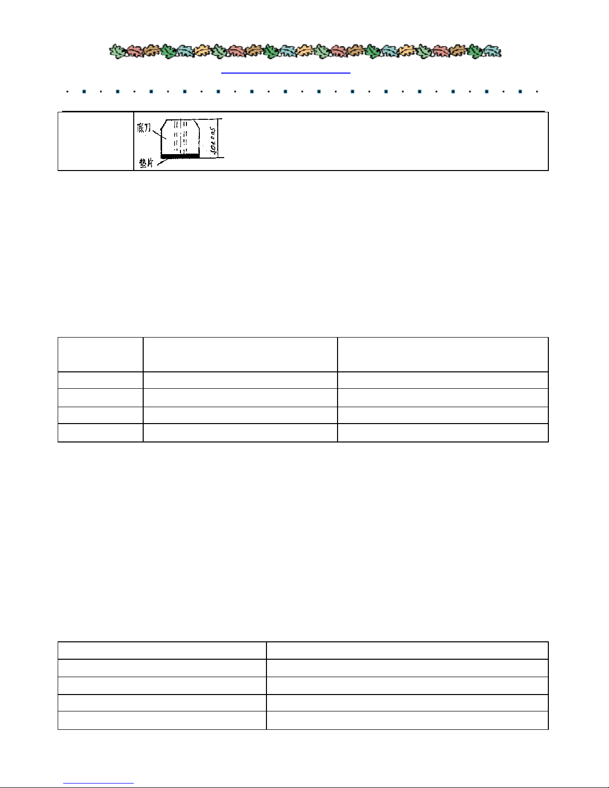
The bottom blade has 2-4 cutting edges as the following chart, once one cutting edge goes blunt, change
another cutting edge, when all cutting edges go blunt, then sharpen them. When sharpening must use the
refrigerant and guarantee the blade edge angle. If necessary, after sharpened, survey with gauge which
provide stochastically.(for example BX2113).
3) Fixed blade adjustment
PJMP218
480
130
PJMP2113
580
150
Tel:+86-18615559369 Web: www.pellet-machine-mill.com E-mail: lingfengzhuri@gmail.com
- 7 -
Need to adjust after bottom blade sharpened, the adjustment method please see the following Table 5.
Table 5
Model
Fixed BladeAdjustment Way
PJMP215
PJMP216
PJMP218
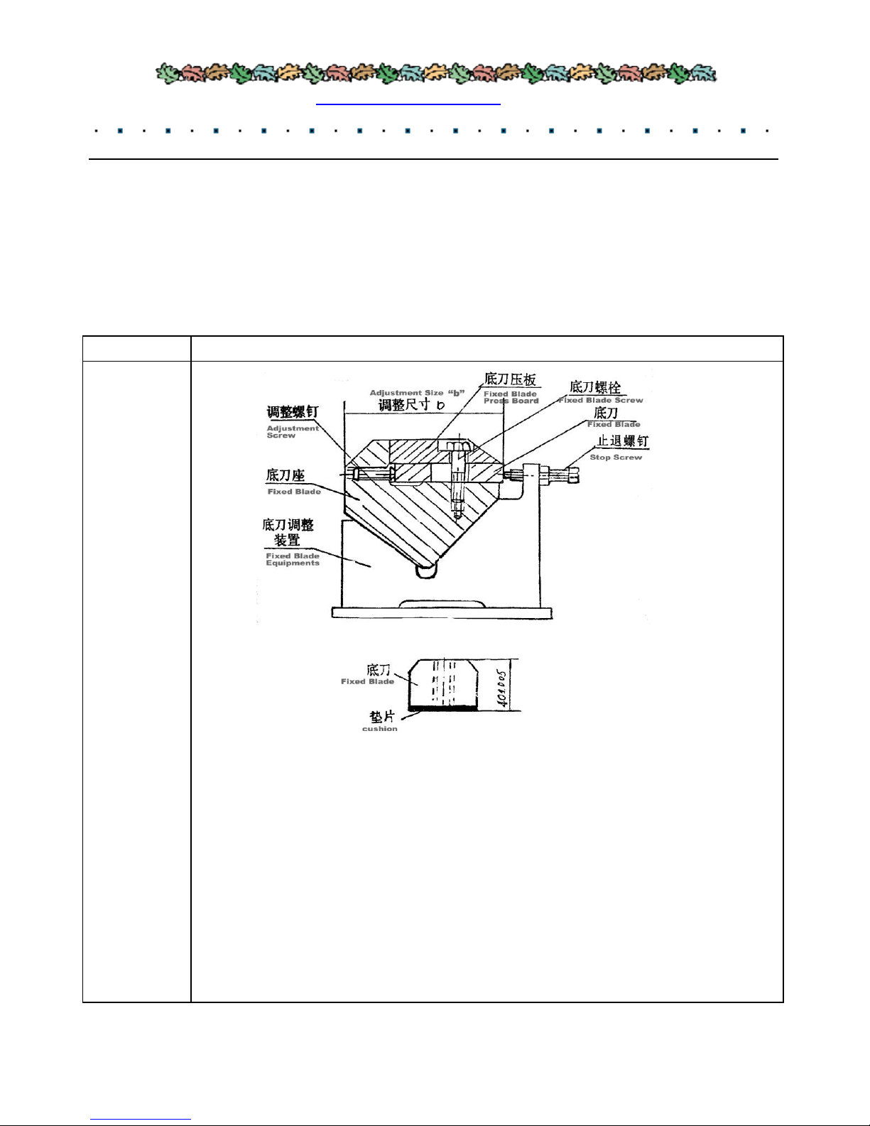
Ajusted at the fixed blade device, put the fixed blades abd the fixed blade base in the
fixed blade device, adjust the screw, make the bedge next to retreat bolt, tighten the fixed
blade screw.
Adjustment size “b” confirmation:
1. Fix the bottom blade to the base, tighten it by bolt.
2. Clean the bottom blade base, and push it into supporting.
3. Check the space between fixed blade and rotary blade whether 0.5-1mm, by the caliber
gauge. If not, adjust the screw to get it. So this szie “b” is the fixed blade size, adjust the
fixed blade based on it.
4. Size “b”does not change once confirmed, but when the blade roller reset, this zie
shoule be adjusted again.
Tel:+86-18615559369 Web: www.pellet-machine-mill.com E-mail: lingfengzhuri@gmail.com
- 8 -
4) Assemble of fixed blade
A. Tighten adjusted fixed blade and base with bolt. The bolt fasten force and the torque wrench adjustment
value sees the table 6.
B. Clean the fixed blade and daub the suitable amount lubricating oil, pushit to bottom blade base’s
supporting on the machine base.
C. Fill the clamp key after oiled, and screw the bolt on both sides simultaneously or alternately, and
tighten it.
Table 6
Model
bottom blade bolt tight moment of force
N.M
Torsion wrench adjustment value N.M
PJMP215
98
98
PJMP216
98
98
PJMP218
120
120
PJMP2113
355
300
3. The blade roller, feed roller and supporting roller’s bearing base installation
(1) Fixedend bearing installation (the end to belt pulley or reducer)
A. Install bearing base on machine base wall plate, tighten by bolt.
B. Install bearing , tightened bush, gasket and round nut on the axel and fasten round nut. When fastening,
check and adjust the space between bearing outer ring and roller to be within the stipulation scope on the
following Table.
C. Fill lubricant reach 1/4 room space (lubricant is lithium lubricant grease)
D. Install the paper gasket, bearing cover, tighten bolt.
Table 7
Model
Bearings radial space (mm)
PJMP215
0.06-0.0
PJMP216
0.06-0.09
PJMP218
0.065-0.1
PJMP2113
0.07-0.11
PJMP2113
Fill up adjusting shim same thick as sharpening quantity under the
bottom blade (provide along with the machine), guaranting that the
bottom blade and the filling piece thick is 40±0.05 millimeter.

Tel:+86-18615559369 Web: www.pellet-machine-mill.com E-mail: lingfengzhuri@gmail.com
- 9 -
(2)Moving end bearing base installation
A. Bearing base installs in machine base wall plate, fix the bolt, not tighten, keep the distance between
bearing base and wall plate 2mm, then according to the fixed end method to load bearing, tightened bush,
gasket, retreat bolt and round net, then tighten.
B. Fasten the bearing base and fix the bolt.
C. Fill lubricant reach 1/4 room space.
D. Install the paper gasket, bearing cover, tighten bolt.
4. Locking equipment assembling and dismantling
Locking equipment is used for joint blade roller andaxel, feed roller and axel.
1) Assembly sequence
①Clean the locking equipment and placed axel and the hole surface, add little grease (DONOT use grease
including disulfidized aluminum).
②Push locking equipment covering axel, then push into the hole base.
A. Tighten until feel there is slight resistance by hand, this step is very important, decides the proper
alignment.
B. Use wrench.tighten the bolt in the turns of diagonally chiasmus.
C. Then tighten whole as the step above.
2)Disassembling sequence
A) Loosen tightened bolt, stick lightly cover, so the circle will be loose.
B) If the outer and inner circle still grip, screw four bolts into the screwing holes in inner circle, force the
outer circle down.
5. The sieve disassemble and installation
(1) Disassemble
A. Loosen cover bolt and take down the cover
B. Loosen clamp bolt and take down the clamp.
C. Loosen the fragment pole bolt and take down the fragment pole.
D. Take out the sieve
(2) The sieve assembly sequence and the disassembly sequence is opposite.
VI. Hydraulic press cushion system
1. Open cover
When blade roller stops completely, loose the second fixed bolt on the cover. Open cut-off valve on the

Tel:+86-18615559369 Web: www.pellet-machine-mill.com E-mail: lingfengzhuri@gmail.com
- 10 -
small oil cylinder, and close cut-off valve on the big oil cylinder. Start oil pump to put oil into small oil
cylinder until the cover open. Close the cut-off valve after hooking.
The cover dropping speed can be adjusted oil pump’s switch knob or throttle valve. The cover dropping
should be slow and steady.
2. Adjust the upper feed roller pressure
Feeding raw materia different, upper feed roller (pendulum) pressure should be adjusted accordingly.
When cutting the small round wood or big material, the upper feed roller pressure is smaller (i.e enter
flowing oil pressure to cylinder smaller). Contrariwise, when cuts smaller material, board or waste board,
the upper roller pressure is bigger (i.e enter flowing oil pressure to cylinder bigger).
When chipper working, enter stated oil pressure through oil pump (shows in Table 8).
A) When the pressure is lower than needed, open the cut-off valave on the big oil cylinder, start the oil
pump to supply the oil. When pressure achieves needed data(on pressure gauge demonstration), then close
the cut-off valve.
B) When pressure is higher than needed, open the cut-off valve, place the oil pump switch to the oil
discharge position, cylinder’s pressure can be lower.
3. Accumulator’s function
Accumulator has both storing up energy and release shock functions.
when wood chipper working, the cut-off valve should be closed. When the “pendulum” lifts, the
accumulator discharge to the cylinder. When “the pendulum” drops, the oil returns to the accumulator
from cylinder.
Because there are certain pressure nitrogen in accumulator which plays cushioning effect, thus the
“pendulum” drop steadily and no impact.
The nitrogen pressure entering accumulator is according to Table 8.
Table 8
Model
Nitrogen pressure enter (Pa)
Oil pressure enter (Mpa)
PJMP215
1
1.3
PJMP216
1.2
1.6-1.8
PJMP218
2
2.7-3
PJMP2113
2.5
4.5-5
4. The speed of “pendulum” is controled by unilateralism cut-off valave. It should be slow drop, but no
stop.
5. The Accumulator can be taken down after all the oil pressure discharge whole.

Tel:+86-18615559369 Web: www.pellet-machine-mill.com E-mail: lingfengzhuri@gmail.com
- 11 -
VII. Electric Control
1. Main motor overload protection
The main motor starts through”Y-△”transferring switch, there is overload protection in the lines, when
overload operation, automatic turn off the circuit will work.
The main motor’s overload protection is controlled by heat relay. When the main driving motor’s current
surpasses the rated data and continues for a certain time, the alarm can sound the warning. Once this things
omes, make sure to stop feeding system and reverse, withdrawing the raw material, eliminate trouble, then
start the feeding system to continue.
2. Interlock condition
When the control push-button dials in “the link” position, the machine is at the interlock condition. At this
time, only the main motor operates, the feed motor can work. If the main motor stops, the other motors
will stop expect thedischarge motor working.
When wood chipper works normally, two feeder motors and conveyor motors ( shaking groove motor)
working together.
When material blocks (machine alarms), feeding system stop and need to back up, two feeder motors and
conveyor motor reverse together ( shaking groove in stop condition).
3. Feed motor starting
Feeding system transmission motor’s stop and restart are controlled by current reply, it depends on main
transmission motor’s load size.
When surpassing the finite current, the relay makes the feeding motor stop, and makes the supporting
feeding belt stop through interlocking equipment. When current dropping the limitation value data, the
relay operates, the feeding motor restarts, the process is automatic.
When feeding system need to back up, must firstly press the “stop” button,, when feeding system stops,
then press the “back up” switch.
4. “Pendulum” upper limit switch
when feeding height is too high to make the “pendulum” lift and surpasse stipulated limit of Table 9, the
limit switch will be touched so that the feeding system will stop. After pressing down “reverse” button,
feeding system will reject material backwards. After “pendulum” drops, the limit switch reposition, and
the limit circuit will be on. Press “FWD” button again, feeding system will continue to supply material.
Table 9
Model
“pendulum” upper limit
height mm

Tel:+86-18615559369 Web: www.pellet-machine-mill.com E-mail: lingfengzhuri@gmail.com
- 12 -
Attention: The limit switch installation position can
not change at will.
5. Emergency Stop Botton
There is an emergency stop button on machine base wall and control cabinet outside, when emergency
case comes, please press this button, the machine will stop operation.
VIII. Lubricating System
1. The blade roller, feeding roller, supporting roller, bearing on pendulum shaft need disassemble and clean
and exchange new lubricant, after half an year working. The blade roller bearing lubricant is the lithium
base lubricant, the other bearings can use ZG2 or the ZG3 lubricant.
2. The chain link in the feeding system after working 2000 hours, must be cleaned. When normal work, it
should be added lubrication regularly.
3. The belt conveyer supporting roller bearing should regularly lubricate, the lubricant trademark is ZG2
or ZG3.
4. The decelerator's oil level should maintain certain altitude, may observe from the oil gauge, upper
decelerator's oil level is on the upper oil gauge middle line, nether decelerator’s oil is on the nether oil
gauge middle line. Decelerator's oil should the periodic inspected, added or exchanged.
5. Electric motor maintenance refer to related instructions.
IX. Attention Points During Operation
1. The big input size can fit for many kinds of raw materials, such as the crooked branches, plank or the
bundle of small batten and so on. But DONNOT put the heavy log in section on it because of the big
feeder, otherwise it will damage the blade and machine.
The biggest diameter or the sectional area of input materials, please see Table 10. When near to the biggest
diameter in section, the cut wood chips can’t surpass 2m.
The moisture of cutted raw material had better at 40%.
Table 10
Model
Cut Total Diameter in
Section (cm2)
Diameter of Single Log(cm)
PJMP216
180
PJMP218
225
PJMP2113
400

Tel:+86-18615559369 Web: www.pellet-machine-mill.com E-mail: lingfengzhuri@gmail.com
- 13 -
PJMP215
≤86.5
≤10.5
PJMP216
≤110
≤12
PJMP218
≤200
≤16
PJMP2113
≤420
≤23
2. When tighten the blade, please make sure to use the torsional spanner which can concretely show the
torsional spanner and increased torsional equipment (along with this machine).
3. When tighten the fixed blade, please make sure to use the torsional spanner which can concretely show
the torsional moment.
4. The tightening bolts of the rotary blades and fixed blades must be adopt the special high-strong bolts
supplied by us ( which top of bolt shows the ZL). DOONOT use the common bolts. The lifetime of
high-strong bolt is one year, PLEASE change all by new ones after one year.
5. The rotary blade change must be in sets. When sharpening the blade edge, two rotary blades sharpeded
qutity should be the same, make sure the weight of two blade is consistent, avoid unnecessarily shaking.
When deliveried, two rotary blades have been matched already. If found blades confused, please weight
and match them again. Please pay more attention to each set of rotary blades, make sure the different
weight between these two blades less than 25 gram.
6. When the rotary blades and fixed blades sharpening, pelase add the refrigerant, otherwise the blade
edges will be wicked because of too hot or curled, causeing the durability of blade reduced. Generally
speaking, the rotary blades should sharped every one or two shift. After rotary blades changed four times,
please take out the fixed blade and do these two things: check the fixed blades if necessary to change the
cutting edge; Lubricate contact surface of fixed blade base.
7. When the nitrogen pressure in accumulator is lower than the regulated value in Table 8, please fill the
nitrogen. Please check the pressure and air filled by the aerated tool.
Note: Please aerate the nitrogen to accumulator, DONNOT aerate the oxygen or air, otherwise will lead
to explode. Details should be acted according to the description of manufacturer. When aerating the
nitrogen by the nitrogen bottle directly, the switch should open slowly, prevent the high-pressure nitrogen
enter into bottle and damage gallbladder.
8. Electric apparatus should be checked termly, make sure the correct action of them, avoid the
unnecessary damage.
9.When the machine chips overload, the operation current should not surpass the rated current (the
instantaneous overloading is permitted).

Tel:+86-18615559369 Web: www.pellet-machine-mill.com E-mail: lingfengzhuri@gmail.com
- 14 -
10. When start the machine, please start the motor of discharging materials system first, then start the main
motor. When the blades rollers work stably, start the feeder motor. When stop the machine, please close
the feeding system first, after the blade rollers can’t cut the wood, close the main motor. Please
DONNOToverturn the upper order.
11. Please check and maintain the machine after working per shift, especially check the tightening bolts
outside firm or not, the hydraulic pressure systemwork well or not. Examine all the bolts per month.
12. Checked parts of this machine in the breaking-in period should refer to the upper feeding rollers(-)
X. Main spare parts
1. Blades
Items
Name
Model
Code in drawings
1
Rotary blade
PJMP215
B18·2-4
PJMP216
B 12·2-12
PJMP218
PJMP218·02·300-01
PJMP2113
B36·2-10
2
Fixed blade
PJMP215
B18·1·3-2
PJMP216
B12·1·3-2
PJMP218
PJMP218·01·400-02
PJMP2113
B33·1-13
3
Sieve
PJMP215
B18·1·2
PJMP216
B12·1·2
PJMP218
PJMP218·01·200
PJMP2113
B36·1·2
4
Base of fixed blade
PJMP215
B18·1·3-3
PJMP216
B12·1·3-2
PJMP218
PJMP218·01·400-03
5
Rotary Blade Bolts
PJMP215
B36·2-13
PJMP216
PJMP218·02-10
PJMP218
PJMP2113
PJMP36·2-13
6
Fixed blade Bolts
PJMP215
PJMP218·01·400-04
PJMP216
PJMP218
PJMP2113
B36·1-12

Tel:+86-18615559369 Web: www.pellet-machine-mill.com E-mail: lingfengzhuri@gmail.com
- 15 -
2. Bearing list
Item
Name
Model
Bearings model
Qty
1
Bearing of Blade Roller
PJMP215
113524
2
PJMP216
113524
2
PJMP218
113530
2
PJMP2113
3113736 import model:23136SKMB
2
2
Bearing of feeding roller
PJMP215
113516
6
PJMP216
113516
10
PJMP218
113518
12
PJMP2113
3113722 import model:23122K·MB
18
3
Bearing of supporting
roller
PJMP215
113515
2
PJMP216
PJMP2113
113518
2
4
Bearing of Reducer
PJMP215
PJMP216
PJMP218
32309
2
3056308
2
7508
4
220
4
PJMP2113
5
Bearing of Belt
Conveyor Driven
(Or shaking groove)
PJMP215
90515
2
PJMP216
PJMP218
GBX2113
90516
2
6
Bearing of Tighting
Roller in Belt
PJMP215
90512
2
PJMP216
PJMP218
PJMP2113
90514
2
7
Bearing of supporting
roller in belt conveyor
PJMP215
C0108
2
PJMP216
This manual suits for next models
3
Table of contents
Popular Chipper manuals by other brands

EMB
EMB Wallenstein CR Series Operator's manual
 Specifications")
Echo
Echo SC5670B (75524) Specifications

Echo
Echo Bear Cat CH922DH owner's manual

Farmi Forest
Farmi Forest CH10 OPERATION, MAINTENANCE AND SPARE PARTS MANUAL

Farmi
Farmi 381 HFC OPERATION, MAINTENANCE AND SPARE PARTS MANUAL

Troy-Bilt
Troy-Bilt CS4265 Operator's manual

Billy Goat
Billy Goat Termite KD512SP Operator owner's manual

DK2 Power
DK2 Power OPC505AE Assembly guide

Farmi Forest
Farmi Forest CH180 AVANT Operation and maintenance manual

Farmi Forest
Farmi Forest FARMI 260 OPERATION, MAINTENANCE AND SPARE PARTS MANUAL

Bearcat
Bearcat 71020 owner's manual

Forest-Master
Forest-Master FM13WC user manual


