71020 & 70554 Chipper Shredder Owners Manual Page 5
Safety
1.6 BATTERY SAFETY
1. Improper use and care of the at-
tery on electric start models can
result in serious personal injury or
property damage. Always o serve
the following safety precautions:
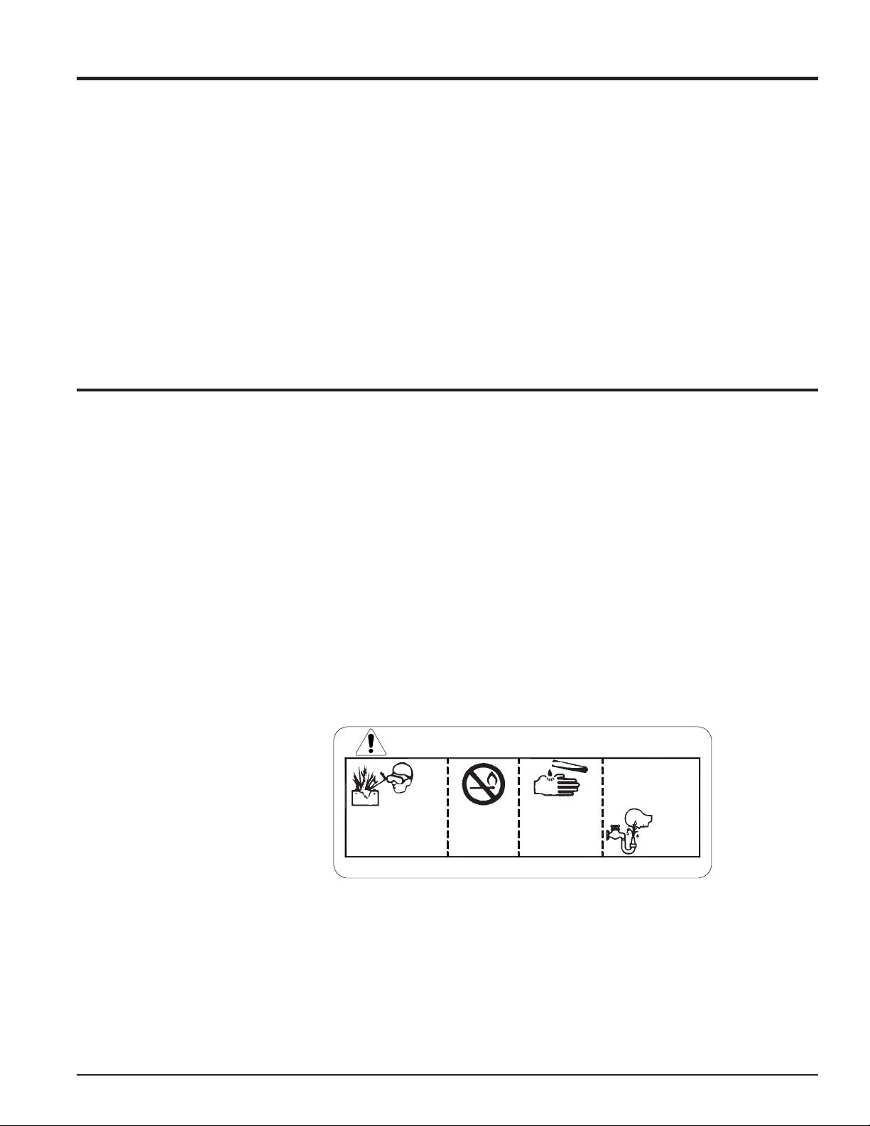
A- Poison/Danger - Causes Severe
Burns. The attery contains sulfu-
ric acid. Avoid contact with skin,
eyes or clothing. Keep out of
reach of children.
ANTIDOTE-External Contact:
Flush immediately with lots of wa-
ter.
ANTIDOTE-Internal: Drink large
quantities of water or milk. Follow
with milk of magnesia, eaten egg
or vegeta le oil. Call a physician
immediately.
ANTIDOTE-Eye Contact: Flush
with water for 15 minutes. Get
prompt medical attention.
B- The attery produces explosive
gases. Keep sparks, flame or
cigarettes away. Ventilate area
when charging attery. Always
wear safety goggles when work-
ing near attery.
C- The attery contains toxic materi-
als. Do not damage attery case.
If case is roken or dam-aged,
avoid contact with attery contents.
Neutralize acid spills with a ak-
ing soda and water solution. Prop-
erly dispose of a damaged or worn-
out attery. Check with local au-
thorities for proper disposal meth-
ods.
D- Do not short circuit attery. Se-
vere fumes and fire can result.
E- Before working with electrical wires
or components: disconnect at-
tery ground (negative) ca le first.
Disconnect positive ca le second.
Reverse this order when reconnect-
ing attery ca les.
DANGER / POISON
SHIELD EYES
EXPLOSIVE GASES
CAN CAUSE
BLINDNESS OR
INJURY
NO
• SPARKS
• FLAMES
• SMOKING
SULFURIC
ACID
CAN CAUSE
BLINDNESS OR
SEVERE BURNS
FLUSH EYES
IMMEDIATELY
WITH WATER
GET
MEDICAL
HELP
FAST
KEEP OUT OF THE REACH OF CHILDREN. DO NOT TIP. KEEP VENT CAPS TIGHT AND LEVEL.
1.5 TOWING SAFETY
1. Rotate the discharge tu e to face
the opposite direction of the tow-
ing vehicle efore towing. This pre-
vents the discharge tu e from pro-
jecting over the trailer wheels and
striking foreign o jects.
2. Connect hitch safety chains.
Tighten and secure trailer hitch
olts. Do not attempt to tow the
trailer if vehicle is not equipped with
a 2 all.
3. Do not exceed maximum towing
speed, indicated on tire sidewall.
Inflate tires to manufacturers specs
as stated on the tire sidewall.
4. Check wheel lug olts periodically
to ensure they are tight and se-
cure.
5. Make sure the jack stand on trailer
is in the UP position to clear the
ground during towing. Place the
jack stand on a level surface and
secure it in the DOWN position e-
fore use.
6. Never allow passengers to ride on
the chipper chute while the vehicle
is moving, whether the chipper is
running or not.
7. If applica le, shut off fuel supply
when towing.