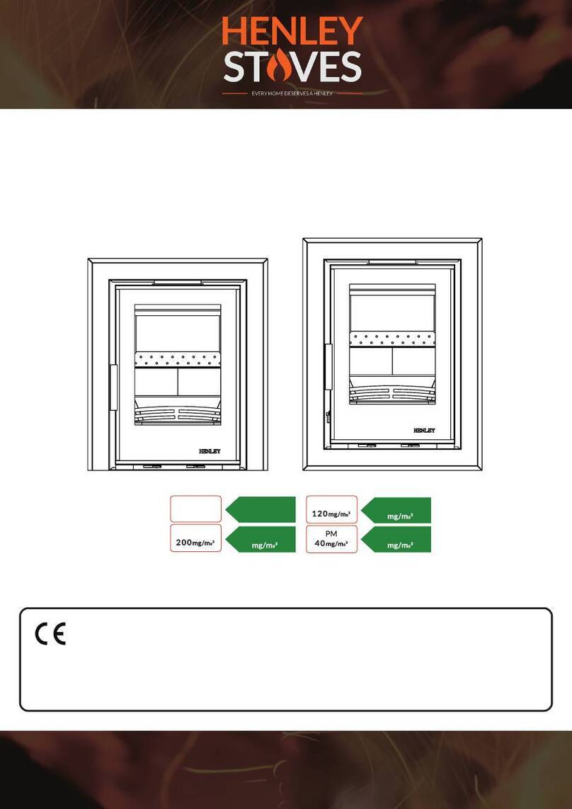
Henley Stoves ECO C550 Manual

1
ECO C550
Cassette Room Heater Stoves
THE HEATING SPECIALISTS
“Every Home Deserves a Henley”
0.12%
CO
NOx
CxHy
%
0.06
110
56
29
IMPORTANT!
Our stoves must be tted by a HETAS/METAC Qaulied Installer.
Only Burn Recommended Fuels with this Stove
Installation & Operating Instructions

2
Index
How to register your new stove:
Henley Stoves does not accept warranty submissions
through post/email. Please register your warranty at
https://henleystoves.com/warranty/
See page 22 of this Manual for full details on
Warranty Terms & Conditions.
HENLEY STOVES WARRANTY
Congratulations on the purchase of your New Henley Stove!
With the proper care & attention your Henley stove will give you a lifetime of heat & comfort.
This manual contains instructions on how to install and maintain your Henley Stove.
For both your comfort & safety please take the time to read instructions carefully.
1. Technical Information
2. Stove Commissioning Checklist
3. Installation Instructions
Hearth
Ventilation
Chimney
4. Flue Positions
Height Over Adjacent Building
Height Over Roof
Height Over Openings
5. Flue Options
Flue Options - Top/Rear
Flue Options - Diagram
6. Installation Requirements
7. Non-Combustible Materials
8. The Clean Air Act 1993
9. Combustible Materials
10. Recommended Fuels
11. Lighting The Stove
Re-fueling
Refueling On To A Low Fire Bed
Fuel overloading
Operation With Door Left Open
Dampers Left Open
3
4
5
6
7
7-8
8
9
9
9
10
10
10
11-12
13
13
13
13
14
15
15
15
15
15
12. Shutting Down Stove
13. Maintenance
BaePlate
Chimney Sweeping
Removing The Ash-pan
Replacing Fire Rope
ReplacingBaePlate
Replacing Stove Door Glass
Removing The Fuel Retainer
14. Air Controls
15. Useful Information
16. Stove Finish (Paint)
17. Chimney Fire & Over-ring
18. Carbon Monoxide Alarm
19. Spare Parts
20. Product Fiche
21. FAQ’s
Annual Service
Seasonal Use
Ventilation
21. Terms & Conditions
15
15
15
15
16
16
17
17
17
18
18
19
19
19
20
21
22
23
23
23
24

3
Technical Information
Eco C550 (3 side trim)
Eco C550 (4 side trim)
Specications
MODEL Eco C550
CONFIRMS TO EN13229
DIMENSIONS H: 538/594mm W:663mm D:344mm
WEIGHT 96 KG
FLUE SIZE 127mm
ERP RATING A
ENERGY INDEX 101
FUEL WOOD
HEAT OUTPUT 6.9kW
EFFICIENCY 75.8%
EMMISSIONS CO AT 13% O20.06%
662.5
593.5
442
506
100
482
550
343.5
95
127
662.5
537.7
442
506
100
482
550
343.5
95
127

4
Please complete the form below as it will be of great assistance in the
highly unlikely event that there is a problem with the stove or a warranty
claim needs to be made. Please contact the person who installed the stove
or the dealer where it was purchased from if there is a problem.
Dealer Appliance Was Purchased From
Essential Information - MUST BE COMPLETED
Installation Engineer
Commissioning Checks (to be completed and signed)
Name:
Address:
Phone:
Date installed:
Model Description:
Serial number:
Company name:
Address:
Phone:
Stovecorrectlyuedaccordingtobuildingregulations:
Fluesweptandintegrityofueveried:
Smoke test completed on installed stove:
Spillage test completed:
Use of appliance and operation of controls explained to end-user:
Checkthatspeciedclearancetocombustibleshasbeenadheredto:
Instruction manual handed to end-user:
HETAS Approved (Please tick relevant box): Yes No IfYes,pleaseincludecerticateofcompliance.
Yes No
Yes No
Yes No
Yes No
Yes No
Yes No
Yes No
Signature:Print name:
Stove Commissioning Checklist

5
Installation Instructions
Installation
Before installation and/or use of this appliance
please read these instructions carefully to ensure
that all requirements are fully understood. The
appliancemustbettedbyaregisteredinstaller*,
orapprovedbyyourlocalbuildingcontrolocer.
Regulations
Please refer to the current issue of
British Standard BS 8303, Code of Practice
for Installation of domesting heating
appliances burning solid fuel, Building
Regulations, Local Authority Bylaws and other
specicationsorregulationsincludingIreland,
UKorEUstandardsreferredtoastheyaectthe
installation of the stove.
Building regulations available on www.environ.ie
& www.planningportal.gov.uk.
Domestic Heating
Only use for domestic heating in accordance with
these operating instructions.
Fuel
Only approved fuels must be burned.
Do not use liquid fuels or as an incinerator.
Fireguard
Appliance surfaces become very hot when in
use.AreguardconformingtoBS8423:2010
should be used in the presence of children, the
elderlyorinrm.
Please note, this appliance should be used with
theredoorclosedatalltimesexceptwhen
fueling, cleaning ash or initial lighting.
Combustible Materials
Do not place photographs, TV’s, paintings,
porcelain or other combustible items on the
wall or near the appliance. Exposure to hot
temperatures will cause damage. Do not place
furniture, or other items such as drying clothing,
closer than 1 metre from the front of this
appliance. Do not use aerosol sprays or any other
ammablematerialsneartheapplianceunderre.
Asbestos
This stove contains no asbestos. If there is a
possibility of disturbing asbestos in the course of
installation then please seek specialist guidance
& use appropriate protective equipment.
Fire Cement
Sometypesofrecementarecausticand
should not be allowed to come into contact
with the skin. In case of skin contact, wash
immediately with plenty of water.
Extractor Fan
It is possible to install this appliance in a kitchen
or open plan room which uses an extractor fan.
Adequate provisions must be made, as the
extractor will draw air from the room. A draught
test needs to be carried out on the appliance
with the extractor fan running on full power.
Based on results from the draught test, extra
ventilation should be added where necessary.
Ventilation:
Do not obstruct inside or outside ventilation
required for the safe use of this appliance.
Alterations
Do not make unauthorized changes to the
appliance.
Chimney
The chimney must be swept at least once a
year.
Flue System
Donotconnect,orshare,thesameueor
chimney system with another appliance.
Serial Number
The serial number is required when ordering
spare parts or making warranty claims. It is
found on the appliance data plate.
Manual Handling
Before continuing any further with the
installation of this appliance please read the
following guide to manual handling.
• Always obtain assistance when lifting
• When lifting always keep your back straight
• Avoid twisting at the waist. It is better to
reposition your feet.
• Avoid upper body/top heavy bending. Do not
lean forwards or sideways
• Always grip with the palms of your hands do not
useyourngertipsforsupport,useglovesfora
better grip
• Always keep the stove close to the body as this
will minimize the cantilever action.

6
Hearth
g.1 Constructional Hearth Dimensions
for Solid Fuel Appliances & Open Fires
Hearths should be constructed from suitably
robust materials & to appropriate dimensions.
(g.1)
A way of making provision would be to adopt
the guidelines outlined below & to provide a
hearth appropriate to the temperatures that the
appliance can create around it.
The hearth should be able to accommodate the
weight of the appliance & it’s chimney if the
chimney is not independently supported.
Consult a structural engineer for advice before
proceeding.
Ifthereisnoexistingreplaceorchimneyitis
possible to construct a suitable non-combustible
housingandhearthsetting.Theuemustbe
installed in accordance with all local and national
regulations and current rules in force.
Check if adding a new chimney to your property
requires planning permission.
The Stove should be installed on:
B. Constructional hearths in accordance with the
guidelines outlined. (g.2)
Constructional Hearths should have dimensions
asoutlinedingure1above.
They should be made of solid, non-combustible
such as concrete or masonry, at least 125mm
thick, including the thickness of any non-
combustibleoorand/ordecorativesurface.
g.2 Non Combustible Hearth
surrounding Solid Fuel Appliance
g.3. Ways of Providing Hearths

7
Ventilation
Ventilation
This appliance requires a constant supply of air
tomaintainpropercombustionandeectiveue
performance.
An inadequate air supply can result in poor
combustion and smoke entering the room which
is potentially dangerous.
An Extrernal Air inlet must be tted for this
stove.
The amount of air required must comply with
local building regulations and the rules in force.
Chimney
Please refer to the current issues of
British Standards BS EN 15287-1:2007 -
design,installation and commissioning of
chimneys before commencing installation
The chimney draw is critical on any installation
and should be checked to ensure that it matches
whatisspecied.Ifthedrawishigherthan
recommended, we advise that provision must be
made to correct the overdraw. The draw can vary
indierentweatherconditionsandthecustomer
should be made aware of this. Failure to correct
anover-drawinguewillinvalidatethewarranty,
and may damage the appliance.
Please remember that chimney draught is
dependent on four main factors.
• Flue gas temperature • Flue height • Flue size
• Flue terminal
Theueorchimneysystemmustbeingood
condition. It must be inspected by a HETAS
QualiedInstallerandpassedforusewith
the appliance before installation. Products of
combustion entering the room can cause serious
health risks.
The following must be checked:
• The construction of the masonry chimneys,
ueblockchimneys&connectinguepipe
system must meet requirements of the Building
Regulations.
Werecommendaexibleuelinersystem
certiedforusewithsolidfuelsystemsbeused
toimprovestoveperformance.Theueliner
must be removed when an appliance is replaced,
unless proven to be recently installed and in
good condition.
Ifitisnecessarytotaregisterplateitmust
conform to the Building Regulations.
•Theminimumheightoftheueorchimneymust
be4.5mfromthehearthtothetopoftheue,
with no horizontal sections & a maximum of 4
bends. Bends must have angles of less than 45
degrees from the vertical.
Ensuretheconnectinguepipeiskeptasuitable
distance from any combustible material and does
not form part of the supporting structure of the
building.
Make provision to remove the appliance without
the need to dismantle the chimney.
Anyexistinguemustbeconrmedassuitable
forthenewintendeduseasdenedinthe
Building Regulations.
Theueorchimneysystemsmustbeinspected
andswepttoconrmthesystemisstructurally
sound and free from obstructions.
If the chimney is believed to have previously
servedanopenreitmustbesweptasecond
time within a month of regular use after
installation to clear any soot falls that may have
occurredduetodierenceincombustionlevels.
Theueexitfromthebuildingmustcomplywith
local building control rules.
Donotconnectorsharetheueorchimney
system with another heating appliance.
Do not connect to systems containing large voids
or spaces over 230mm square.
EXTERNAL AIR
External air Inlet must be
tted for this stove

8
Suitable access must be provided to enable the
collection and removal of debris.
Theuemustbesweptandinspectedwhenthe
appliance is installed.
Theuedraughtmustbecheckedwithall
windows and doors closed and any extraction
fans in this, or adjoining rooms, running at
maximum speed (see next section for additional
ventilation requirements).
• Max. draught = 2.0mm Wg,
• Min. draught = 1.0mm Wg
Chimney
C
B
D
A
Horizontal
Measurement
Terminal
Flue
Vertical
Measurement
Insulation
150mm
Max
Seek specialist advice if installing
in a dwelling with a thatched roof
The datum for vertical measurement is the point of
discharge of the flue from either the point of disxcharge
ofn the flue or 150mm above insulation, whichever is
the lower.
Adjacent
Building
Adjacent
Building
These positions are defined by Document J of the Building Regulations.
Flue Positions
C
B
D
A
Horizontal
Measurement
Terminal
Flue
Vertical
Measurement
Insulation
150mm
Max
Seek specialist advice if installing
in a dwelling with a thatched roof
The datum for vertical measurement is the point of
discharge of the flue from either the point of disxcharge
ofn the flue or 150mm above insulation, whichever is
the lower.
Adjacent
Building
Adjacent
Building
These positions are defined by Document J of the Building Regulations.
Pointwheretheuepassesthroughweathersurface(Note1&2) Clearancestotheueoutlet
A At or within 600mm of the ridge At least 600mm above ridge
BElsewhereontheroof(whetherpitchedorat) At least 2300mm horizontally from the nearest point on
the weather surface (a) at least 100mm above the highest
point of interaction of the chimney and weather surface; or
(b) at least as high as the ridge
C Below (on a pitched roof) or within 2300mm horizontally to open-
ablerooight,dormerwindow,orotheropening(Note3)
At least 1000mm above the top as the ridge
D Within 2300mm of an adjoining or adjacent building, not beyond the
boundary (Note 3) At least 600mm above any part of the adjacent of the
building wall
Note:
1. The weather surface is the building external, such as it’s roof tiles or external walls.
2.Aatroofhasapitchlessthe10º
3. The clearance given forA or B, as appropriate, will also apply.
4.Averticaluexedtoanoutsidewallshouldbetreatedasequivalenttoaninsideueemergingatthenearestedgeoftheroof
WARNING
Under no circumstances should
this appliance be connected to
a shared ue system, that serves
any other heating appliance.

9
Height Over Adjacent Building
TheOutletofachimneyorueinrelationtoanadjacentbuildingshouldbeasseenabove
Height Over Roof
Outletofachimneyorauetobenotlessthat1mabovethehighestpointofcontactofchimneyandroof.
Wheretheroofhasapitchofmorethan10ºonbothsidesandtheoutletisattheridgeorwithin600mmofit,
theheightofthechimneyoruepipemaybereducedto600mm.
Height Over Openings
Theoutletofachimneyoruepipeshouldalsobenotlessthan1mabovethetopofanyopeningskylight,
opening window or wall ventilator within 2.3m

10
Flue Options
Each installation is unique to the property so it is
not possible to give details to suit every setting.
The installation must comply with Building
Regulations and be made using best practice
construction methods.
Manyreplaceopeningshaveasupportinglintel.
Do not remove without supporting the remaining
structure of the building.
Do not support the structure with the appliance
ortheuesystem.
Take care when installing the appliance.
Careless handling and use of tools can damage
thenishand/orarea.
Choosetopueexitandtuecollartosuit
installation.Sealwithrecement.
Flue Options - Top
Flue Options - Diagram
External Air
WE RECOMMEND
Flexi-Liner is Used for
Maximum Eciency
air supply using suitable adapter.
Flue Outlet
(top of stove)
External air inlet
(rear of stove)
An extrernal Air inlet must be tted for this
stove.Theairductisttedontothestovearound
the air inlet and is fed from the supply tube on
the rear face of the duct assembly.
Theexiblepipingshouldbetakendirectlytoan
external wall, avoiding sharp bends or excessive
direction changes.
The piping should be terminated at the wall and
bettedwithasuitablegrilltopreventblockages
by leaves and other debris.
EXTERNAL AIR
External air Inlet must be
tted for this stove
500mm
Straight Pipe
Flexi Liner
all the way to
top of Chimney
Lined Chimney
min.
External Air
inlet
Fill space with
vermiculite

11
Stove Installation Requirements
When Installing a Henley Insert Stove there
are a number of considerations to be taken into
account before commencing installation.
When the stove is installed in a masonry
chimney, there has to be a minimum distance
of 20mm above & at the sides when the stove
frame is removed.
This is to allow for expansion due to heating
of the stove.
Failure to follow this recommendation will
render Warranty Null & Void.
We would recommend to make the opening
much larger in a masonry chimney & to close
the space by using a metal stud frame & high
temperaturere-board(see diagram opposite)
This space is required the allow for thermal
expansion when stove is lit.
Henley Stoves cannot guarantee that some
nisheswillnotdiscolorwithheatandthat
non-recommended materials or lower quality
products will not distort, or crack when used.
In order to prevent excessive heat build in the
chimney breast, manufacturer’s guidelines
should be followed in relation to adequate
distances being adhered to regarding distance
from stove to adjacent surfaces
To further prevent excessive heat build up,
Henley Stoves recommend that a hole be drilled
into the wall at the side of the chimney breast to
let trapped heat escape. (see diagram opposite)
This trapped heat can cause cracks and other
damage to the area surrounding your stove.
If you are in any doubt about any aspect of
these the installation requirements, or suitability
of construction materials, please consult your
Henley Stoves stockist or a HETAS Approved
Registered Installer.
The opening where you intend to install your
new stove should be constructed from non-
combustible materials which remain stable at
high temperatures and comply with local and
national building regulations.
Examples of typical non-combustible materials
include; aerated concrete, vermiculite & calcium
silicate.
Shouldthenishofthesurroundingareabe
smooth plaster, considerations should be given
to the conducted and convected heat emitted
by the stove. These high temperatures can be
high enough to crack and distort normal gypsum
based plaster.

12
Henley stoves recommended that a high
temperature plaster which does not contain any
gypsum is used.
After applying new plaster, it should be given
adequate time to fully dry. Failure the allow the
plaster time to fully dry can result in cracking.
Alternatively the area surrounding the stove
can be faced with a suitable high temperature
plasterboard.
As well as using high temperature plaster /
plasterboard, the area surrounding the stove
can also be dressed using granite, ceramic or
porcelain tiles.
If stone / granite / marble or any other natural
materialisusedtoconstructtheresurround,
or any part of it, considerations should be
made for expansion and movement of the
parts due to heating and cooling of the stove
and surrounding areas.
*ForIllustrationpurposesonly
It is possible for the exterior of the stove to
reach temperatures of up to 300°C / 149°F and
fortheuetoreachevenhighertemperatures.
Therefore construction materials should be not
be in direct contact with the stove and should
be given at least 25mm / 1 inch distance
from the stove which will allow for thermal
expansion. This expansion occurs naturally
during the heating and cooling of the stove.
Construction Materials

13
Under the Clean Air Act local authorities may
declare the whole or part of the district of the
authority to be a smoke control area.
Itisanoencetoemitsmokefromachimneyof
abuilding,fromafurnaceorfromanyxedboiler
if located in a designated smoke control area.
Itisalsoanoencetoacquirean“unauthorized
fuel” for use within a smoke control area unless
itisusedinan“exempt”appliance(“exempted”
from the controls which generally apply in the
smoke control area).
In England appliances are exempted by
publication on a list by the Secretary of State in
accordance with changes made to sections 20
and 21 of the Clean Air Act 1993 by section 15 of
the Deregulation Act 2015.
Similarly in Scotland appliances are exempted by
publication on a list by Scottish Ministers under
section 50 of the Regulatory Reform (Scotland)
Act 2014.
In Northern Ireland appliances are exempted
by publication on a list by the Department of
Agriculture,EnvironmentandRuralAairsunder
Section 16 of the Environmental Better regulation
Act (Northern Ireland) 2016.
In Wales appliances are exempted by regulations
made by Welsh Ministers.
Further information on the requirements of the
Clean Air Act can be found here:
https://www.gov.uk/smoke-control-area-rules
Your local authority is responsible for
implementing the Clean Air Act 1993 including
designation and supervision of smoke control
areas and you can contact them for details of
Clean Air Act requirements.
The Clean Air Act 1993 & Smoke Control Areas
Safe distances to combustible materials for the
ECO C550 should be a minimum of 20cm to the
sides, 125cm to Front and 60cm above stove.
The stove should be placed in a non combustible
hearth with a distance of 600mm to the top (non-
combustible wooden mantle top recommended)
Adjacent walls should be of suitable non
combustible construction, preferably brickwork.
Inlargereplacestakecarethatanysupporting
beam is protected by a 13mm (0.5”) thick sheet
of Masterboard / Supalux spaced 13mm (0.5”)
othesurfacewithstripsofnon-combustible
material.
Make sure that there is a gap between an un-
insulateduesystemandanycombustible
material. This gap must be at least 3x the
outsidediameteroftheuepipe,or1.5xtheue
diameter to non-combustible surfaces.
Combustible Materials
Recommended Fuels
Wood logs
- Burn only seasoned timber with a moisture
content of less than 20%. To ensure this allow cut
wood to dry for 12 to 18 months.
Poor quality timber causes low combustion
eciency,producesharmfulcondensation,
reduceseectivenessoftheairwashandlifeof
the appliance.
(This stove is Wood Burning only)
Wood length
max 200mm,
and 100mm
in diameter.

14
Lighting the Stove
We recommend that you have two or three small
resbeforeyouoperateyourstovetoitsmaxi-
mum heat output.
This is to allow the paint to cure in steadily and to
givealongservicelifeofthepaintnish.During
this curing in process you may notice an un-
pleasantsmellwhilstthenishesnallycure.Itis
non-toxic, but for your comfort we would suggest
that during this period you leave all doors and
windows open.
First, open the primary and secondary air wash
controlfully.Loadthereboxwithplentyofstart-
ingfuel,i.e.paper,drysticksand/orrelighters.
Lightthereatthebaseleavingtheprimaryand
secondary air control fully open. Leave the door
slightly ajar for 10 minutes to enhance initial
starting and reduce smoke emission – DO NOT
leave the stove unattended if the door is left
ajar.
Allow the fuel to reach a steady glow and build
thereupgraduallybyaddingafewsmallsticks
or well split logs at a time. Once you have a good
rebedestablishedacrossthegrate,furtherfuel
can be added step by step as required.
Don’tbetemptedtooverloadtherebedwith
fuel all at once or close down the air controls too
muchuntilthereisreallywellestablishedfor
some time.
Once the ignition period is well under way close
the primary air and gradually reduce the sec-
ondary air wash control opening to establish the
burning intensity you require (usually open 25%
approx.).
Refueling the Stove
Whenburningwood,therewilldiedownasthe
fuelisconsumed.Whentheamesdisappear
and the remainder is breaking down into glowing
embers it is an appropriate time to consider re-
fuelling.
Note:Iftheamesdisappearandtherearestill
lumps of solid wood left this indicates excessive
moistureinthewoodorinsucientairsupply/
uedraught.
Note: To eliminate unwanted smoke emission,
afterloadingnewlogsontothere,opentheair
wash control up fully for 1-2 minutes to boost the
reandgetamesissuingfromthetopofthe
fuelassoonaspossible.Whenamesarewell
established, reduce the air wash to the running
setting required.
Burningwithoutamesabovethefuelwillcreate
unnecessary smoke.
DO NOT load fuel above the tertiary air inlet
holes at the back of the rebox.
Loading 1 to 2 medium sized logs will produce a
good output with reasonable burn time, generally
small logs will burn up quicker producing a high
output for a short time and a large log will take
longer to burn and produce less output over a
given time.
This appliance is approved for intermittent
operation on wood (0.75 to 1.5 hour burn
cycles) although much longer burn times can
beachievedbyfullyloadingtherebox,getting
the fuel burning well and then shutting the air
controls down.
Therewillthenoftenneedrevivingbyrstde-
ashing and then using small pieces of wood and
plentyofairtogetamesissuingfromthewood
again.

15
Directly after refueling it was necessary to
operate with the secondary air fully open for
a period 3 to 5 minutes before closing to the
desired setting
When refueling the appliance it was
necessary to leave the door ajar for a period
of 1 - 2 minutes in order to sustain ames on
the newly charged fuel load.
Ifthereisinsucientburningmaterialinthe
re-bedtolightanewfuelcharge,excessive
smoke emission can occur.
Refuelingmustbecarriedoutontoasucient
quantity of glowing embers and ash that the new
fuel charge will ignite in a reasonable period.
Iftherearetoofewembersintherebed,add
suitable kindling to prevent excessive smoke
Refueling on to a low re-bed
Fuel Overloading
Themaximumamountoffuelspeciedinthis
manual should not be exceeded, overloading
can cause excess smoke.
Operation with Door Left Open
Operation with the door open can cause excess
smoke. The appliance must not be operated with
the appliance door left open.
Dampers Left Open
Operation with the air controls or dampers open
can cause excess smoke.
The appliance must not be operated with air
controls or dampers door left open except as
directed in the instructions.
The stove will remain very hot for a
considerable time after the re has died
down or been extinguished.
Petroleum coal fuels or household waste
must not be burnt in this appliance
Shutting Down Stove
The stove will normally shut down by itself as the
fuel is consumed.
In order to shut down the stove for other
reasons, close the primary air controls (if open),
then close the secondary air control.
Ifthecontrolsareleftinthisposition,therewill
eventuallyburnout.Ifyouwanttorevivethere
open the secondary air controls fully.
Inspecttheinsideofthereboxandabovethe
baeplateeveryweekduringuse.
Only use manufacturers recommended
replacement parts on the appliance.
Maintenance: Bae Plate
Maintenance: Chimney Sweeping
Sweeping should be carried out with the correct
size brush and rods to suit the chimney size and
type.
As with all appliances regular sweeping of
theueisessentialtoavoidthedangerofa
blockage and escape of poisonous fumes.
Access for cleaning should be incorporated into
the chimney (e.g. soot door, access through the
register plate etc.)
Any existing chimney should be swept prior
to installation of the stove, and then again a
second time within one month of regular use
after installation to establish the frequency of
sweeping required.

16
This should be done by and competent person
such as a NACS chimney engineer who will
provideaCerticateofChimneySweeping.
Sweepthewholeueway,includingtheoutletat
least twice a year per burning season.
Itisimportantthattheueways,uepipeand
chimneybecleanedpriortolightingthereafter
a prolonged shut-down period.
The appliance will require ash to be removed
periodically.
Ash may be removed with a small metal shovel
whilstthereisstillalight,byrakingtheembers
ofalowretoonesideofthereboxand
carefully removing the ash.
Repeating the procedure for the other side of the
rebox.Caremustbetakennottoriskburning
your hands or household objects from falling
embers.
The ash pan should be emptied at least twice a
day or when the ash reaches the top of the ash
pan.
On no account should the ash be allowed to
build up to touch the underside of the grate bars,
as this will greatly reduce the life span of the
grate.
Maintenance: Removing the Ashpan
Periodically visually check over the door rope
seal for any damage, cuts or tears and detached
sections.
The rope gasketing can be replaced, using a
universal roping kit.
Instructions for rope replacement are as follows:
• Ensure the appliance is cold
• Unscrewthehingesandliftthedoorothe
applianceandlayontoaatsurfacewiththe
rear face upwards
• Carefully remove the old rope gasket and old
adhesive.
• Take note of the layout of the rope seal.
Ensure no traces of the old adhesive or rust /
akypaintispresent,asthiswillresultinan
unsound joint.
• Apply the rope adhesive following the
instructions on the bottle
• Press the rope gasketing into the channel
on the rear door casting, following the same
layout as the old rope seal.
• Justbeforethenalend,cuttheropesealto
length and glue into positio.
• Allowatleast30minutesbeforerettingthe
door to the appliance.
Maintenance: Removing Fire Rope
Stove Rope

17
Maintenance: Replacing Bae Plate
Maintenance: Replacing Door Glass
In the event of the door glass being broken it can
easily be replaced using the following procedure:
• Ensure the appliance is cold.
• Liftthedoorotheapplianceandlayontoa
atsurfacewiththerearfaceupwards.
• Unscrewthefourscrewxingssecuring
the glass clips and remove both clips, and
xings.
• Carefully remove any pieces of broken glass
and sealing gasket. Wear suitable gloves for
this procedure. Take note of the position and
joint of the rope gasket.
• Replace the rope gasket, remove the self
adhesive backing on the rope as you go, start
at the bottom of the window, centrally. Push
the adhesive side of the rope into the grove
on the rear of the door casting gradually work
your way round until the ends of the rope
meet.
• Re-seat the new glass, ensuring the glass
sits fully against the gasket.
• Replacethefourretainingclipsandxing
screws.Donotovertightenthexingsas
damage may occur to the glass.
• Retthedoorassemblybackontothestove,
carefully lift the door over the hinge pins and
slot into place.
Maintenance: Replacing Fuel Retainer
Stove Door Glass
Lift fuel retainer clear of the supporting brackets.
Pull directly up to clear the sides of the door
opening.
Do not use appliance without the fuel retainer in
position.
BaePlateLocation
BaePlateExample
Top of bafe
Rear of bafe

18
Secondery/Teriary
Close
Open
Primary
Air Controls
Henley Stoves appliances have air systems
providing cleaner burning, and greater eciency
and control. Please see diagram to view where
the various air controls are located on your
Henley Stove
1) Primary Air - Pulling out left lever on the
bottom of stove opens the primary air and allows
air into the stove. You would normally open this
whenstartingaretoallowairintothestovefor
maximum combustion.
2) Secondary & Tertiary Air - Pulling out the
right lever opens the Secondary & Tertiary air
and further compliments the cleanburn system
as a third air intake. The air is drawn up the back
of the stove via a series of chambers and is then
injectedintothebackoftheupperrechamber
through small steel jets. The jets of superhot air
ignite the remainder of gases that will only burn
oatveryhightemperatures.
DO NOT LEAVE AIR LEVERS / RODS
FULLY OPENED FOR LONG PERIODS.
We Recommend to Never Open More than 60%, As
Extended Use of Stove at More than
60% Prociency May Damage Stove.
Useful Information
Primary
Close
Secondary / Teriary
Open
Properly installed, operated and maintained, this
appliance will not emit fumes into the room.
Occasional fumes from de-ashing and
refuelling may occur.
Persistent fume emission is potentially
dangerous and must not be tolerated.
If fume emission does persist:
• Open doors and windows to ventilate the
room.
• Leave the room.
• Allowretoburnoutandsafelydisposeof
fuel from the appliance.
• Check for chimney blockage and clean if
required.
• Do not attempt to relight until the cause of the
emissionhasbeenidentiedandcorrected
• If necessary seek expert advice.
• Allopenuedappliancescanbeaectedby
temporary atmospheric conditions which may
allow fumes to enter the house.
• Because of this an electronic carbon monox-
ide detector conforming to the latest edition of
BSEN50291mustbettedinthesameroom
as the appliance.
• The existence of an alarm must not be con-
sidered a substitute for ensuring regular ser-
vicing and maintenance of the appliance and
chimney system.
• If the alarm sounds follow the instructions
given under Warning above.
Stove Air Controls
DO NOT USE YOUR BARE HANDS
Stove Parts become very hot while the stove is
running so should not be touched with bare hands.
Special operating tools and or a glove are provided for
operation of the hot stove.

19
Theoutsideofthestoveisnishedinadurable
high temperature paint.
It is best cleaned by brushing down with a soft
brush.
Do not allow water to remain on the surface
where cold or rust may occur.
Thehightemperaturepaintnishshouldnot
require attention for some time, depending on
use.
Thehotterthereisburned,thesooner
repainting will be necessary.
Aerosol tins of paint are available for complete
refurbishing from Henley Stoves.
Repainting Instructions:
• Make sure the stove is out and cold
• Remove door glass
• Lightly brush the body of the stove with a wire
brush & rub down with wire wool.This will
remove any loose paint powder.
• Mask or remove items such as brass work.
• Adjacent brickwork, mantelpiece, hearth
etc., should be carefully masked for quite
a distance around the appliance. (this
precaution is to prevent the discoloration of
the surrounding brickwork, wallpaper etc).
• Re-spray in a well ventilated area, avoid
breathing the vapor. Refer to the safety
instructions on the paint can.
• Whenpaintisdryretdoorglassandany
other parts previously removed.
• Leavetodryfor8hoursandretthedoor
glass etc.
• Burnslowlyfortherst4hours,thenbuildup
heat gradually to cure the paint.
Stove Finish (Paint)
USE ONLY GENUINE
HENLEY STOVES SPRAY PAINT
as some paints interact and spoil the
stovenish&willinvalidatethewarranty.
Chimney Fire & Over-ring
DO NOT OVER FIRE YOUR APPLIANCE.
Overringyourstovewillcausethepainttopeel
oyourstoveandisnotcoveredinourwarranty.
Usinganyammableliquids,ortoomuchfuel,
orringthestoveatmaximumforprolonged
periodsmayresultinoverring.
If the chimney connector or casing starts to glow
red,theapplianceisbeingover-red.
Thismayresultinachimneyre.
If a Chimney Fire Occurs :
• Call the Fire Service - Dial 999 or 112
• Immediately close all of the air inlets to
the appliance to reduce the air supply to
the re.
• Move items of furniture and combustibles
away from the stove to reduce the risk
of a re, and allow access for the re
service.
• Ensure access to the loft space is
available
• Evacuate the property
NOTE: The Chimney re may have caused
structural damage to the chimney.
Do not use the stove again until the stove,
chimney and connector have been inspected,
and any damage parts have been repaired or
replaced.
This work should only be carried out by a
HETAS registered engineer.
Carbon Monoxide Alarm
As part of act SI.9 and TGD Part L (2014) it is
now mandatory to install a Carbon monoxide
dectectors in any dwelling with combustion
and discharge of combustion gases from heat
producingappliances“

20
Spare Parts
Over time you may require replacement parts for your Henley Stove.
Replacement parts are available through your local stockist.
Please use the below diagram to establish the part you require for your stove.
Please ensure you quote model name and also serial number of stove when ordering spare parts.
ONLY USE GENUINE HENLEY APPROVED REPLACEMENT PARTS FOR YOUR STOVE.
Table of contents
Other Henley Stoves Stove manuals

Henley Stoves
Henley Stoves THE ACHILL User manual

Henley Stoves
Henley Stoves BIO 80 Mounting instructions

Henley Stoves
Henley Stoves ECO C400 Manual

Henley Stoves
Henley Stoves Sherwood 5 Manual

Henley Stoves
Henley Stoves Faro 400 User manual

Henley Stoves
Henley Stoves Yale 8 Wood Manual

Henley Stoves
Henley Stoves Sherwood 12 Manual

Henley Stoves
Henley Stoves Titan User manual